Grounding in a private home is a problem that needs to be solved first. Grounding solves the problem of protecting consumers from the damaging effects of electric current. If the insulation of wires and devices is faulty, current flows through grounding.
In this case, the protection device (RCD) is triggered and the voltage is cut off.
Grounding works fully if installed correctly and in compliance with all norms, rules and requirements of regulatory documents. When performing installation yourself, you should remember this and strictly follow these requirements.
Another function of grounding is the proper operation of electrical appliances. Some of them require a direct connection to ground, even if it is in the outlet. That’s why appliances have a special bolt (electric oven, washing machine, microwave).
When touching household appliances with wet hands, you often feel a slight tingling sensation. It is not dangerous, and you can get rid of it by connecting the ground directly to the case.
Do you need a grounding device when building your house?
The essence of grounding is that it is a device that directs electric current when electrical devices malfunction and are shorted to the housing along the path of least resistance to the ground.
Ground bus connection for entry into the house
Therefore, all current is directed to the ground loop and does not pose a danger when a person touches dangerous devices or wires.
The mandatory use of grounding for any private residential building is determined by the rules and regulations (PUE, GOSTs, SNIP).
Another purpose of the grounding system: increases the durability and reliability of household appliances. It protects against network interference, overvoltage and sources of electromagnetic radiation.
General concepts.
Grounding
– intentional electrical connection of any point in the network, electrical installation or equipment with a grounding device.
Grounding is designed to drain leakage currents
arising on the body of electrical equipment during emergency operation of this equipment, and
providing conditions
for immediate disconnection of voltage from the damaged section of the network by triggering protective and automatic shutdown devices.
For example: an insulation breakdown occurred between the phase and the housing of the electrical equipment - some phase potential appeared on the housing. If the equipment is grounded, then this voltage will flow through the protective grounding, which has low resistance, and even if the protective shutdown device does not work, then when a person touches the housing, the current that remains on the housing will not be dangerous to the person. If the equipment is not grounded, all the current will flow through the person.
Grounding consists of a ground electrode
and
a grounding conductor
connecting
the grounding device
to
the grounded part
.
Ground electrode
is a metal rod, most often steel, or another metal object that has contact with the ground directly or through an intermediate conducting medium.
Grounding conductor
– this is a wire connecting the grounded part (equipment housing) to the ground electrode.
Grounding device
– this is a set of grounding conductors and grounding conductors.
Grounding systems. Which one is better to use?
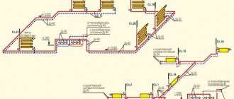
There are six such systems, but in our reality, as a rule, two are used: TN-SC and TT. Consider TN-SC, this circuit provides that the neutral wire (N) at the substation is grounded. In this case, earth (PE) and zero (N) are supplied to a private household by one wire (PEN) and then at the consumer’s electrical panel they are divided again into two.
TN-SC grounding schemes for a private house
In the case of using such a grounding scheme, the presence of automatic circuit breakers is sufficient for protection; an RCD is not necessary. But, you should know that when the PEN wire to the household breaks, a phase voltage appears on the ground bus in the house. According to the PUE rules, PEN wire protection and grounding on poles are required after 100 or 200 meters.
Due to long-term use and wear and tear, most power lines do not meet these requirements. Therefore, it is recommended to use the TT system. In this scheme, the PE wire goes to the panel from the ground loop, and not from the substation (TN-SC scheme). In this system, the protective wire is more protected, but it is necessary to use an RCD or a circuit breaker. Without them, protection is not provided; their use is mandatory.
TT grounding diagram for a private house
PUE 7, clause 1.7.59 states that if the electrical safety conditions in the TN system cannot be ensured (i.e. the main line is in such a deplorable state that it cannot ensure the reliability of the PEN conductor), then only then is it allowed to be grounded according to the scheme TT.
Main ground bus
According to clause 1.7.121 of the PUE, the following can be used as PE conductors in electrical installations with voltage up to 1 kV:
- specially provided conductors:
- cores of multi-core cables;
- insulated or non-insulated wires in a common sheath with phase wires;
- permanently laid insulated or non-insulated conductors;
- exposed conductive parts of electrical installations:
- aluminum cable sheaths;
- steel pipes for electrical wiring;
- metal shells and supporting structures of busbars and complete devices of factory production (provided that the design of the boxes and trays provides for such use, as indicated in the manufacturer’s documentation, and their location excludes the possibility of mechanical damage);
- Some third party conductive parts:
- metal building structures of buildings and structures (trusses, columns, etc.);
- reinforcement of reinforced concrete building structures, subject to the requirements of 1.7.122;
- metal structures for industrial purposes (crane rails, galleries, platforms, elevator shafts, lifts, elevators, channel frames, etc.).
P. 1.7.122. The use of exposed and third-party conductive parts as PE conductors is permitted if they meet the requirements of this chapter for conductivity and continuity of the electrical circuit.
More details
Third-party conductive parts can be used as PE conductors if they also simultaneously meet the following requirements:
- the continuity of the electrical circuit is ensured either by their design or by appropriate connections protected from mechanical, chemical and other damage;
- their dismantling is impossible unless measures are taken to maintain the continuity of the circuit and its conductivity.
The following are not allowed to be used as PE conductors:
- metal shells of insulating tubes and tubular wires, supporting cables for cable wiring, metal hoses, as well as lead sheaths of wires and cables;
- gas supply pipelines and other pipelines of flammable and explosive substances and mixtures, sewerage and central heating pipes;
- water pipes with insulating inserts.
Neutral protective conductors of circuits are not allowed to be used as neutral protective conductors of electrical equipment powered by other circuits, and also to use open conductive parts of electrical equipment as neutral protective conductors for other electrical equipment, with the exception of shells and supporting structures of busbars and complete factory-made devices that provide the possibility connecting protective conductors to them in the right place.
The use of specially designed protective conductors for other purposes is not permitted.
The main grounding bus can be made inside the input device of an electrical installation with voltage up to 1 kV or separately from it (clause 1.7.119. PUE).
Inside the input device, a PE bus should be used as the main grounding bus.
When installed separately, the main grounding bus must be located in an accessible, convenient place for maintenance near the input device.
The cross-section of a separately installed main grounding bus must be no less than the cross-section of the PE (PEN) conductor of the supply line.
The main grounding bus should, as a rule, be copper. It is allowed to use a main grounding bus made of steel. The use of aluminum tires is not permitted.
The design of the bus must provide for the possibility of individual disconnection of the conductors connected to it. Disconnection must only be possible using a tool.
Third-party conductive parts may be used to connect multiple main ground bars if they meet the electrical continuity and conductivity requirements of 1.7.122.
What is a ground loop: definition and device
A ground loop is an electrical device with low electrical resistance that allows you to quickly drain electric current into the ground. It consists of two parts connected to each other - an external and internal system. The connection of these parts is carried out in the electrical panel located at the entrance to the house.
The external system is a device that allows electric current to pass into the ground and then distribute it over an area. It usually consists of several electrodes driven (buried) into the ground and connected by welding with plates of a certain cross-section. From them, the welded tire extends into the shield, where it is connected to the inner part.
Grounding installation in a private house
What is an internal subsystem? This is the distribution of grounding wiring throughout all rooms and areas of the house to sockets and to powerful electrical installations. A common bus is formed, which is connected to the external circuit in the electrical panel.
The protective properties of grounding are very simple. If the insulation of the wires is broken, the current from the electrical network through the wires of the internal system enters the external ground loop. It flows into the ground along the electrodes of this circuit. It is known from electrical engineering that the earth has a large electrical capacity, which gives confidence in the absorption of such electrical leaks.
What is a natural grounding agent?
For safe operation of various electrical installations, grounding is required. Natural grounding is one of the common measures. It can be used as steel reinforcement, which is part of the concrete structure. In addition, other metal devices located in the ground are applicable. Plumbing communications and cables are suitable; less commonly, above-ground structures, such as metal pipes or rails, can be used for the ground electrode.
Advantages
Natural grounding agents are not made on purpose, but rather use what is at hand. In order to use metal structures as grounding conductors, they must fully comply with the requirements of the rules for electrical installations.
A natural grounding conductor can be combined with an artificial one. This scheme is used when large currents need to be diverted. The artificial ground electrode will direct the current to the natural one, through which it will go into the ground.
Natural contours are used quite often without artificial ones, on their own. Thanks to this approach, not only safe operation is ensured, but there is also a significant saving in materials spent on arranging the grounding loop.
Since the structure already exists, there is no need to install anything else, thanks to this you can significantly narrow the time frame allotted for installation and use a simple, inexpensive device.
How does the connection happen?
Regardless of what natural grounding circuit is used (reinforced concrete structure, rails, metal pipes, fittings), it is important to create a continuous electrical circuit when connecting grounding elements.
It must pass over metal surfaces. When using reinforced concrete products, more complex preparation occurs, since it is necessary to provide metal backfills. If a building is used, such bookmarks must be made on each floor. Bookmarks are elements through which electrical equipment is connected to a circuit. You can also connect any technological equipment located inside or outside the building here, and thus ground it. Many concrete structures are equipped with reinforcement lugs and have welds or bolts as connecting parts.
Such protrusions can be used to create a chain without the use of additional metal parts. In the absence of such connections, installers use flexible jumpers that can be welded to metal structures.
Attention! Jumpers should not have a cross-section smaller than 100 mm2.
What not to use
When installing working grounding, some reinforced concrete structures cannot be used, since they may not meet safety requirements. For example, if the foundation is prefabricated, it is not suitable as a natural grounding conductor, since it is unlikely that it will be possible to create a continuous circuit.
In this case, it is better to use reinforcement from blocks located close to each other. Only after such an operation will it be possible to begin the construction of natural grounding.
If for some reason it is impossible to create such a circuit, it is better to abandon the use of a natural ground electrode and create an artificial circuit.
It is forbidden to use drain pipes (sewer pipes) as a grounding conductor, since they have weak electrical contact at the joints. Reinforced concrete racks in substations can only be used if they were made using special concrete (electrical concrete).
Using the foundation
When creating a contour, you need to know how the reinforced concrete elements of the building are connected. For example, the foundation is most often connected to other elements by welding reinforcement. If the foundation is made of piles, the connection of the reinforcement of the foundation blocks with them or the piles with the grillage can be done using electric welding. It is worth paying attention to the fact that this method is not suitable for connecting metal frames and spatial columns. Their connection is made using spot welding.
It is not always possible to use a reinforced concrete foundation as a grounding conductor. Such a contour can be used only in cases where soil moisture is not lower than 3%. At lower humidity, the resistance of the foundation will be too high, which will not allow it to be used for constructing a circuit.
The foundation is suitable as a grounding loop if it is located in a slightly aggressive environment. For example, this impact includes the presence of groundwater with low hardness. Foundations that do not have waterproofing or whose surface is protected with bitumen are well suited. In this case, it is impossible to use a reinforced concrete foundation that is in direct contact with an aggressive environment. Such exposure will lead to corrosion of its elements. There are designs that include prestressing reinforcement; they are also not suitable for creating a natural ground loop.
By carefully examining the building, you can decide whether its foundation or other elements are suitable for creating grounding or not. It is worth noting that most concrete structures meet these requirements, so there is no need to create artificial grounding. Thanks to this feature of concrete structures, you will not have to spend a lot on wires. All of them will be located inside the building, which will save on their length, and this will significantly reduce the cost of materials.
Other options
There are other natural grounding agents.
To explore suitable options, you can use the PUE clause 109 of section 1.7. It states that using a steel pipeline is quite suitable. The main condition is the presence of non-flammable liquid inside the pipeline. In addition, a metal well casing can be used as a natural grounding conductor. For power lines, reinforced concrete footrests are used as grounding conductors, since they are well moistened upon contact with the ground.
Thus, using natural grounding conductors can significantly save time and money, but it is necessary to take into account a large number of factors that can affect safety. The structures must not only form a single circuit, but also provide resistance not exceeding the permissible parameter.
Types of ground loops
For the grounding system to operate effectively, it must distribute the current “draining” into the ground over several electrodes that increase the dissipation area. There are two main types of grounding systems.
Ground loop - triangle
This type of circuit uses three pins, which are welded using strips into a triangle with equal sides. The length between the electrodes is selected depending on the length of the electrode penetration to two such depths. Those. for an electrode length (depth) of 2m, the side of the triangle will be 2-4m.
Ground loop - triangle
Linear
If it is impossible to make a closed figure due to the configuration of the area, a variant of several electrodes is made, they are placed in a semicircle or in a line. The gap between the driven pins should be 1-1.5 times the immersion depth of the pins. The disadvantage of this method is the large number of electrodes.
Ground loop - linear
The proposed types are the most used in the design and installation of grounding systems. It can be made in the form of any geometric figure (rectangle, circle, etc.), but you must understand that this will require an appropriate number of grounding pins. The main advantage of such systems is that if the connection between the electrodes is broken, the functions of the grounding system are preserved.
Important!
The linear circuit operates on the principle of a garland and damage to the jumper puts a certain section of it out of service.
Isolated Neutral Systems
In all the systems described above, the neutral is connected to ground, which makes them quite reliable, but not without a number of significant drawbacks. Much more advanced and safer are systems that use an insulated neutral that is completely unconnected to ground, or grounded using special devices and devices with high resistance. For example, as in the IT system. Such connection methods are often used in medical institutions to power life-support equipment, at oil refining and energy plants, scientific laboratories with particularly sensitive instruments, and other critical facilities.
IT system
IT grounding system
The classic system, the main feature of which is the isolated neutral of the source - “I”, as well as the presence of a protective grounding circuit on the consumer side - “T”. Voltage from the source to the consumer is transmitted through the minimum possible number of wires, and all conductive parts of the consumer equipment housings must be reliably connected to the grounding electrode. There is no zero functional conductor N in the source-consumer section in the IT system architecture.
Ground loop requirements
For effective operation of grounding according to the PUE, it must comply with the rules:
- Grounding pins welded into a circuit must be located at least 1 meter and no more than 10 meters from the house. The most correct distance from the foundation is 2-4 meters.
- The rods must be driven to a depth of 2-3 meters.
- The electrodes are connected using a metal strip using welding. A bus of more than 16 square millimeters is used from the shield to the ground loop. To connect wires to grounding in the shield, it can be done using bolts.
- The grounding resistance for a voltage of 380 volts should be no higher than 4 ohms, and for a voltage of 220 volts - 8 ohms.
The external part of the grounding system is buried in the ground, so certain requirements are imposed on it. It must be below the freezing point of the soil, otherwise the electrodes will be pushed out due to swelling of the earth. The electrodes must be such that they can be driven into solid ground.
Recommended types and parameters of driven electrodes:
- corner metal thickness of at least 4 mm, any size;
- a pipe with a diameter convenient for driving, with a wall thickness of at least 3 mm;
- a rod with a diameter of at least 14 mm, a smaller one bends when immersed in the ground;
- strip for connecting electrodes, at least 3 mm thick and more than 10 mm wide.
The minimum length of the electrodes is chosen to be 1.5 meters, the pins are located at a distance of 1-2 lengths of the electrode. It should be taken into account that the electrodes (their length) should be 15-20 centimeters below the soil freezing level.
Is it possible to use fittings for grounding in an apartment?
Tell me, is it possible to use the reinforcement of a Khrushchev-type panel house as grounding? If so, would such protection be good? Second question: what can you use to ground a steel bath other than the shield? For example, to the same fittings, etc.?
Hello! If the fittings have a good connection to the ground, in principle it is possible, try measuring the voltage between the phase and your fittings. If it is close to 0, then there is land there. To understand how good the ground is, try connecting at least a 100 W incandescent lamp between the phase and the fittings. If, after connecting the lamp, the voltage at its terminals differs from that in the socket by more than 5 volts, there will be no normal protection. First of all, to prevent the bath from shocking, equalize the potentials in the room; to do this, connect all the metal elements in the room to each other, each with a separate wire to the PMC bus.
And how should a lamp burn if it is well grounded, does it dim than from a socket?
If the ground is good, then the lamp should glow brightly. But this is not entirely true. This needs to be measured with an Ohmmeter. According to the PUE, the resistance of the ground loop should be up to 4 Ohms at 380V and up to 8 Ohms at 220V, and at a facility with a 380/220V network - up to 30 Ohms. This article tells you more: https://samelectrik.ru/kak-izmerit-soprotivlenie-kontura-zazemleniya.html.
One wire to the phase and the other to the fittings shows 200-210 v, what does this mean? Could the valve be zeroed? And isn’t it dangerous to ground the fittings because they can come into contact with an iron heating riser?
How many volts between phase and zero? You've done a number of tests and all point to a bad ground. It is not clear what kind of grounding can be dangerous for the fittings and that it comes into contact with the pipeline? It is also laid in the ground.
Between phase and zero 220. Everyone says that it’s impossible to go to the fittings to the risers, that in cases where current comes through the pipes, etc. to the panel, there’s also just grounding there, where is it possible?
Why do you need grounding so much that you have been asking for permission to ground the fittings for a week now? Set the RCD at the input to 30 mA, preferably 10 (if there are no false alarms) - it will also work in a two-wire circuit when you touch the current-carrying part. The fact that there is 220 is without load, many also have a heating battery, if you connect a light bulb, it won’t even try to burn, and the multimeter shows the rated voltage.
I checked that when connected to the socket the LED lights up normally, but when connected to the fittings it lights up dimly by about half, will this be a normal grounding?
We are developing a scheme
In order to organize a grounding device for a private house, it is necessary to work out a grounding circuit diagram. The most popular and most frequently used is the triangle diagram.
As a rule, 3 electrodes stand at its vertices; you can add additional ones, which are driven in a straight line between the vertices.
If it is impossible to make such a contour, the electrodes can be installed in a line, rectangle, semicircle or wave. But it should be noted that the triangular ground loop scheme is much more efficient.
Rules of service
Care and maintenance of the electrode does not bring much trouble, as it is not complicated. Maintenance consists of the following: once every few years it is necessary to open the electrode cover and also determine the level of the salt mixture in the structure. If the mixture is completely converted into an electrolyte, the required amount of salt should be added to the electrolytic ground.
This is the whole essence of service. The electrode can be charged for many years (up to 15 years of service). Therefore, it is recommended to carry out the first inspection after this period of time.
Finally, we recommend watching a video that clearly demonstrates how to make electrolytic grounding with your own hands:
So we looked at the device, purpose and rules for installing electrolytic grounding. We hope that the instructions provided were useful and interesting for you!
Ground loop materials
The electrodes for the grounding system are made from a durable metal profile or rod. If they are thick enough, their electrical resistance must satisfy the requirements. They can be driven into the ground relatively easily by hammering them. Materials used for the manufacture of the ground loop:
- Kernel. A rod with a diameter of more than 14 mm is taken. Reinforcement, as a rule, is not used for these purposes, because When hardening reinforcement, its resistivity increases.
- Pipe. Diameter more than 40 mm, wall thickness not less than 4 mm. It is recommended to make holes at the bottom of the pipe. In arid climates and weather, salt water can be poured into the pipe, this increases the electrical conductivity of the soil.
- Corner. Size 50x50, thickness at least 4 mm. The bottom of the corner is made sharp, which facilitates the process of driving it into the ground.
Reinforcement as a universal material
Steel reinforcement, which is solid metal rods, is widely used to strengthen and increase the load-bearing capacity of the main structure in buildings and production. Reinforcement is used mainly in those places of a building structure that are subject to tensile effects (bending, tension, compression). This type of rolled metal is the most important component of reinforced concrete. In accordance with GOST, steel reinforcement is made from high-strength low-alloy steel or the reinforcing steel is subjected to heat treatment and strengthening of its physical properties. Steel reinforcement consists of bars or rods of various sizes from which the desired structures, such as a mesh or frame, are made. Based on the nature of the profile, it is divided into smooth and corrugated. According to manufacturing technology, there are 2 types of reinforcement: hot-rolled rod and cold-drawn wire.
What to make metal connection from
Metal connection, i.e. The connection of electrodes driven into the ground is carried out using the following materials:
- Copper wire or bus, cross-sectional area - 10 square meters. mm and more.
- Steel tire, cross-section - 48 sq. mm.
- Aluminum wire or strip, cross-sectional area more than 16 square meters. mm.
For such purposes, a steel strip of 25-30x5 mm is preferable. The connection of such a strip to the electrodes is made using electric welding, which ensures a reliable connection. When using aluminum or copper conductors, the connection is made using a bolted connection.
Location of grounding device pins
Grounding calculator
In order to simplify the calculations, we suggest you use a simple and accurate grounding calculator.
Our online grounding calculator takes into account all correction factors and works based on the given formulas. In order to perform a reliable calculation, you need to fill out the program fields correctly.
- Soil . Specify the top and bottom soil layers, as well as the depth.
- Climate coefficient. Amendment in calculations based on climate zone: Zone I - from -20 to -15°C (January); from +16 to +18°С (July);
- Zone II - from -14 to -10°C (January); from +18 to +22°С (July);
- Zone III - from -10 to 0°C (January); from +22 to +24°С (July);
- Zone IV - from 0 to +5°C (January); from +24 to +26°С (July);
Self-installation of grounding
A location must be selected for the ground loop. It should be located where people and your pets will least likely enter. There should be a distance of more than 1 meter from the foundation. Marks are made on the site where the pins will be located. They are arranged in the shape of an equilateral triangle.
Excavation. After applying the markings in a straight line between the pins, a trench half a meter deep is dug. The same trench for laying the busbar is dug from the ground loop to the input electrical panel.
Next, adhering to the chosen pattern, we drive in the rods to the required length. They are connected by a strip of metal by welding. Next, the busbar welded to the ground loop is laid in the trench to the electrical panel.
Entering the house. The bus connected to the house is inserted into the electrical panel. A hole is drilled in it and connected with a bolt and nut to a specific cable core. With the TN-CS scheme, the busbar inserted into the shield is connected to the busbar - the splitter.
Application Feature
As the freezing temperature of the soil decreases, a talik zone forms near the device. It can pose a danger to the foundations of buildings, objects and road surfaces that are nearby. The talik zone has the shape of an oval and its size on the soil surface is 3x6 meters.
During design work, it is necessary to take this fact into account and install electrolytic grounding at a certain distance from objects and buildings to which it can cause damage and harm.
Examination
After completing all installation and connection operations of the ground loop, it is necessary to check it by measuring its electrical resistance. The parameters of this value should not exceed the limits specified in the regulatory documents.
You can use a simple test method at home. A light bulb from 100 to 150 W is connected between phase and ground.
Checking grounding performance using a lamp
Based on the glow of the lamp, conclusions are drawn:
- if the lamp does not light up, the grounding is done incorrectly;
- the lamp burning with a dim, dim light indicates a poor-quality connection of the ground loop elements or connections during connection;
- A bright lamp indicates good grounding performance.
During such a check, if there is an RCD in the circuit, it may operate, which indicates the operating condition of the circuit.
Check with a multimeter.
Checking grounding with a multimeter
It is carried out according to the following method:
- it is necessary to apply voltage by turning on the input circuit breaker;
- On the multimeter, select the voltage measurement mode;
- We connect the ends of the multimeter between the phase and neutral wires. The device should show a value around 220 volts;
- We make a similar measurement between the phase and the ground wire. The voltage may be slightly different from the previous measurement, but its very presence indicates the presence of ground;
- if there is no voltage, then there is no grounding, or it is not working.
The inspection can be entrusted to professionals. This check is shown in the video:
Checking the ground loop by professionals
Standards of PUE grounding
Grounding PUE standards are a set of regulatory legal acts. These rules include recommendations on how to carry out electrical wiring correctly, a description of various electrical installations and the principle of their operation, as well as the requirements for electrical systems and their components.
Grounding installation work must be carried out in accordance with the electrical installation regulations. The criteria defined in the PUE will allow all connections to be made without errors, maintaining all standards. This guarantees reliable operation of the protective system in the house and will avoid the negative consequences of natural and man-made impacts.
If you unquestioningly follow all the rules described in the PUE, this will lead to large financial costs, so electricians and engineers follow only very important recommendations in their activities.
In accordance with the rules of the PUE, a repeated protective circuit must certainly be located at the exit areas from the premises. It is recommended to install natural grounding electrodes at this location. These include reinforced concrete devices, large metal parts, which for the most part are directly connected to the ground.
The PUE also specifies items that cannot be used as grounding conductors: energized metal objects, sewer and heating pipes, as well as pipelines with flammable substances.
When installing grounding, it is necessary to carefully carry out calculations, taking into account all the factors affecting the quality of the device being created, and it is necessary to follow the PUE.
Ready-made kits
Making grounding yourself can significantly reduce costs. But there are ready-made kits that can increase the reliability of the circuit.
Ready-made kit for grounding installation
The following models are available on the market:
Elmast - the system is manufactured in Russia. Cost - 8000 rubles.
ZandZ - stainless steel electrodes. The depth of immersion in the ground is up to 10 meters. The kit will cost 23,500 (electrodes 5 meters long).
Galmar - average cost - 41,000 rubles (electrodes up to 30 m long).
There are several models on the market for Russian consumers. This gives you a lot of options to choose from. The cost ranges from 6,000 to 28,000 rubles.
Installation of a ground loop in a private house
Principle of operation
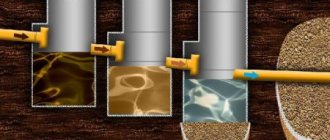
The device operates on the basis of chemical reactions that increase the electrical conductivity of the soil. Electrolytic grounding works according to the following mechanism:
- The mixture, which is poured into a full electrode, absorbs water from the environment through special holes in the device.
- A reaction of water with salt occurs and as a result an electrolyte is formed, which seeps into the soil. Thanks to this mixture, the soil becomes more electrically conductive and less prone to freezing.
This reaction occurs regardless of the ambient and soil temperature.
Types of material (profiles)
According to the requirements of the PUE, which contain instructions on what the resistance of current flow in the ground should be, in most cases this indicator is set at a level of no more than 4 ohms. To obtain this value, you usually have to make a lot of effort to adhere to the same technology requirements.
First of all, this concerns the materials used in assembling the grounding loop, selected based on the following conditions:
- When choosing pins, preference should be given to ferrous metal blanks;
- The most commonly used rod is a standard size of 16-20 mm or a corner with parameters 50x50x5 mm and a metal thickness of about 5 mm;
- It is not allowed to use reinforcement as circuit elements, since it has a hardened surface that affects the normal flow of current;
- For these purposes, it is pure rod that is suitable, and not its reinforcement substitute.
Note! For areas with dry summers, thick-walled metal pipes are best suited, the lower end of which is flattened into a cone, and then several holes are drilled in this part of the pipe. According to the provisions of the PUE, before placing them in the ground, holes of the required length are first drilled, since driving them manually is quite problematic
In the case of a particularly dry summer and a sharp deterioration in the parameters of the ground electrode, a concentrated saline solution is poured into the hollow parts of the pipes, which makes it possible to obtain the resistance that should be in accordance with the requirements of the PUE. The length of pipe blanks is selected within 2.5-3 meters, which is quite enough for most Russian regions
According to the provisions of the PUE, before placing them in the ground, holes of the required length are first drilled, since driving them in manually is quite problematic. In the case of a particularly dry summer and a sharp deterioration in the parameters of the ground electrode, a concentrated saline solution is poured into the hollow parts of the pipes, which makes it possible to obtain the resistance that should be in accordance with the requirements of the PUE. The length of pipe blanks is selected within 2.5-3 meters, which is quite enough for most Russian regions.
This type of profile blanks has special requirements regarding the order of their placement in the soil and consists of the following:
- Firstly, the pipe elements of the protective circuit must be placed at a depth exceeding the soil freezing level by at least 80-100 cm;
- Secondly, in particularly dry areas, approximately a third of the length of the ground electrode should reach wet soil layers;
- Thirdly, when fulfilling the second condition, one should focus on the peculiarities of the location of the so-called “groundwater” in a given region. If they are located at a significant depth, according to the rule formulated in the provisions of the PUE, it will be necessary to prepare longer pipe sections.
The type and profile of the pin blanks used in the construction of the grounding switch can be found in the figure below.
In practice, in most regions of Russia, a steel corner and a strip of the same metal are usually used. In order to obtain more accurate parameters of the grounding elements used, geological survey data will be required. If this information is available, it will be possible to involve specialists in calculating the parameters of the ground electrode.