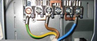
Connecting a private home to the electrical network involves installing a metering panel in which an electricity meter and protective devices will be mounted, an input from the electrical network and an outgoing cable that powers the home wiring will be connected. Often, one of the requirements of the supplying organization that connects to electrical networks is the installation of a metering panel on a support (pole). In this article we will provide readers of the Sam Electric website with basic recommendations on this issue.
Electricity metering panel for a private house: diagram, assembly, installation
Introduction
The issue of connecting a private home is one of the most discussed on the Internet. One of the reasons for such popularity is the division of connection work between the home owner and the operating organization. So the owners are looking for how to do their part of the work correctly. Fortunately, there is useful and practical information and here you can find excellent information assistants. In this article we will talk about an electricity metering panel for a private home.
Owner connection activities
By connecting a house to power lines, the owner of the house receives technical conditions for connection. It has a section that lists what the owner must do to connect.
I will give an excerpt from such a technical specification. The owner is obliged to install a metering unit with protection devices for power receiving devices, 25 Ampere circuit breakers that control the amount of power and an electricity consumption meter with accuracy class 2.0.
Let us clarify what is meant in this specification and how to implement this requirement.
Outdoor electricity metering panel for a private house
Whatever disputes arise regarding the location of the metering board installation, the preferred location for energy companies remains an outdoor location with free access for supervisors.
This means that we will need a power metering panel for street installation on a pole (support) with a housing protection level of at least IP54.
You can assemble this shield yourself, or purchase a ready-made version from the manufacturer.
Shield diagram
You need to assemble the electricity metering panel of a private house according to the diagram. Here is one version of it, which can be called generalized and recommended.
On the circuit diagram of the shield we see:
- A branch from a 0.4 kV overhead power line support is made with a self-supporting insulated SIP wire 4×16, which means four cores in total insulation with a cross-section of 16 sq. mm.
- On the input side, the shield is protected by a common three-pole 50 Ampere circuit breaker.
- The electricity meter has an accuracy class of 2, and is designed to operate in a network from 5 to 60 Amperes.
- Electrical energy is distributed into several groups: two three-phase (380 V) at a power of 32 Ampere and 20 Ampere, and one single-phase 220 V at 10 Ampere.
- The switchboard itself must be provided with a grounding system made in accordance with the standards. The panel body, as well as the busbar for connecting the PE protective wires, must be connected to the grounding loop made for the installation pole.
Assembling the metering board
It’s not difficult to assemble such a shield yourself.
It is important to follow a few simple rules: . Input and output wires should not touch the metal body of the switchboard and should not press on each other
For this purpose, all passages through the housing are protected with plastic sleeves and are sufficient for free passage of the cable.
The installation wires inside the switchboard should not intersect, especially at angles other than 90˚.
All wire connections to the PE bus must be visually visible, and the tightening screws of circuit breakers and terminal blocks must be accessible for tightening.
To avoid temporary weakening of the connections of wires and busbars, they must be made not only through a washer, but also reinforced with a locking washer (DIN 127).
- The input and output wires should not touch the metal body of the switchboard and should not press on each other. For this purpose, all passages through the housing are protected with plastic sleeves and are sufficient for free passage of the cable.
- The installation wires inside the switchboard should not intersect, especially at angles other than 90˚.
- All wire connections to the PE bus must be visually visible, and the tightening screws of circuit breakers and terminal blocks must be accessible for tightening.
- To avoid temporary weakening of the connections of wires and busbars, they must be made not only through a washer, but also reinforced with a locking washer (DIN 127).
Installation of metering board
The metering board is installed on the street at a height of 1200-1600 mm, on a pole (support) indicated as the input one. The descent of wires to the switchboard and the lifting of wires from the shield are carried out in pipes or boxes or openly on clamps. The descent of wires from the switchboard to the house in a trench is carried out only in a pipe with the pipe turning into the trench.
Grounding the metering board
The metering board is grounded locally. A wire of at least 10 mm or a metal strip is laid from the shield down the pole with secure fastening to the pole with clamps.
For the grounding itself, the reinforcement of a concrete support or a separate pin driven into the ground to a depth of 1.8-2.0 meters is used until the standard grounding resistance is reached, 4 Ohms for 380 V and 8 Ohms for 220 V (PUE 7, 1.7.101.)
E
Information for gardeners
An open request for proposals was announced in electronic form No. 126e dated 08.14.18 for the supply of a complete two-transformer substation 2KTP 250/10/0.4 kV, size 6650x7200 with 2 (Two) power transformers TMG 250/10/0.4 kV Y/Y- 0, according to the questionnaires and technical specifications (Appendices No. 2, No. 3 and No. 4).
An open request for prices in electronic form No. 125e dated 08.08.18 has been announced. for the purchase of cable ASBL 3x150 10 kV.
An open request for quotations No. 122 dated 08/06/18 was announced for the implementation of work on laying a case for an electrical cable using the HDD method at the facility: “CL-1 kV from RU-0.4 kV TP-31 for power supply to the power receiving device of a non-residential building with cadastral number 58:29 :4005011:51, Penza, st. Belinskogo, 8" (project code 151-07-18-ES)
An open request for proposals was announced in electronic form No. 123e dated 08/07/18 for the supply of ASBL cable 3x240 mn 10 kV (reconstruction of 2KL-10 kV substation 110/10 kV "Novokazanskaya" - RP-19)
An open request for prices has been announced in electronic form No. 124e dated 08/06/17 for the supply of: No. Name Quantity Minimum construction length Unit. change Product requirements1 Cable AVBShv 4x240 1kV (technical connection Penza, Ladozhskaya St., 1B) 410 205 m GOST 31996-2012
2 Cable AVBShv 4x240 1kV (technical connection Penza, Belinsky St., 460 230 m GOST 31565-2012
Organizational matters
First of all, it should be taken into account that the electric grid company makes a connection directly to the power grid only if all requirements for installing a metering panel and completing all necessary documents are met.
Therefore, the first stage is drawing up a project and approving it in the power grid organization. As a rule, an organization has standard designs for connecting to electrical networks and a list of requirements regarding the selection of the rating of protective devices, the type of electric meter, the cross-section of the input wire (cable), the type and design of the housing of the metering and distribution panel, as well as requirements for mounting the panel itself on a support or in the other place. It is possible that, at the request of the supplying organization, it will be necessary to connect the meter to an automated commercial electricity metering system (ASKUE).
Situations often arise when, after purchasing an input cable, installing a switchboard, metering device and the necessary protective devices without prior approval, the energy supply organization refuses to connect to the power grid and you have to correct installation errors or re-purchase a new electric meter, protective devices and other elements.
Therefore, if you already have a ready-made project, then before purchasing the necessary structural elements and proceeding with the installation of the electrical panel, you should agree on the project with the supplying organization.
Nuances of grounding a private house
There are several options for arranging a ground loop. The specific method is selected taking into account the type of soil on the site and the characteristics of the house. Regardless of the chosen method, it is recommended to make grounding electrodes from pipes, one of the ends of which is pre-flattened to a point.
On the lower section of each pipe (the length of the section should be about 50 cm), 10-15 holes with a diameter of about 5-7 mm are made randomly.
In hot weather, it is recommended to pour a saline solution inside the grounding pipes. To prepare it, just dissolve half a pack of salt in a bucket of clean water. This solution will help maintain resistance at a normal level.
The grounding bars also remain the same regardless of the method chosen. You should refrain from using galvanized steel to create metal bonds - the material will very quickly lose its performance properties.
First step.
Calculate the contour. To do this, you need to find out the soil resistance value in your area. Find out this information in the relevant reference literature or local services. The same service can give you recommended circuit parameters. This will save you from unnecessary hassle, because the calculation formulas are quite complex and voluminous.
Second step.
Choose a suitable location for the circuit. Install the circuit in some place that is rarely visited, the minimum distance from the foundation of the building is 100 cm.
Third step.
Prepare the electrodes. They can be made from steel angles. The minimum width of the product is 5 cm, the optimal length is 250-300 cm.
Fourth step.
Dig a square or triangular hole about 100 cm deep. The electrodes will be placed in the corners of the pit. Therefore, select the depth and width of the pit so that the distance between the installed electrodes is equal to the length of these products.
Fifth step.
Drive the prepared electrodes into the corners of the dug hole. A sledgehammer will help you with this.
Sixth step.
Weld a strip of metal to the electrode pins. The welded connection must be reliable and of high quality. Be sure to treat the welding areas with an anti-corrosion compound, for example, bitumen mastic.
Seventh step
. Pull the metal strip to the input shield. Next, you will need to connect a ground bus to the strip.
If it is not possible to use a full bus, connect a high-quality copper wire to the metal strip. The cross-section of this wire must be at least 10 mm2. Use a bolt and nut to secure the wire. Treat the connection point between the metal strip and the copper wire with an anti-corrosion agent.
Eighth step.
Fill the hole. Firmly compact the backfilled soil.
Design and purpose of grounding devices
Such structures are divided into working and protective devices.
- The worker is used to organize the safe operation of industrial units. Also common in private households.
- A protective grounding system is required for electrical networks in the residential sector.
Installation of a grounding device (GD) is required in accordance with the Rules for the Construction of Electrical Installations and the Rules for the Operation of Consumer Electrical Installations.
People touching live parts exposed as a result of improper operation of electrical equipment, design defects, deterioration of insulation and other reasons is common. Poor-quality design of the charger and its installation can lead to serious consequences for people: electric shock, burns, disruption of the heart and other human organs, electric shock often leads to amputation of limbs, disability and even death.
The grounding system consists of external and internal parts, which are joined in the electrical panel. An external grounding device consists of a complex of metal electrodes and conductors that drain emergency current from electrical equipment into the ground in places that are safe for people. The electrodes are called ground electrodes. Electrical conductors are grounding conductors; they are pins 1.5 m long and 1 mm in diameter.
They are manufactured industrially from copper or copper-plated steel. Their main advantage is increased current conductivity. They are driven into the ground with hammers or sledgehammers to a depth of 50 cm; contact with the ground must be as strong as possible, otherwise the structure’s ability to drain current will deteriorate.
The simple design is made from a single electrode. Used in lightning rods or to protect remote objects and equipment. In individual farms, preference is given to multi-electrode devices. They are placed in one row and are called linear memory profiles. The standard chain length is 6 meters. They are connected to each other using brass couplings; the fastening is threaded; welding is not recommended. Grounding conductors are installed through terminals. Twisting and soldering of cores are excluded.
Read also: Air humidifier: how to choose the best one for your apartment
A device such as a ground loop (closed version) is still common. It is constructed at a distance no closer than 1 meter and no further than 10 meters from the house. Placed in a trench in the form of an equilateral triangle. Side length 3 m, depth – 50 cm, width – 40 cm. Grounding conductors are driven into the corners. The same operation is performed with other vertical electrodes (no more than five units). Grounding conductors in the lower supporting part are welded to horizontal products.
They are made of copper, copper or zinc coated steel angle (5 mm flange, 40 mm strip). A standard stainless steel angle of any profile is often used. The products are not painted, as in this case the electrical properties will deteriorate due to weakened contact with the ground.
The design of the circuit is simple; you can do it yourself. But the work is simplified when using ready-made grounding devices on the market, complete with grounding wires. Financial losses will be recouped through the use of high-quality materials that are resistant to corrosion and have a long service life.
Installation work
Step 1 - Choose a location
First you need to decide where to make the grounding loop
The importance of this stage is very high, because The safety of using the system depends on the choice of grounding location in a summer cottage
If a breakdown of the electrical wiring occurs, as a result of which the protection is triggered, then there should be no one in the place where the pins are located. The presence of a person or animal at the site where electricity is discharged into the soil can cause death. That is why the location of the electrodes is chosen taking into account the fact that no one will be there. It is best to place the outlet along the fence behind the house, at a distance of no more than 1 meter from the foundation of the building. Additionally, it is recommended to make a low fence or border to fence off the unsafe area.
If you do not want to spoil the landscape design of the area, we recommend organizing a grounding system for your residential building under boulders or some kind of voluminous garden sculpture. In this case, no one will be able to be in the danger zone and nothing will harm the beauty of the garden area!
Step 2 - Excavation
For example, let's look at how to properly ground a private house with a triangle according to the scheme we discussed above. At this stage, you need to dig a triangle with sides of 1.2 meters with a shovel (the most optimal distance between the corners). The depth of the trench should be from 50 to 70 cm. The same trench should be dug to the porch of the house.
Is it possible to separate the PEN conductor after the energy meter?
Is it possible to separate the PEN conductor after the energy meter?
Post by Serex » 02 Aug 2021, 01:27
I’m trying to justify my point of view regarding the connection to the overhead lines (OHL) of my building. Now connected: a branch from the overhead line 4 wires - 3 phases and PEN are inserted into the energy metering panel. The panel has a 3p machine and a counter. There are no N and PE tires. The shield is not grounded, although it is metal. After the meter, 4 wires go to my building.
The problem is that the electrician who connected all this is suggesting that I make a TT grounding system, despite the new poles and insulated SIP cables on the poles as an overhead line and a new building. I would like a TN system, which is considered more reliable.
What and how to ground
First group. On the back wall of these devices you can find a special terminal, usually a screw terminal, for separate (direct) grounding of the housing.
Most likely, there will be no mention of it in the instructions for electrical appliances, since its presence automatically transfers the device from the class of household to industrial devices.
But despite this, many manufacturers place it on:
- Washing machine (sometimes dishwasher). It definitely needs to be grounded through a Euro socket, since it has a large electrical capacity and is most often installed in a damp room.
- Microwave. The working source of wave radiation in it is a powerful magnetron, and even with minor wiring defects or poor contact in the socket, it is capable of breaking through.
It is not necessary to trust the installation and connection of a power outlet for an electric stove to specialists; the main thing is to have detailed instructions on hand that will help you figure out what and how to do.
You can learn more about installing and connecting an electric meter by reading this article. After this, you can connect an electric meter with one or three headlights yourself.
Second group. For safety reasons, it is advisable to ground them.
- Induction hob (electric hob) and electric oven. The internal wiring in them operates at high temperatures, and the power is quite high.
- Desktop computer. If you ground the computer's power supply directly (at any screw on the rear panel), this will eliminate not only periodically occurring floating potentials, but also some “glitches” of the computer. Even the Internet speed may increase.
- Hydromassage boxes (especially with steam generators). Manufacturers from China did not bother to worry about safety, so it must be grounded directly from any metal fastening under the pallet.
Introductory board on a pole
I agreed to double the capacity. As a result, the agreement with Energosbyt will include an 8 kW input per phase. The input to the house will be laid with a VVGng 3x16 cable in a technical HDPE pipe. Grounding using the TN-CS system.
I was prohibited from altering the entrance cabinet myself, citing the fact that the switchboard would not be accepted and this alteration should be carried out by an electrician...
For the switchboard we purchased: - a 40A input circuit breaker from Legran - a 300mA selective RCD from ABB - a 40A home circuit breaker from ABB - a 25A circuit breaker from ABB for an additional panel on the site (for welding, etc.) - a distribution block RBP-95 for organizing PEN branching - M10/10 terminal for the output of the ground wire for the cable, which will subsequently be connected to the 25A machine - installation was carried out with PV3 wire 10 squares in double insulation.
The counter remains the same - Mercury 200.02
The cable for connecting to the pole was laid in advance and was waiting in the wings. A trench was dug to the pole into which the cable was laid. On top, for protection, I laid special slabs so that in the future I would not break it with a crowbar or shovel. I talked about these slabs here.
I put a metal pipe on the HDPE pipe, which I had previously painted gray.
In the metal shield, using a “cricket” (a device for cutting metal with a drill), I widened the holes for the seals. Using a stepped drill, an additional hole was made for entering the SIP cable. They did not put an oil seal under it - the shield is so not airtight that there is no special meaning in it. The hole and corrugation were processed so that the cable was not damaged by the edges.
The diagram of the shield on the pillar turned out like this:
Since three modules were used from ABB, I used a regular bus to connect them. This made the installation compact and there was no need to fuss with the cable to connect them. The only thing is that when using the bus, the cable entry into the RCD had to be done from below, and not from above. But this is not critical - you can do it this way.
The RBP-95 block was used in order not to tear the PEN cable, but simply pass it through, cutting off the insulation. The ground connection was made with a crimped conductor of PV3 wire 16 squares. It was crimped with a manual hydraulic press from the KVT PGR-70. It was fastened with M8 bolts directly to the RBP distribution block -95 — the photo shows the mount.
Since the old shield was used - the one that had already been on the pole, for internal peace and from the “pioneers” it was decided to make an internal opening/closing door from duralumin.
I had a scrap of duralumin, as well as corners, which I attached with rivets to the inner side surfaces of the cabinet, 2.5 cm from the edge.
It turned out that the door is located slightly ABOVE the machines, but this does not interfere with their control. It turned out that the 3x16 input cable is so “oaky” that it was not possible to press it additionally so that the homemade plastron door could be lowered closer to the machine.
Well, not scary...
Riveted corners measuring 20x40mm. On the left side of the corner, before installing it in the cabinet, I riveted another corner - a little smaller in size so that the lock would close normally - so that the tongue from the lock would fit snugly.
Here in the photo you can see how the second corner is attached.
On the right side, I riveted a couple of hinges to the corner and already attached a duralumin plastron door to them:
Before installing the corners, I moved the meter to the right - closer to the input machine, so that the corner on the left did not overlap the meter display. From the RBP-95 block, I brought out a 10-square wire to the M10/10 terminal to connect the ground of the cable that will be connected to the B25A machine.
Finally, I pasted a sticker:
To re-ground, I drove a 63x63 by 2m corner next to the pole and connected it to the existing one. History is silent about the depth to which the old corner was hammered. Accordingly, the fastenings were moved to the new corner.
All that remains is to make a more or less normal fastening of the pipe to the pole and ground the panel door.
The cable will enter the house into this distribution panel:
Subsequently, additional grounding of the cabinet doors was done - both main and additional.
www.snthouse.ru
SEARCH
- COUNTER PER POST
- INTRODUCTION SHIELD
- ASU 15 KW 380V
- TECHNOLOGICAL CONNECTION
- METER ON PIPE STAND
- PIPE STAND
- INTRODUCTION BOARD WITHOUT RCD
- CONNECTION AND INSTALLATION OF ASU 15 KW 380V ON A POLUMLE
- INPUT SHIELD 220 V
- SHIELDS ON A PILLAR
- ELECTRIC METER ON A POLUMLE
- ELECTRICAL CONNECTION
- COUNTERS IN SNT
- INSTALLATION OF METERS IN SNT
- SEALING TIRE ZERO
- MERCURY 233
- COUNTER MATRIX
- ADDITIONAL EQUIPMENT FOR ASP SHIELD 15 KW 380 V
- PASSPORT OF THE SHIELD OF ASU 15 KW 380V
- EQUIPMENT CATALOG
- CUSTOMER REVIEWS.
- POWER LIMITER
- ACCOUNTING SHIELD
- SPD
- POLE MOUNT
- COMPLIANCE WITH TECHNICAL CONDITIONS FROM MOESK
- ACCOUNTING AND DISTRIBUTION BOARD
- ELECTRICAL
- QUESTIONS AND ANSWERS.
- SHIELD FUNCTIONS
- CABINETS. BOXES.
- DISTRIBUTION BOARDS
- ELECTRICAL SHIELD
- INDIVIDUAL ORDER
- SERVICES
- ELECTRICAL BOARDS
- ELECTRICAL BOARD
- APARTMENT BOARD
- ELECTRICAL BOARDS.ELECTRICAL SHIELD
- INPUT SHIELD INPUT SHIELD
- APARTMENT SHIELD
- POWER SHIELD
- SHIELDS IN THE APARTMENT
- PHOTO OF SHIELDS
- ELECTRICAL BOARD FOR A WOODEN HOUSE AND Cottage
- SHIELD ON DIFAVTOMATS
- ELECTRICAL BOARDS FOR HOME AND Cottage
- STOREY SHIELD
- LIGHTING BOARDS OSCH
- AUTOMATION SHIELD
- DISTRIBUTION CABINET
- CONTROL CABINETS
- VRU CABINETS
- INPUT DISTRIBUTION DEVICE
- INPUT DEVICE
- ASSEMBLY OF VRU
- VRU PASSPORT
- SHIELDS
- SHIELD
- DISTRIBUTION BOARD
- DISTRIBUTION BOARD FOR HOUSE CONSTRUCTION.
- INSTALLING THE SHIELD
- INSTALLATION AND CONNECTION OF THE SHIELD.
- ELECTRIC INSTALLATION WORK
- DISCONNECTING SHIELDS
- ASSEMBLY OF ELECTRICAL BOARDS AND ELECTRICAL EQUIPMENT
- ELECTRICAL SHIELD. SHIELD ROOM.
- CONVERTED SHIELD IN THE APARTMENT
- SHIELD BULKHIP
- ELECTRICAL IN THE APARTMENT
- ELECTRICAL IN WOODEN HOUSES
- ELECTRICAL SHIELD ASSEMBLY TECHNOLOGIES
- AGREEMENT
- QUALITY OF WORK PERFORMED.
- MEDICAL EQUIPMENT. MEDICAL SHIELDS
- ELECTRIC CABINET
- ELECTRICAL WIRING INSTALLATION
- WIRING
- REPLACEMENT OF ELECTRICAL WIRING
- CONNECTION TO ELECTRICAL NETWORKS
- ELECTRICITY CONNECTION
- CONNECTION TO THREE-PHASE NETWORK
- CONNECTING TO NETWORKS
- CONDUCT ELECTRICITY
- POWER CONNECTION.
- TECHNOLOGICAL CONNECTION TO ELECTRIC NETWORKS
- TECHNOLOGICAL CONNECTION TO NETWORKS
- MERCURY 230
- MERCURY 234
- MERCURY 200
- MERCURY 231
- MERCURY 201
- PIPE STAND FOR ELECTRICITY INPUT
- INSTALLING AN ELECTRICITY METER
- REMOVAL OF METERS ON A POLUMLE
Grounding circuit without welding in country conditions
Not all owners of summer cottages have the opportunity to perform welding work. At the same time, there are requirements to connect the elements of the ground loop only by welding. You can do it differently: prepare grounding pins where it is possible to weld a galvanized bolt to each of them.
Grounding diagram at the dacha
On a summer cottage, to install a grounding loop, you first need to dig a 0.5 m deep ditch next to the house. Now all that remains is to hammer the pins into the bottom of the trench and connect one whole grounding wire with a cross-section of at least 10 mm2 to all of them. The joints should be treated with anticorrosive and wrapped with several layers of electrical tape.
The resistance of the finished circuit, of course, needs to be checked.
Another way to ensure grounding without welding is to purchase a special ready-made set of copper-plated rods. Such a kit costs a lot, which will not suit everyone.
Examples of grounding connections without welding
In this case, it is quite possible to purchase galvanized pipes of small diameter, flatten and make one end sharp. Such rods are driven into the ground according to the above plan. You can connect to them using galvanized clamps with a clamping bolt, which are also commercially available. The joints should be treated with anticorrosive and wrapped with several layers of electrical tape.
Thus, we examined the features of arranging grounding in a country house with our own hands. With some effort, it is not at all difficult to provide protection against electric shock to a person. We have put together an informative video for you about how others did it.
Electrical panel grounding
Very often the question arises about how to ground an electrical panel. In this case, first of all, it is also necessary to be guided by the requirements of the supplying organization.
If there are no requirements, it is necessary to ground the panel taking into account the grounding system of the electrical network. Most consumer networks have a TN-C grounding system, which involves combining the neutral and protective conductors into a PEN conductor along the entire length of the line. The point of separation of this conductor into protective grounding and neutral conductors is carried out in the shield up to the electric meter, and after separation the grounding system is called TN-CS. According to the rules, the PEN conductor has several repeated groundings on supports along the entire length of the line and at the end, in the metering panel itself on a support (pole), it is also grounded.
The PEN conductor is connected to the metal body of the electrical panel, and the panel, in turn, is connected to a pre-installed grounding conductor (grounding circuit) using a grounding conductor. The cross-section of the grounding wire must be no less than the cross-section of the input power cable.
But it is important to consider that grounding home wiring and the PEN conductor in particular can be not only useless, but also dangerous. If the supply line is in unsatisfactory technical condition, and the repeated grounding of the PEN conductor on the supports (poles) of the line does not meet the requirements, then in the event of a rupture of the PEN conductor, a dangerous potential may appear on the body of the grounded switchboard. In this case, an equalizing current will flow through the grounding conductor and the grounding loop, which can lead to damage to the input cable.
Consequently, if the grounding of the supply line does not meet the requirements for the declared grounding system of the electrical network, then it is better to use the combined PEN conductor of the input cable exclusively as the neutral input wire. In this case, you can implement a CT grounding system with your own hands, that is, install an individual grounding circuit of the wiring and ground the metal body of the electrical panel to it.
Finally, we recommend watching a video that clearly shows the installed grounded shield on a pole:
That's all the recommendations we wanted to provide you with. We hope that now you know how to install a metering panel on a support in accordance with the PUE and what requirements apply to this type of work. We hope the information provided was useful and interesting for you!
Subscribe to the newsletter
The standard home grounding system is quite simple: a ground loop is installed in the yard or basement, from which a conductor is drawn, connected to the home metering panel, or more precisely to the ground bus (PE) on it. From this bus, ground wires extend to outlets, bathroom hardware, and other objects that need to be grounded.
In this case, the grounding of the metering panel (board) is often overlooked. The electricity metering panel is a box that houses the meter, automation, RCD, zero bus, ground bus, etc. At the same time, the direct internal placement of the PE bus does not yet guarantee full grounding of the metering panel (board), since this must be done correctly.
To ensure that the grounding of the metering panel (board) is stable and complete, the PE bus can be mounted directly on its body, which has previously been cleaned of paint, varnish, dust and dirt at the contact point. In this case, more reliable grounding will be obtained if a separate grounding conductor is connected from the PE bus to the switchboard body.
Figure 1. Example of proper grounding of an electricity metering panel
It is worth noting that the electricity metering panel contains all the equipment for supplying and metering electricity, as well as means of protecting against network faults, so the safety of the electrical panel must be taken with full responsibility. Reliable grounding is one of the factors of such safety.
To install a subscriber branch to a private home, it may be necessary to install an electrical panel on a pole. In this case, the main switchboard, where the input machine and metering meter are located, is fixed directly to the power line support.
Electrical panel design
Electrical panels used to supply power to country houses and cottages have the following components:
· electricity meter;
· zero bus;
· RCD;
· grounding bus;
· several automatic machines (introductory, for high-current and low-current sockets, for lighting devices).
The complete set of the switchboard, as well as its installation, should be entrusted to an experienced electrician. The presence of errors in this case is unacceptable.
Shield on a pole - installation, assembly, assembly
For private houses, models with a voltage of 220V are selected, and mounting on a vertical surface is required. Standard installation kits will be sufficient to secure equipment weighing up to 50 kg, while the diameter of the support can be 350 mm maximum.
Legal issue of installing an input panel on a support
Subscriber withdrawal can be made only after obtaining permission from the energy supply organization. Installation of the electrical panel on the pole is carried out according to the approved project by the energy sales company. There are no documented regulations prohibiting such an installation. In the same way, there are no acts that can only prescribe this method of installation. However, from the point of view of the supplying (controlling) organization, it is preferable to take the metering devices outside, since this allows readings to be taken at any necessary time, even if the owners of the house are absent.
Installation and assembly of electrical panels is standardized by the following documents: GOST 51321, GOST 51778-2001, GOST R 51628-2000.
Types of electrical panels
The electrical panel is an essential part of any distribution network. It houses the devices necessary for quick emergency shutdown of electric current, as well as automatic protective equipment that prevents the negative effects of overloads and short circuits.
There are different types of shields:
- in appearance - closed or semi-closed (they do not have a back wall);
- in terms of dimensions - large cabinets and small boxes;
- by purpose - distribution, accounting and distribution and group accounting and distribution.
Since the electrical panel is installed on a pole outside the premises, it must be in a metal casing and have a moisture protection rating of at least IP54. This ensures the safety and stability of the devices installed inside and the entire electrical network as a whole. There should be markings on the case indicating the presence of built-in dust and moisture protection, as well as the possibility of operation in the temperature range from -40 to +40 degrees.
Types of boxes by type of design
Foreign and domestic manufacturers offer boxes of different sizes and capacity. The option is selected depending on the parameters of the equipment that is planned to be placed in the box.
The dimensions of the shield are also selected for the type of meter. Single-phase metering devices are smaller in size than three-phase ones, sometimes two times
There are also certain markings that indicate the type and purpose of the box. Example:
- Control panel is the usual and simplest one;
- ShchVR - a box built deep into the wall;
- ShchRN - distribution-mounted box.
If it is just a metering panel, it usually contains only a meter, an input machine, grounding and neutral buses. Residual current devices, as well as circuit breakers, are installed in the “home” box. But you can combine all this in one box.
The design of the shield can be:
- floor;
- built-in;
- invoice or mounted;
- hidden or open;
- whole or collapsible.
What kind of equipment, in what quantity and with what parameters should be installed in the box - all these points are prescribed in the power supply project for a private house. If there is no such document, you need advice from relevant specialists.
Requirements, standards and recommendations for installing an electrical panel on a pole
Installation of the electrical panel on the pole is carried out in accordance with the requirements of PUE-7. Paragraph PUE 1.5.36 states that a switching device or fuses must be installed before the meter. The distance between them and the meter cannot be more than 10 meters. The distance to the shield itself from the ground should be no more than 1.7 meters. The minimum is 80 cm, in some cases the installation height can be reduced to 40 cm. Automatic safety switches can only be installed after the meter.
Energy company standards for installing a panel on a pole
Energy companies recommend following these rules when installing an electrical panel on a pole:
- Reliable, stable support is required;
- the cabinet with the metering device installed inside must be locked;
- the shield must have a transparent window for quick readings;
- The metering unit cabinet, rack, and neutral wire are subject to mandatory grounding.
Power engineers also recommend installing a pulse electric meter in the panel with a controller that transmits data to the transformer substation automatically.
Expert requirements and recommendations for installing an electrical panel
Experts recommend observing height requirements; do not place the shield on a pole higher than 1700 mm from the ground level. In practice, the height can be increased to 2.5 meters if we are talking about sparsely populated villages or gardening partnerships.
It is also necessary to use a VVG cable for descent to the switchboard and entry into the house by air (for overhead power lines, a self-supporting insulated wire, SIP, is suitable). It must be secured to supports and protected with special pipes. Protective pipes are also used for underground entry into the house. To pull the cable inside, it is tied to a cable.
Not only a metering device is installed in the switchboard, but also an input switch (before the meter), circuit breakers (after it) and an SPD (surge protection device).
Smallest cross-sections of protective conductors
| Section of phase conductors, mm2 | Minimum cross-section of protective conductors, mm2 |
| S ≤ 16 16 S ≤ 35 S > 35 | S 16 S /2 |
It is allowed, if necessary, to take the cross-section of the protective conductor less than required if it is calculated according to the formula (only for shutdown time ≤ 5 s
— cross-sectional area of the protective conductor, mm2
;
- short circuit current, providing the time to disconnect the damaged circuit by the protective device in accordance with Table. 1.7.1 and 1.7.2 or in no more than 5 s
in accordance with 1.7.79,
A
;
— response time of the protective device, s
;
— coefficient, the value of which depends on the material of the protective conductor, its insulation, initial and final temperatures. k value
for protective conductors under various conditions are given in table. 1.7.6-1.7.9.
If the calculation results in a cross section different from that given in table. 1.7.5, then you should select the nearest larger value, and when obtaining a non-standard cross-section, use conductors of the nearest larger standard cross-section.
The maximum temperature values when determining the cross-section of the protective conductor should not exceed the maximum permissible heating temperatures of the conductors during a short circuit
in accordance with Ch. 1.4, and for electrical installations in explosive areas must comply with GOST 22782.0 “Explosion-proof electrical equipment. General technical requirements and test methods".
1.7.127. In all cases, the cross-section of copper protective conductors that are not part of the cable or laid not in a common shell (pipe, box, on the same tray) with phase conductors must be no less than:
— with mechanical protection;
- in the absence of mechanical protection.
The cross-section of separately laid protective aluminum conductors must be at least 16 mm2
1.7.128. In the TN
To meet the requirements of 1.7.88, it is recommended that neutral protective conductors be laid together or in close proximity to phase conductors.
There are 3 ways to place the structure.
On the roof of a building
Such a stance can also be called a gander. Due to the complexity of installation and the inaccessibility of the cabinet, this option is the least desirable. It is rarely resorted to when there is no opportunity to implement other methods.
Installation of an introductory board on a pole
The entire process of installing an electrical panel on a street pole includes the following operations:
- Preparatory markings on the pole, which help determine the required installation location in accordance with the height requirements (0.8-1.7 m).
- Fixing the necessary equipment. The fastening bracket is used to grasp the post, and its two ends are brought out in the direction of the top cover of the shield. On the front side it is connected by a channel. The lower edge of the shield is secured in a similar way.
- The housing is grounded.
- Automatic machines and protective devices inside the shield are being assembled.
Shield installation
Installation of the shield for installing the meter can be done on a separate support, on a power line pole or on a stand made of scrap materials. It is important that it is stable and level so that the shield can be fixed level and secured with through bolts.
According to the standard, the height of the shield cannot exceed 1.7 meters, but network operators may require installation at a height of 2.5-3.0 meters. In this case, when choosing supports and fastenings, you must also take into account the increased wind load.
Inputting wiring and connecting machines
For input into the switchboard, it is necessary to provide intermediate insulators that prevent damage to the insulation on the input cable.
As for the composition of the street electrical panel, it includes:
- Input machine with 2 poles (if the network is single-phase) and with 3-4 poles (if 3-phase);
- Differential circuit breaker for fire protection of the network (RCD rated 100-300 mA);
- An electrical energy meter selected in accordance with the connected power;
- Additionally, you can install a voltage control relay, surge arrester (SPD) or SPD (surge protection device), which protects not only from switching surges, but also from overvoltages caused by electrical discharges in the atmosphere (thunderstorm).
Also, the electricity supplier may recommend an insulated shield or the need to install a modular thermostat in it to maintain positive temperatures inside the housing in winter.
Shield grounding
The PE and N neutral buses are placed in the shield, combining them with a jumper, which allows you to combine the neutral and grounding conductors. The metal housing is grounded by a connection to the PE bus. A repeated grounding device is also connected to it (a copper wire with the same cross-section as for the input phase conductor is used for connection).
The grounding device itself is made of steel rods with a diameter of 16 mm or corners of the same cross-section. The elements are welded together with a 4x10 mm steel strip, and the entire structure goes deep into the ground at the location where the meter is installed.
Select a counter
All meters that can be installed to account for energy consumption are classified according to three criteria:
- Device design;
- How to connect it;
- Type of measured quantities.
Currently, two types of devices are installed in apartments, private houses and SNT: electronic, which records and controls consumption at differentiated rates, and induction, which makes measurements by rotating the disk.
The second option is not very reliable, so it is gradually being replaced by electronic ones.
Induction and electronic meters
Electronic devices are best suited for outdoor installation, as they are convenient and accurate and do not react to temperature changes. However, operating conditions with a temperature of 40 degrees below zero are the ceiling for them, and in regions where such weather occurs, it is still better to install meters indoors.
How to buy an electronic meter
The most important element for the meter is the seal. After leaving the assembly line and passing quality control, two of them are installed: the first is installed by the quality control inspector, and the second is installed by the state representative authorized to carry out verification.
Places for installing seals
The date of verification is put on the seal and entered into the product passport, so the first thing you need to do when purchasing is to check them.
If it suddenly turns out that there is no verification seal, or there is a date on it that does not correspond to the one in the passport, we do not recommend buying the device. Then you won’t be able to prove anything to anyone.
Verification seal
The date of verification is also important. At the time of purchase of a two-phase meter, it should not exceed two years, and for a three-phase meter this period is completely reduced to one year.
You can find all the necessary data in your passport
Basic mistakes when installing an electrical panel
If there is no switching device at the input of the switchboard, then there will be no way to de-energize the system to perform the necessary preventive or repair work. Also, they often install non-selective RCDs or do not provide differential protection for all consumers, which ultimately negatively affects safety. To prevent electric shock to a person in the event of an emergency, you will need to install differential protection with a leakage current sensitivity of no more than 30 mA.
In addition, it is necessary to completely insulate the contacts and current-carrying wires. A common violation is the incorrect choice of the shield body itself. It must be of high quality, with a body painted with corrosion-resistant paint, with internal partitions installed without distortions.
Errors include poor-quality installation. As a rule, such violations arise due to the fact that the project was not carried out - there are no working drawings or load calculations. And this is a mandatory stage in such work. Qualified specialists perform electrical installation according to the finished project. In this case, the norms prescribed in the Decree of the Government of the Russian Federation of December 27, 2004 N 861 “On approval of the Rules of non-discriminatory access...” are always taken into account. According to these rules, three phases of 15 kW are standardly connected.
Also, do not forget that installing an input circuit breaker on a switchboard does not replace installing the same device in the house. The machines perform the task of reliable switching devices for quickly turning on/off the entire network.
A qualified electrician will calculate the cost of the complete panel, taking into account all installed devices of the required power.
In the previous article, I talked about the pitfalls that you may encounter when obtaining technical specifications for connecting electricity. One of the points conditions reads: “install the receiving device, including metering devices and protection devices that provide control of the maximum power value.” In simple terms, you need to hang a metal box on a pole in which the meter and other necessary equipment will be placed. In this article we will talk about how to make an electricity metering board yourself and what kind of electricity metering board diagram it is.
Installation of other devices in the panel
Then the remaining equipment and devices are installed in the electrical panel. The entire assembly is shown in the image below and includes:
1) Steel electrical panel (protection rating IP54 or higher)
2) Box/casing for installing input AV for 3 modules
3) Three-pole circuit breaker 25A
4) Three-phase electric energy meter 380V
5) distribution block for DIN rail
6) Selective RCD from 40A, leakage current 100mA or 300mA
What does an electricity metering unit on a pole consist of?
The street electricity metering board for a three-phase meter is designed to meter electricity and protect electrical equipment from overloads and short circuits on the outgoing line in networks with a solidly grounded neutral at a voltage of 380 V (three-phase) / 220 V (single-phase). alternating current with a frequency of 50 Hz.
There are a large number of organizations doing this work. The prices, let's face it, are steep. Therefore, if you do not have the means to pay for this work, try assembling an outdoor box for an electric meter with your own hands. Fortunately, everything you need can be purchased in specialized stores. Next, I will tell you in detail what the electricity metering panel diagram looks like.
Pole box for receiving device
First of all, you will need the metal box itself. When purchasing it, you should pay attention to the following things:
- The degree of protection of the box must be IP54. To put it simply, a rubber seal should be mounted around the perimeter of the drawer door to prevent moisture from entering.
- The size of the box for 3-phase input 15 kW should allow you to accommodate all the necessary equipment. The most commonly used box is 400x300x165.
- The box must have a glass window to allow meter readings to be taken.
The box must have a protective panel against accidental contact with live parts of the outgoing line.
Electricity meter
When choosing a meter, pay attention to the following nuances:
- the meter must be listed in the register of meters approved for installation in Russia. This list can be viewed on the website of any electricity sales organization.
- Nowadays a multi-tariff payment system is used, so choose a meter that can take into account at least three tariffs.
- It is better to take a counter from well-known brands. Firstly, it is proven quality. Secondly, if it breaks, it will be easier for you to repair it. Thirdly, the engineer who will accept your work will have fewer reasons to find fault.
I installed a Mercury 231 AT-01 counter in my box.
Circuit breaker
Two circuit breakers must be installed in the box. One before the counter, the other after it. The switch parameters are calculated based on the power provided to you. The formula by which the machine is calculated looks like this: Current (in Amperes) = allocated power (in watts) / network voltage (in Volts). If you have been allocated a power of 5 kW, then you need to buy an automatic machine: 5000 W / 220 V = 22.7A. The closest machine to this value is 25A.
Socket for shield on pole
The socket is not a required equipment. But if you don’t have a home yet, and construction work is just ahead, I would recommend installing it. This will allow builders to use electric tools without having to manufacture adapters.
Zero rack
The tasks of the zero rail include combining all zero cables coming from consumers. If there is grounding in a house or apartment, it is also used for switching grounding conductors.
Selection of materials for installation
The implementation of the 15 kW specification consists of installing a meter on a pole at the border of the site. The electricity metering circuit is assembled in the switchboard. We were faced with the task of choosing an electrical panel that was protected from atmospheric influences, as well as from corrosion.
Plastic electrical panel for TU 15 kW Electrical panel for street installation Outdoor plastic electrical panel
In this work, we used an electrical panel made of plastic cross-linked with fiberglass. The advantages of such an electrical panel when performing 15 kW specifications:
- Protection against moisture and dust IP 67
- Corrosion resistance
- Rugged housing
- Ease of installation
- Sealed cable entry
- Low price
- Stylish design
The cable entry is made using sealed leads, which provides protection from moisture.
Circuit breakers were selected based on safety and reliable operation, as well as workmanship. ABB machines meet these parameters.
Meter Mercury 231 AT 01 I, multi-tariff 3-phase for current 60A.
Box for 4 modules for sealing the power supply organization. Mounting wire Pv1 with a diameter of 6 mm.
The cable used is SIP 4 4*16 wire, as well as SIP fittings for its installation. Anchor clamp SIP DN 123 and branch clamp P 645.
The bracket is made of metal perforated profile 40*20. The profile is secured using pins with a diameter of 8 mm.