A heat accumulator (heat tank, buffer storage) is equipment that receives, accumulates and releases thermal energy into the system. This device is an indispensable element of the heating system, ensuring its uninterrupted operation.
According to customer opinions and expert reviews, the popularity of models of this type is due to their reliability, durability and wide functionality. Most of them have a relatively low cost and are affordable to many owners of private houses.
Heat accumulator - what is it, device, purpose
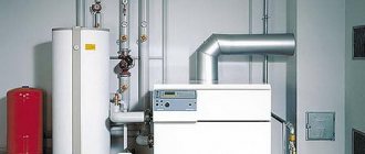
The thermal storage unit is a special thermally insulated tank directly connected to the heating boiler. Its device has the following features:
- The container in most cases has the shape of a vertically mounted cylinder, the body of which is made of durable stainless or black steel sheet.
- The inside of the tank is covered with a special protector to protect it from hot water or other coolant, as well as salts and acids dissolved in them.
- The outside of the tank has a layer of powder coating with increased heat resistance.
- On the outside, the container is hermetically sealed with a heat-insulating material with a layer of at least 10 cm. Re-foamed polyurethane foam with an internal PVC coating is used as insulation.
- Next, the heat-insulating layer is covered with a durable leatherette cover and a protective shell.
An example of a device and operating diagram of a heat storage tank Source stroyfora.ru
In this case, the useful volume of the tank can vary from 100 liters to 1 m³ or more. However, specimens larger than one cubic meter are rarely used to support the heating system of a private house. The main purpose of a heat accumulator for heating, using the example of a solid fuel unit, boils down to the following:
- Maintaining the nominal temperature of the coolant during the period when the boiler has already cooled down.
- Heating the unit at the optimal and convenient time, and not when the system begins to naturally cool down.
- Significant increase in the period between extreme firings of the boiler.
- Reducing and optimizing fuel consumption.
Helpful information! The excess thermal energy generated by the boiler is accumulated in a tank and then gradually used to maintain the optimal temperature of the coolant. Thus, the large inertia of the solid fuel unit is leveled out - the need to wait until the room is heated to the required comfortable level while it periodically cools down.
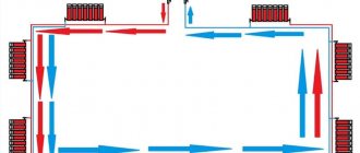
Detailed diagram of a heating system with a buffer heat storage Source prom.st
Operating principle, scope of application
The operation of a thermal storage device of the simplest type is carried out according to the following principle:
- From the heat exchange circuit of the unit, heated coolant flows into the upper pipe of the container.
- As the boiler operates, the tank is completely filled with coolant heated to the specified value.
- At the same time, from the opposite upper pipe the coolant flows into the batteries of the home heating system and other consumers. However, while the unit is operating, the temperature inside the tank does not fall, but, on the contrary, increases - if, of course, the heat storage device is correctly selected and matches the boiler power and consumer consumption.
- In this case, the coolant cooled in the system enters the lower inlet pipe of the tank, but without mixing with the upper heated layer, it enters the heating circuit of the boiler from the outlet pipe.
- When the tank is filled to the maximum level with heated coolant, the unit turns off.
- Next, the heat accumulator pumps coolant through the system using its own circulation pump.
Operating principle of a heat accumulator indicating the movement of the coolant Source altep.ua
- In this case, the hot phase is gradually replaced by a cooled one. However, a high-quality and well-designed heat storage device is capable of fully maintaining the specified heating of the coolant not only for many hours, but also, if necessary, for several days.
A heat accumulator for a heating system can be used not only in a circuit with a solid fuel boiler, but also with any other that runs on an alternative type of fuel - gas, electricity and even wind, solar and subsoil energy.
The scope of application of a thermal storage device is determined by the following range of its capabilities:
- The number of connected consumers depends on the presence of independent circuits and can vary from 4 to 20.
- The heat storage tank can be converted into an electric boiler by installing heating elements through the side flanges.
- The reservoir can be divided into separate interacting sectors using horizontal overlaps inside.
- An additional heat exchanger can be installed in the lower area of the tank to increase performance.
- To provide hot domestic water, a storage tank or an additional heat exchanger can be built into the tank.
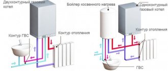
Diagram of a combined heating system with a heat accumulator Source evan.ru
Note! A thermal accumulator is especially relevant when the energy resource spent on heat generation has periodic or limited access. An example is solar and wind generators that do not function in cloudy and windless weather. It is also useful when the electric boiler is connected at a reduced rate, which is only possible during certain limited hours of the day.
Do-it-yourself installation recommendations
To lay the main natural circulation lines, it is better to use polypropylene or steel pipes. The reason is the large diameter, polyethylene Ø40 mm and more is too expensive. We make radiator hoses from any convenient material.
Advice. When assembling a gravity heating network made of metal-plastic, do not install compression fittings - they greatly reduce the internal passage.
An example of installing a two-pipe wiring in a garage.
How to make the wiring correctly and withstand all slopes:
- Start with markings. Mark the locations for installing batteries, connection points for connections, and routes for highways.
- Mark the routes on the walls with a pencil, starting from the distant batteries. Adjust the amount of inclination using a long building level.
- Move from the outer radiators to the boiler room. When you draw all the routes, you will understand at what level to install the heat generator. The inlet pipe of the unit (for cooled coolant) must be located at the same level or below the return line.
- If the firebox floor level is too high, try moving all the heaters up. Horizontal pipelines will rise next. As a last resort, make a recess under the boiler.
Laying a return line in a furnace room with a parallel connection to two boilers.
After marking, punch holes in the partitions and cut grooves for a hidden gasket. Then check the routes again, make adjustments and proceed with installation. Follow the same order: first secure the batteries, then lay the pipes towards the combustion chamber. Install an expansion tank with a drain pipe.
The gravity pipeline network is filled without problems; Mayevsky’s taps do not need to be touched. Just slowly pump water through the fill valve at the lowest point, all the air will go into the open tank. If any radiator remains cold after warming up, use a manual air vent.
Advantages and disadvantages
The use of a heat accumulator in a heating system for a private home has the following number of advantages:
- Significant savings in fuel resources. The generated heat is used to the maximum extent to heat the house.
- It becomes possible to use several energy resources for heating. For example, a solid fuel boiler is responsible for basic heat production, periodically heated at full power and charging the heat accumulator, and a compact electric or gas boiler is used for support in intermediate periods. In this case, heating circuits operating on alternative types of energy - solar panels and a wind generator - can be used as an additional source.
Heat accumulator with boiler, decoupling and consumers Source kotli.pro
See also: Catalog of companies that specialize in engineering systems (heating, water supply, sewerage and others) and related work
- Reliable protection against overheating of both the unit itself and all elements of the heating circuit. A correctly calculated heat storage device simply will not allow the temperature to rise above the set value.
- Reduced maintenance procedures in a given period - increasing the time between stages of fuel loading.
- Stabilization of the operation of the heating system as a whole - the absence of temperature changes during sudden cold snaps, which provides a more comfortable microclimate in the room.
- Providing the home with hot domestic water.
However, installing a heat storage module in a private heating system has not only advantages, but also often some disadvantages:
- The introduction of a heat accumulator is justified when the output power of the unit is at least 1.5-2 times higher than the heat demand of the living space.
- The operation of a thermal accumulator is characterized by high inertia. A lot of time passes from the moment of startup to the transition to the nominal state. And the larger the area of the heated room, the larger it is. Therefore, installing the module is only relevant in houses with permanent residence. For periodic visits, for example, on weekends in a country house, its use is not advisable.
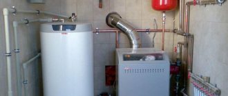
The heat accumulator is characterized by large dimensions and heavy weight when filled with coolant Source termopaneli59.ru
- The body of a heat accumulator, as a rule, has impressive dimensions, which somewhat complicates the task of transporting and installing it. In addition, because of this, the boiler room must have an additional space designated for its installation next to the boiler.
- The prices of a reliable branded heat storage device and the heating boiler itself are usually comparable, which significantly increases the final cost of the entire system. However, in the long term, long-term operation costs are recouped by significant savings in energy resources, extended service life of equipment and components, and provision of comfortable conditions in residential premises.
Reference! When choosing a heat storage device, you must make sure that there is a heat-insulating layer on the outside of the housing. If the purchased model does not have such coverage, the user will have to purchase and install it himself.
The heat accumulator must have a reliable thermal insulation layer Source indclimat.ru
Heat accumulator for heating boilers: parameters, installation features and where to buy
The inability to use relatively inexpensive natural gas as an energy source for heating homes forces homeowners to look for other acceptable solutions. So, in regions where there are no special problems with the procurement or purchase of firewood, solid fuel boilers come to the rescue. It also happens that the only alternative is electrical energy. In addition, new technologies are increasingly being used that make it possible to direct the energy of solar radiation to heating needs.
Heat accumulator for heating boilers
All these approaches are not without significant drawbacks. Thus, these include unevenness and pronounced periodicity in the supply of thermal energy. In the case of an electric boiler, the main negative factor will be the high cost of energy consumed. It is obvious that to significantly increase the efficiency of the heating system, improve the efficiency and uniformity of its operation, and simplify operational operations as much as possible would help by including in the general scheme a special device that would accumulate currently unclaimed thermal energy and release it as needed. This is exactly the function that a heat accumulator for heating boilers performs.
The main purpose of the heating system heat accumulator
- The simplest heating system with a solid fuel boiler has a pronounced cyclical operation. After loading firewood and igniting it, the boiler gradually reaches maximum power, actively transferring thermal energy to the heating circuits. But as the load burns out, the heat transfer begins to gradually decrease, and the coolant distributed through the radiators cools down.
The operation of a conventional solid fuel boiler is characterized by a pronounced alternation of peaks and “troughs” in the production of thermal energy.
It turns out that during the period of peak heat production it may remain unclaimed, since a customized heating system equipped with thermostatic control will not take in excess. But during the period when the fuel burns out and, moreover, when the boiler is idle, there will be a clear lack of thermal energy. As a result, part of the fuel potential is simply wasted, but at the same time, the owners have to load firewood quite often.
To a certain extent, the severity of this problem can be reduced by installing a long-burning boiler, but it cannot be completely removed. The discrepancy between the peaks of heat production and its consumption can remain quite significant.
- In the case of an electric boiler, the high cost of energy consumption comes to the fore, which forces owners to think about maximizing the use of equipment during periods of preferential night tariffs and minimizing consumption during the daytime.
Benefits of using differentiated electricity tariffs
With a competent approach to electricity consumption, preferential tariffs can bring very significant cost savings. This is described in detail in a special publication on the portal dedicated to two-tariff electricity meters .
An obvious solution arises - to accumulate thermal energy at night in order to achieve its minimum consumption during the day.
- The periodicity of thermal energy generation is even more pronounced in the case of using solar collectors. Here there is a dependence not only on the time of day (at night the intake is generally zero).
The operation of the solar collector is very dependent on both the time of day and the weather.
Heating peaks on a bright sunny day or in cloudy weather cannot be compared. It is clear that it is impossible to directly make your heating system dependent on the current “whims” of nature, but you also don’t want to neglect such a powerful additional source of energy. Obviously some kind of buffer device is required.
These three examples, with all their diversity, are united by one common circumstance - a clear discrepancy between the peaks of thermal energy production and its rational, uniform use for heating needs. To eliminate this imbalance, a special device called a heat accumulator (thermal accumulator, buffer tank) is used.
Prices for heat accumulators Hajdu
heat accumulator Hajdu
The principle of its operation is based on the high heat capacity of water. If a significant volume of it is heated to the required level during the period of peak thermal energy supply, then for a certain period this accumulated energy potential can be used for heating needs. For example, if we compare thermophysical indicators, just one liter of water, when cooled by 1°C, can warm up a cubic meter of air by as much as 4°C.
The heat accumulator is always a volumetric reservoir with effective external thermal insulation, connected to the heat source circuit(s) and heating circuits. It is better to consider the simplest scheme using an example:
A visual demonstration of the operating principle of a simple heat accumulator
The simplest heat accumulator (TA) in design is a vertically located volumetric tank, into which four pipes are embedded on two opposite sides. On the one hand, it is connected to the solid fuel boiler circuit (SFC), and on the other, to the heating circuit distributed throughout the house.
After loading and igniting the boiler, the circulation pump (Nk) of this circuit begins to pump coolant (water) through the heat exchanger. Cooled water enters the boiler from the lower part of the TA, and heated water arrives into the upper part. Due to the significant difference in the density of cooled and hot water, there will be no active mixing in the tank - during the combustion of the fuel fill, the heat exchanger will gradually be filled with hot coolant. As a result, if the parameters are correctly calculated, after the stored fuel has completely burned out, the container will be filled with hot water, heated to the calculated level. All potential energy of the fuel (minus, of course, the inevitable losses reflected in the efficiency of the boiler) is converted into heat, which is accumulated in the heating element. High-quality thermal insulation allows you to maintain the temperature in the tank for many hours, and sometimes even days.
Stage two – the boiler is not working, but the heating system is functioning. Using the heating circuit's own circulation pump, coolant is pumped through pipes and radiators. The intake is made from above, from the “hot” zone. Intensive independent mixing is again not observed - for the reason already mentioned, and hot water enters the supply pipe, cooled water returns from below, and the tank gradually releases its heat in the direction from bottom to top.
In practice, during the heating process of the boiler, the selection of coolant into the heating system, as a rule, does not stop, and the heating system will only accumulate excess energy, which currently remains unclaimed. But with the correct calculation of the parameters of the buffer tank, not a single kilowatt of thermal energy should be wasted, and by the end of the boiler firing cycle, the TA should be “charged” to the maximum extent.
It is clear that the cyclical operation of such a system with an installed electric boiler will be tied to preferential night rates. The control unit's timer will turn the power on and off at a set time in the evening and morning, and during the day the heating circuits will be powered only (or predominantly) from the heat accumulator.
Design features and basic connection diagrams for various heat accumulators
So, a heat accumulator is always a volumetric vertical cylindrical tank, which has highly effective thermal insulation and is equipped with pipes for connecting heat generation and consumption circuits. But the internal design may vary. Let's consider the main types of existing models.
Main types of heat accumulator designs
Heat accumulator with direct connection of thermal energy production and consumption circuits
1 – The simplest type of heat exchanger design. This implies a direct connection of both heat sources and consumption circuits. Such buffer tanks are used in the following cases:
- If the boiler and all heating circuits use the same coolant.
- If the maximum permissible coolant pressure in the heating circuits does not exceed that of the boiler and the heating unit itself.
In cases where the requirement cannot be met, the heating circuits can be connected through additional external heat exchangers
- If the temperature in the supply pipe at the outlet of their boiler does not exceed the permissible temperature in the heating circuits.
However, this requirement can also be bypassed when installing mixing units with three-way valves on circuits that require a lower temperature difference.
Heat accumulator with built-in heat exchanger
2 – The heat accumulator is equipped with an internal heat exchanger located in the lower part of the tank. The heat exchanger is usually a spiral twisted from a stainless steel pipe, regular or corrugated. There may be several such heat exchangers.
This type of TA is used in the following cases:
- If the pressure and achieved temperature of the coolant in the heat source circuit significantly exceed the permissible values for the consumption circuits and for the buffer tank itself.
- If there is a need to connect several heat sources (according to the bivalent principle). For example, a solar system (solar collector) or a geothermal heat pump comes to the aid of the boiler. Moreover, the lower the temperature pressure of the heat source, the lower its heat exchanger should be placed in the heat exchanger.
- If different types of coolant are used in the heat source and consumption circuits.
Unlike the first scheme, this heat exchanger is characterized by active mixing of the coolant in the container - heating occurs in its lower part, and less dense hot water tends upward.
The diagram in the center of the HA shows a magnesium anode. Due to the lower electrical potential, it “pulls” ions of heavy salts onto itself, preventing scale from overgrowing the internal walls of the tank. Subject to periodic replacement.
Heat accumulator with built-in hot water flow heat exchanger
3 – The heat accumulator is supplemented with a flow-through hot water supply circuit. Cold water enters from below, supply to the hot water tap point, respectively, from below. Most of the heat exchanger is located in the upper part of the heat exchanger.
This scheme is considered optimal for conditions where hot water consumption is sufficiently stable and uniform, without pronounced peak loads. Naturally, the heat exchanger must be made of metal that meets food water consumption standards.
The rest of the scheme is similar to the first one, with direct connection of heat generation and consumption circuits.
Heat accumulator with built-in hot water tank
4 – Inside the heat accumulator there is a tank to create a supply of hot water for domestic consumption. In fact, this scheme resembles a built-in indirect heating boiler.
The use of such a design is fully justified in cases where the peak of thermal energy production by the boiler does not coincide with the peak of hot water consumption. In other words, when the current household structure in the house involves massive, but rather short-term consumption of hot water.
All of the listed schemes can vary in various combinations - the choice of a specific model depends on the complexity of the heating system being created, the number and type of body sources and consumption circuits. Please note that most heat accumulators have many outlet pipes spaced vertically.
The vertically spaced connection pipes for the circuits allow optimal use of the temperature gradient formed in the heat accumulator
The fact is that with any scheme, a temperature gradient (difference in temperature pressure in height) is formed one way or another inside the buffer tank. It becomes possible to connect heating system circuits that require different temperature conditions. This greatly facilitates the final thermostatic control of heat exchange devices (radiators or underfloor heating), with minimal unnecessary energy losses and reduced load on the control devices.
Typical connection diagrams for heat accumulators
Now we can consider the basic schemes for installing heat accumulators in a heating system.
| Illustration | Brief description of the scheme |
| The temperature and pressure are the same in the boiler and in the heating circuits. The coolant requirements are the same. A constant temperature is maintained at the boiler outlet and in the heat exchanger. On heat exchange devices, adjustment is limited only to a quantitative change in the coolant passing through them. | |
| The connection in the heat accumulator itself, in principle, repeats the first diagram, but the adjustment of the operating modes of the heat exchange devices is carried out according to a qualitative principle - with a change in the temperature of the coolant. For this purpose, thermostatic mixing units, for example, three-way valves, are included in the circuit. This scheme allows the most rational use of the potential accumulated by the heat accumulator, that is, its “charge” will last for a longer time. | |
| This scheme, with coolant circulation in a small boiler circuit through a built-in heat exchanger, is used when the pressure in this circuit exceeds the permissible limit in heating devices or in the buffer tank itself. The second option is that different coolants are used in the boiler and in the heating circuits. | |
| The initial conditions are similar to scheme No. 3, but an external heat exchanger is used. Possible reasons for this approach: - the heat exchange area of the built-in “coil” is not enough to maintain the required temperature in the body accumulator. – previously a heat exchanger had already been purchased without an internal heat exchanger, and the modernization of the heating system required exactly this approach. | |
| Scheme with the organization of flowing hot water through a built-in spiral heat exchanger. Designed for uniform consumption of hot water, without peak loads. | |
| This scheme, using a heat accumulator with a built-in tank, is designed for peak hot water consumption, but not highly positive. After using up the created reserve and, accordingly, filling the container with cold water, heating to the required temperature can take quite a long time. | |
| A bivalent circuit that allows you to use an additional source of thermal energy in the heating system. In this case, the option with connecting a solar collector is shown in a simplified manner. This circuit is connected to the heat exchanger at the bottom of the heat accumulator. Typically, such a system is designed in such a way that the main source is the solar collector, and the boiler is turned on as needed, for reheating, when there is insufficient energy from the main one. The solar collector, of course, is not a dogma - there may be a second boiler in its place. | |
| A scheme that can be called multivalent. In this case, the use of three sources of thermal energy is shown. The role of the high-temperature boiler is played by the boiler, which, again, can only play an auxiliary role in the overall heating scheme. Solar collector - similar to the previous diagram. In addition, another low-temperature source is used, which, at the same time, is stable and independent of the weather and time of day - a geothermal heat pump. The lower the temperature pressure from the connected energy source, the lower the location of its connection to the heat accumulator. |
Of course, the diagrams are given in a very simplified form. But in fact, connecting a heat accumulator to complex, branched systems, with different heating circuits, and even receiving heat from sources of different power and temperature, requires highly professional design with thermal engineering calculations, using many additional control devices.
One example is shown in the figure:
Example of a system with multiple heat sources and different heating and DHW circuits
1 – solid fuel boiler.
2 – electric boiler, which turns on only as needed and only during the period of validity of the preferential tariff.
3 – special mixing unit in the high-temperature boiler circuit.
4 – solar station, solar collector, which on fine days can act as the main source of thermal energy.
5 – heat accumulator, to which all heat generation and consumption circuits converge.
6 – high-temperature heating circuit with radiators, with adjustment of modes according to the quantitative principle - only using shut-off valves.
7 – low-temperature heating circuit – “warm floor”, which necessarily provides for high-quality regulation of the heating temperature of the coolant.
8 – flow-through hot water supply circuit, equipped with its own mixing unit for high-quality regulation of the temperature of domestic hot water.
In addition to all of the above, the heat accumulator can have its own electric heaters – heating elements – built into it. Sometimes it is beneficial to maintain a given temperature with their help without, for example, once again resorting to unscheduled lighting of a solid fuel boiler.
Additional heating element equipped with its own thermostatic system
Special additional heating elements can be purchased separately - their mounting thread is usually adapted to the connection sockets available on many models of heat accumulators. Naturally, connecting electrical heating will require the installation of an additional thermostatic unit, which will ensure that the heating elements are turned on only when the temperature in the heater drops below the level set by the user. Some heaters are already equipped with a built-in thermostat of this type.
Prices for S-Tank heat accumulators
Thermal accumulator S-Tank
Video: Recommendations from a specialist for creating a heating system with a solid fuel boiler and heat accumulator
What to consider when choosing a heat accumulator
Of course, it is recommended to select a heat accumulator at the stage of designing a home heating system, guided by the calculation data of specialists. However, circumstances vary, and you still need to know the basic criteria for evaluating such a device.
- The capacity of this buffer tank will always come first. This value is calculated in accordance with the parameters of the system being created, the power of the boiler, the required amount of energy for heating needs, and hot water supply. In a word, the container must be such as to ensure the accumulation of all currently excess heat, preventing its loss. Some rules for calculating capacity will be discussed below.
- Naturally, the dimensions of the product and its weight directly depend on the capacity. These parameters are also decisive - it is not always possible and not everywhere to place a heat accumulator of the required volume in a dedicated room, so the issue must be thought through in advance. It happens that large volume tanks (over 500 liters) do not fit through standard doorways (800 mm). When estimating the mass of TA, it must be taken into account together in the entire volume of water of a completely filled device.
- The next parameter is the maximum permissible pressure in the heating system being created or already functioning. A similar TA indicator should be, in any case, no lower. This will depend on the thickness of the walls, the type of material used, and even the shape of the container. Thus, in buffer tanks designed for pressures above 4 atmospheres (bar), the upper and lower lids usually have a spherical (toroidal) configuration.
The heat accumulator is made of stainless steel, with toroidal-shaped covers, enclosed in a thermal insulating casing.
- Material for making the container. Carbon steel tanks with anti-corrosion coating are cheaper. Stainless steel containers are, of course, more expensive, but their warranty period is also much longer.
- Availability of additional built-in heat exchangers for heating or hot water supply circuits. Their purpose has already been mentioned above - models are selected depending on the overall complexity of the heating system.
- Availability of additional options - the possibility of installing heating elements, installing instrumentation, safety devices - safety valves, air vents, etc.
- The thickness and quality of the external thermal insulation of the TA body must be assessed so that you do not have to deal with this issue yourself. The better the tank is insulated, the longer the “thermal charge” will naturally be stored in it.
Features of installation of heat accumulators
Installing a heat accumulator requires compliance with certain rules:
- All connected circuits must be connected with threaded couplings or flanges. Welded joints are not allowed.
- The connected pipes must not exert any static load on the TA pipes.
- It is recommended to install shut-off valves on all pipes connected to the TA.
- Visual temperature monitoring devices (thermometers) are installed at all used inputs and outputs.
- There should be a drain valve at the lowest point of the TA or on the pipe in close proximity to it.
- Filters for mechanical water purification – “mud collectors” – are installed on all pipes entering the heat accumulator.
- Many models have a pipe on top for connecting an automatic air vent. If there is none, then the air vent must be installed on the uppermost outlet pipe.
- A pressure gauge and a safety valve are to be installed in the immediate vicinity of the heat accumulator.
- Making any independent changes to the design of the heat accumulator that are not specified by the manufacturer is strictly prohibited.
- Installation of TA should be carried out only in a heated room, eliminating the possibility of freezing of the liquid.
- A tank filled with water can have a very significant mass. The platform must be able to withstand such a high load. Often for these purposes it is necessary to add a special foundation.
- No matter how the heat accumulator is installed, free access to the inspection hatch must be ensured.
Carrying out simple calculations of heat accumulator parameters
As mentioned above, a comprehensive calculation of a heating system with several circuits for the production and consumption of thermal energy is a task that can only be accomplished by specialists, since many diverse factors have to be taken into account. But certain calculations can be carried out on your own.
For example, a solid fuel boiler is installed in the house. Its power generated at full fuel load is known. The combustion time of a full load of firewood was determined experimentally. You are planning to purchase a heat accumulator, and you need to determine how much volume is required to ensure that all the heat generated by the boiler is effectively used.
Let's take the well-known formula as a basis:
W = m × c × Δt
W is the amount of heat required to heat a mass of liquid ( m ) with a known heat capacity ( c ) by a certain number of degrees ( Δt ).
From here it is easy to calculate the mass:
m = W / (s × Δt)
It doesn’t hurt to take into account the boiler efficiency ( k ), since energy losses are inevitable one way or another.
W = k × m × c × Δt, or
m = W / (k × c × Δt)
Now let's look at each of the values:
- m is the desired mass of water, from which, knowing the density, it will be easy to determine the volume. It would not be a big mistake to calculate at the rate of 1000 kg = 1 m³ .
- W is the excess amount of heat generated during the boiler firing period.
It can be defined as the difference in the energy values generated during the combustion of the fuel deposit and spent during the same period on heating the house.
The maximum power of the boiler is usually known - this is the nameplate value, designed for optimal solid fuel water. It shows the amount of thermal energy generated by the boiler per unit of time, for example, 20 kW.
Any owner always knows quite accurately how long it takes for his fuel fill to burn out. Let's say it will be 2.5 hours.
Next, you need to know how much energy can be spent heating the house at this time. In a word, it is necessary to determine the thermal energy needs of a particular building to ensure comfortable living conditions.
Such a calculation, if the value of the required power is unknown, can be done independently - for this there is a convenient algorithm given in a special publication on our portal.
How to independently carry out thermal calculations for your own home?
Information about the amount of thermal energy required to heat a house is often in demand - when choosing equipment, arranging radiators, and when carrying out insulation work. The reader can get acquainted with the calculation algorithm, including a convenient calculator, by clicking on the link to the publication dedicated to the requirements for installing gas boilers .
For example, heating a house requires 8.5 kW of energy per hour. This means that in 2.5 hours of combustion of the fuel filler the following will be obtained:
20 × 2.5 = 50 kW
During the same period the following will be spent:
8.5 × 2.5 = 21.5 kW
Excess heat that needs to be stored in the heat accumulator:
W = 50 – 21.5 = 28.5 kW
- k – efficiency of the boiler installation. It is usually indicated in the product passport as a percentage (for example, 80%) or as a decimal fraction (0.8).
- c is the heat capacity of water. This is a tabular value that is equal to 4.19 kJ/kg×°C or 1.164 Wh/kg×°C or 1.16 kW/m³×°C.
- Δt is the temperature difference by which the water needs to be heated. It can be determined experimentally for your system by measuring the values on the supply and return pipes when the system is operating at maximum power.
Let's assume that this value is
Δt = 85 – 60 = 35 °C
So, all the values are known, and all that remains is to substitute them into the formula:
m = 28500 / (0.8 × 1.164 × 35) = 874.45 kg.
Thus, in order to fully retain all the heat generated by the boiler when it is operating at full power, 875 kg of water will be required, that is, a capacity of approximately 0.875 m³.
The same approach can be applied if the volume of a heat accumulator connected to an electric boiler is calculated. The only difference is that for the calculation it is not the combustion time that is taken, but the time interval of the preferential tariff, for example, from 23.00 to 6.00 = 7 hours. To “unify” this value, it can be called, for example, “boiler activity period.”
To simplify the task for the reader, below is a special calculator that will allow you to quickly calculate the recommended volume of a heat accumulator for an existing (planned for installation) boiler.
Calculator for calculating the required volume of a heat accumulator
Go to calculations
The resulting value is rounded up and becomes a guideline when selecting the optimal heat accumulator model. They are presented in various volumetric designs in special stores.
Advantages and disadvantages of including a heat accumulator in the heating system
So, summing up the results of the publication, we will briefly formulate the “pros” and “cons” of using heat accumulators.
The advantages include the following:
- Energy savings are achieved, especially when applied to solid fuels - the generated heat is used to the maximum extent. The efficiency of the boiler and the entire heating system as a whole increases.
- Boilers and other elements of the heating system receive reliable protection against overheating.
- The need for intervention in the operation of the system is reduced to the possible minimum, and the number of solid fuel loads is reduced.
- The entire system operates more smoothly and is easier to control and make precise adjustments. Provides stable installed heating in all areas of the house.
- It becomes possible to connect alternative energy sources. With the right approach, this provides serious savings in money. For example, during the daytime the main load falls on the solar station; at night, while the preferential tariff is in effect, the heat pump takes over the baton, and a compact gas boiler compensates for the possible shortage.
- By installing a heat accumulator, you can simultaneously solve the problem of hot water supply to your home.
disadvantages , but they should also be mentioned:
- The installation will make some sense if the power of the boiler or other heat sources is significantly, at least twice, higher than the calculated values of the required thermal energy for heating the home.
- A system with a heat accumulator always has a very high inertia, that is, a lot of time can pass from the moment of start-up to reaching the design operating mode. There is no point in using it in heating systems where rapid heating of rooms is required, for example, in country houses that are visited by the owners only from time to time in winter.
- The equipment, as a rule, is very bulky, which creates many problems during its transportation, unloading, bringing it into premises and installation. Since a prerequisite is the installation of the heat exchanger in close proximity to the boiler, the boiler room will require a very large area.
- Heat accumulators belong to the category of expensive purchases - their price is quite comparable, and often even exceeds the cost of boilers. True, there is a high probability that the costs will quickly be recouped by savings on energy resources.
True, the last of the listed disadvantages encourages craftsmen to develop and install their own models of heat accumulators.
Is it difficult to make a heat accumulator yourself?
Probably, the Russian amateur master can do anything! For example, technological recommendations for self-manufacturing a heat accumulator are given in a special publication on our portal.
Video: advantages of a heating system with a built-in heat accumulator
Varieties
Depending on the characteristics of the device, the properties it defines and its purpose, the following 4 main types of heat accumulators for heating systems are distinguished:
- The simplest buffer containers without partitions inside.
The heat storage tank, which is hollow inside, is filled with one coolant circulating between the thermal circuit of the boiler and the heat consumers. Installed in the following situations:
- The heating system (boiler, radiators and other consumers) operates on the same coolant.
- The limit value of pressure in the equipment is not higher than the same parameter for the boiler and storage tank.
- The heating level of the coolant at the outlet of the boiler circuit does not exceed the maximum permissible consumer temperature.
However, if the last requirement cannot be met, installing a buffer tank is still possible. To do this, 3-way valves are introduced into the circuit, which makes it possible to reduce the heating level of the hot coolant entering the consumer circuit by mixing it with the cooled coolant supplied from the return line.
The simplest buffer thermal storage device Source ktl.by
- With built-in heat exchanger at the bottom.
Inside the tank there is an additional heat exchange circuit made of stainless steel pipe. Depending on the purpose, the number of such coils can be from 1 to 3. This allows you to create several independent circuits with different coolants and their characteristics.
Application cases:
- When the pressure and heating level of the coolant exceed the permissible values of similar parameters of the receivers.
- When it is possible to use several heat generators - additional boilers, as well as due to sunlight, wind or geothermal sources, etc. Moreover, the lower the heating level of the coolant, the lower the circuit through which it circulates should be located in the tank.
- Heat accumulators of this type are also used for individual heating of a house, when one type of coolant is used in the heat exchange circuit, and another is used in the consumption system.
The design of a heat accumulator with a lower coil location Source forvardplast.ru
The best manufacturers
If you don’t know which company’s heat tanks are better in terms of price and set of characteristics, then try to give preference to models from the most well-known brands. In most cases, such devices from domestic or foreign manufacturers are of good quality and work properly for a long period.
Popular manufacturers:
- Parpol (Bulgaria);
- S-Tank (Belarus);
- Nibe (Sweden);
- Tesy (Bulgaria);
- Hajdu (Hungary);
- Sunsystem (Bulgaria);
- Stiebel Eltron (Germany).
Criterias of choice
When choosing a heat accumulator for a home heating system, the following criteria should be taken into account:
- Capacity of the container. It is calculated taking into account the characteristics of the system, the power of the unit, and the consumption of domestic hot water.
- Dimensions and weight. They must correspond to the strength of the base on which they will be installed, as well as the characteristics of transportation and installation work.
- Limit pressure level. It must be no lower than the same parameter in the system. They determine the thickness of the walls, the material from which they are made, as well as the geometry and design features of the tank.
- Case material. Products made from carbon steel alloy are cheaper, but also have a shorter service life due to their susceptibility to corrosion. Stainless steel models are more expensive, but are durable.
- Additional heat exchangers. The number is determined by the presence of connected circuits and the complexity of the circuit.
The main feature of the difference between heat accumulators is capacity Source termico.com.ua
- Functional. Depending on the capabilities, manufacturers equip their products, in addition to the basic parameters, with various additional functions - installation of heating elements, installation of control and measuring equipment, installation of automation and safety devices, such as, for example, air valves, thermostats, etc.
- The quality of the thermal insulation layer. Not only the thickness of the coating is taken into account, but also the type of material used. The longer the tank stores heat, the more cost-effective it is in a private heating system.
On a note! It is better to purchase a thermal storage device only at a specialized retail outlet. The product must be branded, have a certificate, a guarantee and a full instruction manual.
Basic calculations
Of course, the more capacious the heat accumulator, the longer it can compensate for the downtime of the heating boiler. However, the cost of the tank and maintenance costs increase in direct proportion to its volume. Therefore, it is important to find a compromise way in resolving the issue of providing the system with a high-quality heat storage device. To do this, a calculation is used that primarily takes into account three main factors:
- Heat loss rate.
- House area.
- Heat generator downtime.
Using a housing area of 100 m² as an example, we will analyze the rules for calculating the capacity of a heat storage device. The following input data is used (in reality their values may be slightly different):
- The amount of heat for heating the house is 10 kW.
- The period of inactivity of the unit is 10 hours.
- The operating temperature of the coolant is 70 °C.
- The total amount of heat that the tank must give off to maintain the room temperature during the entire period of inactivity = 10 hours x 10 kW = 100 kW - this is exactly the amount of energy it must accumulate.
- The maximum heating level of the coolant is 90 °C.
Prices: summary table
| Model | Volume, l | Allowable operating pressure, bar | Cost, rub |
| Sunsystem PS 200, Bulgaria | 200 | 3 | 38 000 |
| Hajdu AQ PT 500 C, Hungary | 500 | 3 | 33 000 |
| S-TANK AT PRESTIGE 300, Belarus | 300 | 6 | 39 000 |
| ACV (ATsV) LCA 750 1 CO TP, Belgium | 750 | 8 | 178 000 |
Video description
Video example on how to calculate a heat accumulator:
Next, you need to calculate the mass (volume) of water that would be capable of holding such an amount of thermal energy, using the following formula:
- M = Ke / 0.0012 Δt
- M – mass of water, kg,
- Ke – amount of stored energy, kW,
- Δt – temperature difference between the heated coolant and cooled coolant in the system, °C,
- 0.0012 – heat capacity of water, kW/kg °C.
Substituting the input data into the formula, we get:
100/0.0012 (90-70) = 4166 kg or approximately 4 m³.
However, in practice such large containers are rarely used. Therefore, in order to reduce the costs of their installation and maintenance, downtime can be reduced by half, and the coolant cooling level can be reduced to an acceptable 500C. Then, to maintain comfortable heat in a house with good thermal insulation, a capacity of 1000 liters will be sufficient.
Connection features
The connection diagram of the heat accumulator tank depends on its design features, the level of complexity of the heating system, connected consumers and general decoupling. However, in the simplest case, when a heat exchange hollow buffer is installed, which has only 2 pairs of inlet and outlet pipes - bottom and top - a standard scheme is used
It assumes the same pressure and circulation of the same coolant in the unit circuit and consumers. To regulate the temperature and performance in the circuit, one circulation pump is installed on the return lines - in front of the tank and after it in front of the unit.
Sometimes a pair of 3-way valves are added to the circuit, mixing cold and hot flows, to regulate the heating level. In one case, overheating of the consumer is excluded, in the other, overcooling of the heat exchange circuit of the unit and harmful consequences due to the formation of condensate are prevented.
Briefly about the main thing
A heat accumulator is a special thermally insulated container, directly connected to the heat exchange circuit of the boiler and ensuring the accumulation of heat, and then its uniform release into the heating system. It works on the principle of accumulation, containment and subsequent distribution of thermal energy to consumers. Its main functions:
- Maintaining the operating level of heating of the coolant during boiler downtime.
- Reducing energy costs.
- Extending the period between operating cycles of the unit.
- Start-up and maintenance of the boiler at a time convenient for the user and energy consumption.
At the same time, a heat accumulator for a boiler has the following main advantages - savings, protection against overheating, connection of additional heat sources, provision of hot water; disadvantages - inertia, takes up a lot of space, high cost. It is classified into 4 types - buffer, with lower and upper coils, with a built-in boiler.
When choosing, a number of parameters are taken into account - capacity, body material, dimensions, weight, design pressure, functionality, number of heat exchangers, insulation quality. Also, before purchasing a tank, it is important to correctly calculate its capacity, which depends on the area of the house, the specifics of the system and equipment.
Ratings 0
Online calculator
*If the calculator shows 0 (zero), it means you have no excess energy to accumulate.
Explanations:
The rated power of the boiler is indicated by the manufacturer. If the documents for the equipment have not been preserved, you can find the specifications on the Internet.
The power needed to heat your home. It is calculated by specialists using a complex form, which includes: the volume of the room, the heating system, and the energy efficiency of the entire house.
Supply and return temperatures. If the system does not have thermometers installed, it can be removed with any heat remover.