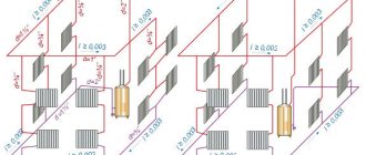
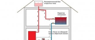
Diagram of a heating system for a Tichelmann loop house
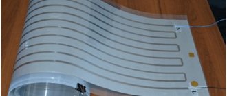
Basically, it is planned to lay the heating pipeline under the floor covering in tunnels, covered in thermal insulation shells, so as not to destroy the structure due to overheating. Floors are made either on joists, or a thick screed underfloor heating is laid. Mainly flexible piping is used, elbow fittings are not used.
In modern houses, the Tichelman loop loses its main drawback - the difficulty of laying a closed circle on the distributor. Can be easily used in small and large areas, when installed under the floor. Recently, in-floor convectors under high windows have been increasingly used.
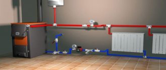
One of the most popular types of heating systems in our time is the so-called Tichelman loop. This scheme is quite simple, but when performing wiring in this case, of course, you need to adhere to a certain technology. Before installing such a system, you should definitely draw up a detailed project, making all the necessary calculations. The Tichelmann loop heating circuit is actually very simple. In this case, the supply pipe is pulled in the usual way - that is, from the boiler to the last radiator.
The Tichelman loop will be a suitable circuit for connecting convectors, more economical and stable compared to a beam circuit with a large number of more than 4 pieces. Private houses are always of a compressed layout, there are no long lines to heating devices - increased hydraulic resistance is not found in the diagrams.
Recommendations to make calculations of the heating system are unnecessary, since it will not be possible to independently determine the exact heat loss of the building, and the equipment used is standard; all that remains is to choose the appropriate one from a couple of samples.
To determine the diameter of the pipes for the Tichelman loop, you can use tabular data depending on the diameter on the required energy. With heat loss up to 15 kW m sq.
Application area
They are also used for the main lines in most cases - up to about 8 radiators in a ring. With heat losses from 15 to 27 kW to sq. m. The diameter of the pipeline in the loop can be reduced in accordance with the calculation. And with the condition stated above.
What is the system and how is it installed
In any case, a minimum diameter of 16 mm is laid to the last radiator along the supply. For heated area up to sq. m. It is advisable to make a common riser and lay a separate Tichelman loop ring for each floor
It is important to take into account that energy losses for each floor will differ significantly; in accordance with this, radiators are selected, as well as pipe diameters
Separate schemes in floors will allow you to balance one floor relative to another and significantly simplify system setup
It’s just important not to forget to include a balancing valve in the ride circuit for each floor.
How to calculate the required pipe diameter?
Naturally, in the process of designing a heating system diagram in a specific architectural object, it is necessary to decide what the diameter of the pipes in the structure should be. In this case, the calculation of general heat and power indicators is assumed. This must be done first, since otherwise the installation of heating will be difficult. So, in the process of determining the diameter of the pipes, we calculate the power of the structure. It is necessary to determine the following parameters in advance:
- volume of the house;
- temperature difference indoors and in the environment;
- standard heat loss coefficient, which in turn directly depends on how insulated the architectural volume as a whole is.
Scheme of a two-pipe system
Regarding the coefficient, there are already predetermined numbers that depend on the degree of thermal insulation of the architectural object. So, if there is minimal thermal insulation or it is completely absent, then the coefficient is 3 or 4. In the case of facing a building with brick, this indicator varies in the range from 2 to 2.9. Assuming an average level of heat insulation in the premises, a coefficient with a value of about 1.8 is proposed. In conclusion, it is worth saying that if the house is insulated with high-quality building materials, and also provided that double-glazed windows and modern doors have been installed at all entrances to the building, the heat loss coefficient is minimal - no more than 0.9.
After the calculations described above, it is necessary to determine at what speed the coolant will move through the pipes. The traditional range of values for this parameter is from 0.36 to 0.7 meters per second. Experts call these frameworks optimal. As a rule, pipe diameters around 26 millimeters are most suitable for both the return and supply lines. To connect radiators to the system, experts recommend using 16-millimeter pipes.
Is it worth installing it yourself?
As can already be understood from all of the above, the Tichelman Loop heating has a fairly simple design.
In any case, it will not be more difficult to assemble than a regular dead-end system. However, it is worth considering that the Tichelman loop is most often installed in very large houses. The assembly of heating systems in such buildings in itself has a lot of nuances. In addition, the calculation of communications for such an object should be made as accurate as possible. In this case, simply taking average values (10 kW boiler per 1 m2 of room, pipe diameters 26 and 16) will not work. It will be quite difficult to make correct calculations using tables and even using appropriate programs on your own. Therefore, it is still worth hiring specialists to design and install the Tichelman Loop system in a large house. Our ancestors slept differently than we do. What are we doing wrong? It’s hard to believe, but scientists and many historians are inclined to believe that modern man sleeps completely differently than his ancient ancestors. Initially.
These 10 little things a man always notices in a woman Do you think your man doesn’t understand anything about female psychology? This is wrong. Not a single little thing can be hidden from the gaze of a partner who loves you. And here are 10 things.
7 Body Parts You Shouldn't Touch with Your Hands Think of your body as a temple: you can use it, but there are some sacred places that you shouldn't touch with your hands. Research showing.
20 photos of cats taken at the right moment Cats are amazing creatures, and perhaps everyone knows this. They are also incredibly photogenic and always know how to be in the right place at the right time.
15 Cancer Symptoms Women Most Often Ignore Many signs of cancer are similar to symptoms of other diseases or conditions, which is why they are often ignored.
Pay attention to your body. If you notice
How to look younger: the best haircuts for those over 30, 40, 50, 60 Girls in their 20s don’t worry about the shape and length of their hair. It seems that youth is created for experiments with appearance and daring curls. However, already last.
Traditionally used heating schemes
- Single-pipe. The coolant circulates through one pipe without the use of pumps. On the main line, radiator batteries are connected in series; from the very last, the cooled medium (“return”) is returned to the boiler through a pipe. The system is simple to implement and economical due to the need for fewer pipes. But the parallel movement of flows leads to a gradual cooling of the water; as a result, the media arrives at the radiators located at the end of the series chain significantly cooled. This effect increases with increasing number of radiator sections. Therefore, in rooms located near the boiler it will be excessively hot, and in remote ones it will be cold. To increase heat transfer, the number of sections in the batteries is increased, different pipe diameters are installed, additional control valves are installed, and each radiator is equipped with bypasses.
- Two-pipe. Each radiator battery is connected in parallel to the direct supply of hot coolant and the “return” pipes. That is, each device is equipped with an individual return outlet. With the simultaneous discharge of cooled water into the common circuit, the coolant is returned to the boiler for heating. But at the same time, the heating of heating devices gradually decreases as they move away from the heat supply sources. The radiator, located first in the network, receives the hottest water and is the first to return the coolant to the “return” circuit, and the radiator located at the end receives the coolant last with a lower heating temperature and is also the last to return water to the return circuit. In practice, in the first device the circulation of hot water is the best, and in the last the worst. It is worth noting the increased price of such systems compared to single-pipe systems.
Both schemes are justified for small areas, but are ineffective for extended networks.
An improved two-pipe heating scheme is the Tichelman heating scheme. When choosing a specific system, the determining factors are the availability of financial capabilities and the ability to provide the heating system with equipment that has the optimal required characteristics.
Pipe system
Both the upper and lower wiring of the Tichelman loop are usually performed with PPR pipes. If concealed piping is required, a PEX system with push-on fittings is recommended. If pipes are laid in dense foundations, a thermal insulation shell should be used.
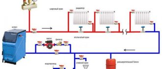
The Tichelman heating system for a one-story house is extremely simple. The coolant supply pipeline runs from the heating unit along the entire radiator network. The nominal diameter of the pipe is maintained until the penultimate radiator in the row, after which a transition is made to the radiator connection diameter, usually 20 mm polypropylene or 16 mm PEX. The return current pipeline is laid in the same order, but towards the supply, that is, the first radiator in the direction of the hot coolant flow is connected with a reduced diameter.
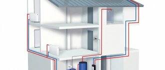
If the Tichelman system is installed on several floors, installation of a vertical riser is required. The main supply pipe follows to the highest point, from where a branch is made to supply the upper floor. After this, the main turns downwards, and in this section the supply is inserted for all lower floors. The common return current pipeline is made by analogy with a two-pipe system with counter-movement of the coolant, that is, it simply acts as a collection line.
The diameter of the pipes for the Tichelman loop is calculated using general methods of thermal engineering calculations, based on the selection of the optimal Kvs value of the main pipes. In this case, it is desirable that as the coolant moves, there is no stepwise reduction in the nominal flow rate, otherwise the natural balancing of the system will not be as good. In systems with a length of distribution pipelines of up to 120 m, the optimal nominal diameter of the main pipes is at least 270 mm2, and for radiator connection pipes - about 130 mm2.
Radiator fittings
You can often come across the opinion that a two-pipe heating system with a parallel movement of coolant does not require radiators to be equipped with control valves. It is believed that this fact allegedly neutralizes the additional costs of additional pipes and fittings for them. However, correct operation of radiators in this case is hardly possible.
Thermostatic heads for radiators in the Tichelman system must be installed. Without them, there is no way to individually configure radiators in different rooms, which is not very comfortable under changing climatic conditions. As for balancing valves (throttles), the debate is especially heated on this subject. As mentioned above, even with the parallel movement of the coolant, there is a pressure drop across the radiators. With proper calculation of the system, this phenomenon can be compensated for by varying the number of sections in the radiators of different zones. However, if there is even a minimal risk of error, it is better to install control valves on at least the first few radiators at each end.
The Tichelmann loop can also be balanced using static adjustment methods. We are talking about the so-called “washing”. If the coefficients of local resistance are predetermined by hydraulic calculations, the control valves can be replaced with inserts that lower the nominal diameter by a certain amount. Among the simplest options, we can offer self-made ring seals with different internal diameters, which are installed in the threaded connection points of radiators.
Two-pipe associated heating system - Calculation - Tichelman loop
If a Tichelmann loop heating system is used for a two-story house with an increased capacity pump integrated into the system, care must be taken to eliminate noise when the pump operates. Tichelman's scheme is quite simple.
In a classic two-pipe scheme, the return heating line starts from the last radiator and ends with the boiler, and the supply starts from the boiler and ends with the last radiator. It turns out that the first radiator from the boiler is the first on the supply and the last on the return, respectively, the last radiator is the last on the supply, but the first on the return.
This is a kind of direct-flow system in which the coolant in the supply and return heating mains moves in the same direction. First of all, we note the balance of the system and the absence of the need to install various adjustment equipment, which is quite expensive. At the same time, the coolant flow throughout the entire system is the same, and the operation of the heat-generating equipment is optimal and characterized by high efficiency.
The disadvantages of Tichelman’s scheme include the need to use additional pipes and preferably large diameter ones, which means additional costs. Moreover, the architectural features of a private house do not always allow the installation of an open heating system with three pipes.
For example, the installation of a heating system of this type may be hampered by doorways and a number of other architectural forms. Therefore, it is not always possible to organize a circular movement of the intermediate coolant in a two-pipe heating system of a private house.
We also note that in most cases, when installing reversible return heating systems according to the Tichelman scheme, horizontal wiring is used. In terms of other characteristics and the heating equipment and heat generators used, the Tichelman loop does not differ from its two-pipe analogues.
Heating systems in which the coolant is transported through a two-pipe passing circuit are called the Tichelman loop. The main features of the schemes are the absence of balancing work and operational stability. Let's consider the technical indicators, the design of the thermal main, the possibility of application and formation with your own hands. You should understand the advantages and disadvantages of the heating scheme and calculate the costs before choosing a connection of this type for private mansions.
You are misleading those who are trying to find the correct answers on heating systems on your website. The presented diagram of a Tichelman loop, by definition, is not one. The main advantage of the Tichelman loop is that the lengths of the direct and return sections for all radiators of the circuit must be the same relative to the boiler and pump, which guarantees equal hydraulic conditions for all radiators. This is NOT in your scheme.
Returning a return line with a large diameter in the backward direction, that is, actually laying three pipes, is not profitable. In small houses, it is generally easier and more profitable to lay pipelines along the walls in a dead-end pattern. Modern projects provide special solutions.... In the modern design of private houses, it is not uncommon to find additional doors to the terrace, to the garden, to unheated rooms, as well as high windows reaching to the floor.
Hanging pipes on walls is considered unacceptable and an element of the interior that does not correspond to modern ideas.
Factors of expediency of choice
Modern heating systems are presented in both the domestic and global construction industry markets in a wide variety. However, each of the proposed design solutions is advisable to apply in some specific cases. If we consider specifically the Tichelman loop system, its installation is a rational decision if:
Above is the traditional minimum list of conditions, according to which the choice in favor of a “ride” is rational and justified. Thus, if the operation of a circular pump is determined by the influence of balancing, and there is no need to lay a three-pipe system with large loops, it is the associated circuit that will function optimally in your home.
Valve setting - diagram with dead-end coolant movement
Hydraulics data
The operation of the system, based on the Tichelman loop principle, is highly stable. This fact is clearly demonstrated by hydraulic calculation data, however, this requires compliance with a number of installation rules.
The main functional element of such a system remains the hydraulic pump. It creates pressure at the outlet, that is, at the supply, and a vacuum at the inlet, the return. Numerically, the magnitude of both values decreases with distance from the pump, and the pressure drop does not occur linearly, it is described by the quadratic value of the dynamic pressure. This pattern can be traced for both the supply branch and the return branch; the fall can be conventionally described using the example of a 100 m long pipeline:
| Distance from the pump in the direction of coolant movement (m) | Supply pressure (% of nominal) | Return vacuum (% of nominal) | Radiator pressure drop |
| 10 | 90 % | 5 % | 95 % |
| 20 | 75 % | 20 % | 95 % |
| 30 | 55 % | 35 % | 90 % |
| 50 | 45 % | 40 % | 85% |
| 60 | 40 % | 45 % | 85 % |
| 70 | 35 % | 55 % | 90 % |
| 80 | 20 % | 75 % | 95 % |
| 90 | 5 % | 90 % | 95 % |
These are averaged data, but even from them it is clear that, despite the apparent uniformity, the pressure loss in the middle of the radiator network is slightly higher than at the edges. Indeed, due to the proportional change in pressure and vacuum in each radiator, an almost identical pressure drop is maintained in each heating device, however, for the correct and stable operation of the Tichelman loop, a number of rules must be followed, which will be discussed further.
Technology for installing a Tichelman loop in a private home
The rules for forming a Tichelman heating scheme for a two-story house are simple:
- the main structural element is a hydraulic pump;
- a common heating riser is formed;
- each floor has its own loop;
- the diameter of pipes and batteries is selected separately for each floor;
- Install a balancing valve into the hitch circuit - on each individual floor.
Boiler piping
There is a distinction between open and closed two-pipe networks with associated coolant circulation. Since more than 10 radiators are connected, it is impossible to push the shoulder through gravitational forces, therefore a safety system consisting of an automatic air vent, a bleed valve and a water meter is installed at the outlet through the supply pipeline.
Scheme of a single-pipe heating system for a private house
The following are cut into the return circulation line:
- circulation pump, the power of which is determined in accordance with the hydraulic resistance of the network;
- a mesh dirt filter is integrated in front of the pump;
- after the pumping equipment, a tee is inserted to connect the expansion tank and the lower point pressure gauge;
- a drain or filling pipe is cut into the installation area of the safety group.
Pipeline piping
PPR pipes are selected for the upper and lower distribution. If the installation is hidden, a PEX pipeline with push-on fittings is purchased. If pipes are laid in dense foundations, a thermal insulation shell must be used.
Selection of pipeline cross-section:
- The heat loss of a house of 150 m2 is no more than 15 kW - the cross-section of the internal tunnel is no more than 20 mm. Such pipes are used for internal mains of the network with batteries of up to 8 units. The pump is selected 25-40.
- The heat loss of a house with an area of 250 m2 is in the range of 15-27 kW - pipe cross-section up to 25 mm, pump 25-60.
Armature
In order for the Tichelman system to work properly in a two-story house, it is equipped with shut-off valves, which allow you to set the temperature in each room.
A statistical adjustment method using inserts instead of control valves will help balance the loop. Inserts reduce the nominal diameter by a specified amount. Install o-ring seals at the threaded connection point of the radiator. It is easy to make seals in the form of rings from a piece of dense rubber.
Boiler room piping
A two-pipe system with a parallel movement of coolant can be either open or closed. As we have already said, the main functioning element is the pump, so its installation cannot be avoided. You should not count on natural circulation even with properly organized upper pipe distribution. As we have already said, a typical Tichelman loop contains 10 or more radiators; it is unlikely to push through such an arm only by gravitational movement.
At the boiler supply outlet, a traditional safety “troika” is installed: an automatic air vent, a bleed valve and a pressure gauge. For open systems, the supply outlet must be organized in a vertical channel up to the height of the slope; an open expansion tank is installed at the highest point. Next, the supply pipe is sent directly to the distribution network.
One circulation pump is installed on the boiler return, the performance of which is determined by the hydraulic resistance of the entire system. Directly in front of the pump there is a strainer, and immediately after the pump there is a tee for connecting the expansion tank and a pressure gauge for the lower point. The filling pipe is also located in this place.
The shut-off valves of the boiler room are represented by full bore ball valves, which are installed:
- on both sides of the pump
- at the outlet of the expansion tank
- on the filling pipe
- at the points where the boiler is connected to the mains
Additionally, a connecting bypass tube can be installed in the boiler room, into the gap of which an electric normally closed valve is mounted, which is activated when the circulation stops. The bypass must be inserted before the circulation pump: the bypass is designed to protect against temperature shock and it bypasses the boiler heat exchanger from the main line, and not vice versa.
Installation
The installation process of the Tichelman heating system consists of the following steps:
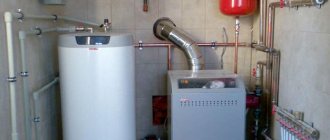
- First, the boiler is installed. In order to place it indoors, the minimum height from floor to ceiling must be 2.5 m, the permissible volume of the room is 8 m³. In order to find out the required power of the unit, you need to perform a calculation (examples can be found in specialized reference publications). To heat 10 m² you will need approximately 1 kW of power.
- The next stage is hanging the radiator sections. Initially, you need to determine how many radiators you need, then you need to mark their location (usually they are placed under window openings) and fasten them using special brackets.
- Next, we move on to the stage of stretching the line of the associated heating system. It is best to use metal-plastic pipes, which cope well with high temperatures and will also delight owners with a long service life and ease of installation. The main pipelines (supply and return) are from 20 to 26 mm and 16 mm for connecting radiators.
- Installation of a circulation pump. It should be installed on the return pipe as close to the boiler as possible. It needs to be inserted through a bypass with three taps. There must be a special filter in front of the pump. This requirement should not be neglected, since it has a direct impact on the service life of the equipment.
- Installation of an expansion tank and elements that are responsible for the safe operation of the equipment. For a heating system with a passing coolant movement, only membrane expansion tanks are suitable. Safety group elements are included with the boiler.
If you are planning to use the Tichelman scheme for a two-story house, then there is a special technology.
Pipe routing is carried out by tying the entire building, and not each floor separately. You should also install one circulation pump on each floor and leave unchanged the equal lengths of the return and supply pipelines for each radiator separately in accordance with the basic requirements of an associated two-pipe heating system. If you install one pump, then if it breaks down, the heating system in the entire house will become inactive.
Many experts consider it expedient to install a common riser on two floors with separate piping on each floor. In this way, you can take into account the difference in heat loss on each floor and select the required pipe diameters, as well as the required number of sections in the batteries.
A separate associated heating circuit on the floors will make setting up the system much easier, and will also allow for optimal balancing of the heating of the entire building. However, here you will need to embed a balancing valve into the hitch circuit for each floor. The taps can be placed one next to the other directly next to the boiler.
The popularity and widespread use of the Tichelman heating scheme is fully justified; many positive reviews from satisfied home owners using a similar scheme are direct confirmation.
Application area
However, the temptation to avoid hydraulically adjusting the system should not lead to hasty, thoughtless decisions. The two-pipe associated system is characterized by high material consumption, therefore its installation is not justified in all cases.
Let's consider such a concept as the degree of “pressure” of a heating device when balancing a two-pipe return system. By lowering the nominal diameter at the connection point of the first few radiators, it is possible to reduce the coolant flow in them, thereby reducing the pressure drop so that sufficient pressure is maintained in subsequent sections of the network. If the radiator network consists of a large number of heating devices located at a great distance from each other, the flow on the initial radiators will have to be limited to such an extent that the flow through them will not be enough for normal heat release. This forces the use of pumps with higher productivity, which is why noticeable noise is generated when the coolant flows in individual units. In general, we can say that the installation of a two-pipe associated system is justified only when the number of radiators is more than 8–10 and the total length of the pipeline is more than 70 m.
The material consumption of the Tichelman system increases significantly if it is impossible to wrap the radiator network into a ring, that is, to position the heating pipeline strictly along the perimeter of the building. This is usually hampered by doorways and floor glazing fronts. In such cases, it is necessary to install an additional pipe through which the coolant will return to the boiler room, and since the total length of an arbitrary loop increases by at least half, it is necessary to increase the nominal diameter of the line or the performance of the pump. In principle, additional costs can be avoided by installing a collector (radial) system, but it is better to first perform a comparative calculation of material consumption.
Algorithm for performing installation work
The installation of a two-pipe associated heating system is carried out in accordance with a certain algorithm, where the initial stage is the selection of pipe diameters, and the final stage is the installation of a circulator pump.
Calculation of pipeline diameter
There is a scientifically based method of calculation. The cross-section of the pipe is selected based on the volume of coolant passing through the pipe per unit time. The calculation starts from the distant radiator using the formula:
G=3600×Q/(c×Δt), (1)
where: G – water consumption for heating the house (kg/h);
Q is the thermal power required for heating (kW);
c – heat capacity of water (4.187 kJ/kg×°C);
Δt is the temperature difference between the hot and cold coolant, taken equal to 20 °C.
Next, calculate the cross-section of the pipes using the formula:
S=GV/(3600×v), (2)
where: S is the cross-sectional area of the pipe (m2);
GV – volumetric water flow (m3/h);
v is the speed of water movement, is in the range of 0.3−0.7 m/s.
The resulting figure is the cross-section; based on it, the internal diameter of the pipeline is selected.
This calculation is carried out for all radiators up to the boiler.
When calculating, you can also rely on the table of the dependence of the internal diameter of the pipe on the thermal load.
Table of dependence of the internal diameter of the pipe on the thermal load
The following guidelines can be taken into account:
- For heat losses of up to 15 kW (150 sq. m.) of area, pipes with a diameter of 20 mm are suitable.
- For losses from 15 to 27 kW (up to 250 square meters), pipes with a diameter of at least 25 mm will be required.
Carrying out calculations using the given formulas or hydraulic tables is a difficult task for the homeowner, so you can rely on the recommended pipe diameters.
The diameter of the pipeline must be the same throughout its entire length to ensure stable operation of the batteries. The recommended minimum internal diameter of pipes is 20 mm.
The following conditions must be met:
- Place pipes under the floor covering to avoid high-rise contours. If this is not possible, then you need to take into account the configuration of the house and strive as much as possible for the same height of pipe laying.
- Pipe material is metal-plastic or polypropylene reinforced with aluminum foil. Such pipes are stronger and will last a long time.
- Radiators are installed bimetallic or steel with a bottom connection system. Such batteries have higher hydraulic resistance, which balances the system. The power of the radiators should be the same throughout the entire area of the house.
- Each battery is equipped with a balancing valve on the return line. It is advisable to install thermostats.
Boiler installation
The room where the boiler is installed must have a height of at least 2.5 m. The volume of the room is recommended from 8 cubic meters. The hot water boiler must be selected depending on the area of the heated house. Boiler power for heating is 10 kW. m is equal to 1 kW. Based on this, the power for the entire system is selected.
The boiler piping consists of a set of shut-off valves; it is installed in several places:
- On the make-up pipe.
- On both sides of the pump.
- At the expansion tank.
- On the pipes coming from the boiler.
Mainline pulling
When installing the associated heating system distribution line, the following must be taken into account:
- The outlet branch of the main line must be located below the supply branch.
- The heat supply and heat removal pipes must be parallel to each other.
- The expansion tank must be installed above the heating boiler.
- Valves for draining water must be installed on the connecting radiators. It is recommended to install a thermostatic head on each radiator to ensure a comfortable temperature.
- When laying the pipeline, right angles are excluded to avoid the occurrence of air locks in the system.
- The expansion tank must be installed in a heated room.
- All diameters of pipes, fittings and taps must match each other. You cannot install pipes of different diameters in an attempt to save money. The water pressure in the system will be disrupted.
Installing a circulation pump
It is unreasonable to rely on natural circulation, since there are 10 or more batteries in the associated heating system. Gravity will not be able to work without forced pressure. The circulation pump is installed on the return branch near the boiler. The pump is installed using a bypass and three valves. It is recommended to install a filter.
A circulation pump is installed on each floor
The associated heating system is installed in one-story and two-story buildings. In two-story buildings, during installation you need to take into account some nuances:
- A circulation pump is installed on each floor. If a breakdown occurs on one floor, the heating will work fully on the other.
- For each floor it is recommended to install according to a separate scheme.
How does a dead-end heating system work?
A dead-end circuit is a two-pipe space heating device in which, as can be seen from the figure above, the hot coolant is supplied to each radiator through one pipe (supply), and leaves the radiators and goes to the boiler through another pipe (return). Moreover, in this scheme, the movement of the coolant through the supply and return pipes occurs in the opposite direction, while in other (not single-pipe) schemes the liquid moves in one direction. This is a very common option for connecting heating devices, and not only radiators - these can be cast iron or bimetallic batteries, or homemade registers.
Although single-pipe heating can be implemented using a dead-end scheme, this solution is unpopular due to its low heat transfer efficiency and complexity of implementation. The implementation of a dead-end single-pipe scheme is shown below - if the house is designed for 2 or three floors, then, in addition to the standard safety group, you will have to install risers and install an air vent or Mayevsky valve on each radiator. This is an expensive scheme, so it is not often accepted for execution.
An indirect advantage of the dead-end circuit is that it can be used both for heating with forced circulation of coolant, and for solutions with gravitational movement of liquid in pipes. For energy-independent heating of a private house, a system with natural circulation is becoming increasingly popular, so do not forget about the dead-end scheme with top pipe routing in this case.
In any case, with a single-circuit or double-circuit scheme, the following is obvious for the dead-end option: the more radiators connected to the pipe, the slower all subsequent heating devices will warm up. Therefore, it is advisable to divide the entire system into several branches so that each branch has no more than 5-6 radiators. This solution is relevant for both natural and forced coolant movement schemes.
In practice, the advantage of a dead-end scheme is obvious: simple calculations, a simple level of installation, a minimum number of shut-off valves and fittings, and the low cost of the entire project. If we compare with such popular solutions as a two-pipe system with a parallel movement of liquid and with a beam circuit (with a collector), then in terms of compliance with the laws of hydraulics, they are clearly better than a dead-end system - the coolant moves faster, there is no oncoming movement, the radiators warm up evenly and at the same speed. But often it is the efficiency of the dead-end option that wins, especially for heating a house with a small total heated area.
The horizontal scheme with dead-end wiring has a variation where a central highway is used. This scheme can be implemented as a pipeline hidden in the floor or wall, which appeals to all homeowners without exception, since a hidden pipeline does not require redesign, remodeling or changing the interior of the premises.
When installing a hidden pipeline, for example, when embedding pipes in a concrete floor screed or in grooves in walls, pipes should not be steel, but metal-plastic without joints or polymer with a connection using a fixed sleeve or welding to prevent the possibility of leakage. The only problem when laying a hidden pipeline is its correct and beautiful exit from the wall or from under the floor. You should also avoid any intersections of pipes in a hidden installation option. To avoid intersections, use a cross. When connecting a pipe to a radiator using a crosspiece, you can bend the pipes of the central line without protruding beyond the installation plane.
Also, the implementation of a dead-end system with a central mainline opens up the possibility of connecting other schemes to heating: a “warm floor” system or heated towel rails. Such units are connected using a special mixing module, which includes a circulation pump, mixing taps and temperature sensors. The mixing module makes the operation of the connected modules independent of the main heating circuit, and any number of new connected circuits will not affect the operation of the main circuit.
Advantages and disadvantages
The disadvantage is the need to lay pipes in a screed due to the presence of barriers around the perimeter of the room.
The advantages of installations of this type include uniform heating of the entire network and the ability to regulate heat transfer by radiators. The circuit is reliable; failures rarely occur in it, especially when compared with the operation of other systems with a large number of heating elements. This makes it a good option for use in a private home.
The main disadvantage of the design is the limitations associated with the internal features of the premises. The scheme involves walking around the perimeter of the building and returning to the boiler. In many buildings it is not easy to organize this - doors, flights of stairs and other obstacles prevent it. Also, installing thick pipes involves increasing the cost of the configuration.
Gravity option
Gravity heating scheme. Click on photo to enlarge.
It is the simplest and most primitive. Consequently, such a system is cheap and not too difficult to implement, since it depends on the layout of the home. But this is where its disadvantages lie. It is a large metal pipe connected to the boiler and passing throughout the house (this is a prerequisite), through which the coolant flows.
The disadvantage of this scheme is the need for massive pipes with a large cross-section in diameter, since installing thinner ones or adding batteries to the system leads to a decrease in heating efficiency due to a decrease in the water flow rate. In order to increase the efficiency of this heating system, not one, but two pipes are installed in the house, which causes even greater inconvenience to the residents.
What it is
In order to understand the features of this loop and understand the principle of its operation, it is necessary first to imagine the heating system itself, which is characterized by the associated movement of the coolant. In other words, the batteries in such a system are connected in series according to a predetermined pattern. That is why the occurrence of any failures and problems in the operation of the device is completely excluded.
Several pipelines depart from this unit, which are needed not only for the movement of coolant, but also for the outflow of water. There are several devices in the circuit, each of which is a shunt that plays an important role in the process of increasing hydraulic pressure in the system.
Unique design features make this option an excellent solution for a private home, since the resulting system boasts stable operation and uniform heating of each radiator.