I welcome you, friends, to the pages of the site!
RCD for lighting - to install or not? The relevance of this issue is confirmed by the many comments on my video channel on YouTube, as well as by the many questions received in the site’s feedback.
Let's look at this issue in detail and give specific recommendations.
Regulatory documents do not strictly regulate the installation of residual current devices on lighting lines. Let's consider both options.
Purpose and principle of operation
Three-phase residual current device (RCD)
A 3-phase RCD is designed to equalize the current that passes through the phase and neutral wires. In the absence of emergency situations, the indicated values are equal. Stable operation of electrical devices is possible because counter currents in the windings compensate each other. In the event of emergency situations, the protection device turns off the power to electrical appliances. This is observed when the insulation of wires is broken, which provokes the leakage of charged particles. As a result, the currents passing through the neutral and phase wires will have different values.
In every home, a situation can occur when an electric current penetrates the body of a washing machine or water heater. When the potential begins to flow to the floor, the 3-phase RCD will react and turn off the power to the devices. Therefore, when using this circuit breaker, you can be confident in your safety.
Connecting an RCD is relevant for powerful electrical appliances in the kitchen and bathroom. Condensation collects on their metal body, which together forms a potential conductor of electricity.
It’s good when protective shutdown is present on sockets, lamps and low-power household appliances. In the event of emergency situations, these consumers pose no less danger to humans.
Machine denomination
Table of ratings of circuit breakers
On the body of any device, the rated value is indicated - the value of the maximum continuous current that passes through the device without harm. This parameter is safe for current switching.
To ensure protection of the RCD itself, it is necessary to install a circuit breaker with a rating similar to or 1 more than the rating of the device. If you have a machine with a rating of 16 A, the RCD should be about 25 A. This current reserve will be enough to prevent the flow of energy when the load increases.
Device diagram
First of all, let us present a schematic diagram of the device, indicating its main elements.
RCD diagram
Designation:
- A – Relay that controls the contact group.
- B – Differential CT (current transformer).
- C – Phase winding on the DTT.
- D – Zero winding on the DTT.
- E – Contact group.
- F – Load resistance.
- G – Button that starts testing the device.
- 1 – Phase input.
- 2 – Phase output.
- N – Neutral wire contacts.
Where is the fire protection RCD installed?
Fire protection RCDs are installed in apartment electrical panels after the meter, in floor switchboards or in house input panels. They can also be located in the switchgear of a step-down transformer substation.
The main purpose of these devices is as follows:
- protection of the cable connecting the metering panel and the residential building.
- protection of electrical wiring sections where there is no RCD;
- switching off electrical panels when there is a short circuit inside the panel;
- duplication of downstream differential protection.
To ensure selectivity, the upstream fire protection RCD should be selected with a setting 3 times higher than that of the downstream one. For example, a protective device for a separate line must have an operating current of 30 mA, a device in the apartment panel is selected with a setting of 100 mA, protection on the floor is selected with a shutdown current of 300 mA, and a common house device must have a setting of 500 mA.
In addition, the response time must be taken into account. It should also differ by 3 times. The fastest-acting device is selected for individual lines and electrical appliances, otherwise, with large leakage currents, it is possible to turn off all protective devices at once - from those connected to a separate electrical appliance to a common one.
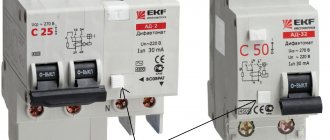
Marking
The marking is applied to the front panel of the device; we will tell you what it means using the example of a two-pole device.
RCD marking
Designations:
- A – Abbreviation or manufacturer’s logo.
- B – series designation.
- C – The value of the rated voltage.
- D – Rated current parameter.
- E – The value of the shutdown current.
- F – Graphic designation of the type of disconnecting current, can be duplicated with letters (in our case, a sinusoid is shown, which indicates the type of AC).
- G – Graphic designation of the device on circuit diagrams.
- N – Value of conditional short-circuit current.
- I – Device diagram.
- J – Minimum operating temperature (in our case: – 25°C).
We have provided standard markings that are used in most devices of this class.
Principle of operation
To understand how the protective structure performs its safety functions, you need to understand the operating principle of the RCD and the connection diagram. It has been established that the current from the network passes through the phase conductor through the load and then returns through the neutral wire. The operation of the device is based on this pattern.
Important! The operating principle of the RCD is based on comparing the values of the electric current at the output and input of the object, which is protected.
If Iin = Iout, then the device does not respond. As soon as Iin > Iout, the protective structure senses the leak and reacts as a result.
In other words, the currents passing through the phase and neutral wires must be the same (for a single-phase network). When the network is three-phase, then the value in the neutral is equal to the sum of the electric currents flowing in the phases. The inequality of electric currents indicates a leak, to which the device reacts.
When does an RCD not help?
However, you should not consider the RCD a panacea for any problems with electricity. The device is not smart enough to understand what exactly is included in the electrical circuit - a light bulb or a person. Shutdown will only occur if there is a leak.
The RCD does not protect against overvoltage, incl. from pulsed, as well as from low voltage, which “kills” electric motors - in a refrigerator, washing machine, and so on.
The unit also does not protect against short circuits. This task is performed by a circuit breaker or differential circuit breaker.
How many RCDs need to be installed?
To determine the exact number of RCDs required for a particular room, you will need a specialist who can carry out the appropriate calculations. For example, in a 1-room apartment, most likely, one such device, designed for a leakage current of 30 mA, will be enough. But in an apartment with four rooms and 15 groups of sockets, you will need at least five RCDs, as well as one device for the entire lighting group, electric stove and water heater.
It is usually assumed that one group of electrical appliances consists of one 30 mA residual current device plus one 100 or 300 mA fire protection RCD.
NOTE! To control the electrical wiring as a whole, it is recommended to install one general RCD with a rated breaking current of 300 mA at the entrance to a private house in addition to the calculated ones.
When is it not practical to install an RCD?
Sometimes there is simply no point in installing a device. One such situation is the presence of old and decrepit wiring. The ability of an RCD to detect a leak can become a headache if the device begins to operate unpredictably (which is what happens with poor wiring). In this case, the best solution would be to install the RCD not in the power supply circuit of the apartment as a whole, but in places with increased danger for using sockets.
There is also no point in buying a low-quality RCD. On the modern market you can find not only original devices, but also a wide range of fakes of unknown origin. Many of these devices are made “on the knee around the corner.” The use of such devices is completely unacceptable and inappropriate. Before purchasing, carefully study the technical documentation and quality certificates of the purchased unit.
It makes no sense to install the device in lines that supply voltage to stationary equipment and lamps, as well as in general electrical networks.
Uzo for lighting - should I install it or not? — LLC "UK Energotekhservice"
In order to protect the electrical network of a house or apartment, circuit breakers or fuses are used.
These elements allow you to avoid fire during a short circuit, but are completely unable to protect against electric shock.
A product for protective shutdown of electricity, the operating principle of which is aimed at preventing current leakage to the device body, allows you to instantly de-energize the entire home network if the phase current is outside the “permitted” section of the conductor.
The use of RCDs allows you to protect not only the home electrical network, but also powerful three-phase installations in production. Why to install such electrical products and how to do it correctly will be described in detail below.
Uzo for lighting - arguments for and against
Modern electrical wiring is divided into two groups: sockets and lighting. It is mandatory to install an RCD on the line of sockets; this requirement is also specified in the regulatory documents. But with lighting lines, not everything is so simple. Many electricians argue about whether to install an RCD for lighting.
Friends, I am glad to welcome you to the website “Electrician in the House”! In today’s article we will look at an example of some contradiction in the use of RCDs for lighting, when the rules actually say “NOT REQUIRED”, but according to the logic of common sense it should be installed. Should I install an RCD for lighting?
Should I install an RCD for lighting?
Electrical installations in residential and industrial premises require strict adherence to the rules approved by regulatory documents.
A professional electrician involved in the installation of electrical wiring and electrical equipment strictly follows the instructions specified in the technical documentation. This often leads to deterioration of the interior of the premises.
But the electrician will not change his decision for the sake of design, guided by the fact that in this case compliance with safety measures is more important.
List of main characteristics
Having understood the design of the devices and their operating principles, let’s move on to the main parameters. These include:
- The type of electrical wiring being protected, it can be single-phase or three-phase. This parameter affects the number of poles (2 or 4).
- The rated voltage is 220-240 Volts for two-pole devices, 380-400 Volts for four-pole devices.
- The value of the rated current load, this parameter corresponds to that of circuit breakers (hereinafter referred to as AB), but has a slightly different purpose (will be discussed in detail below), measured in Amperes.
- Rated value of differential (breaking) current, typical values: 10, 30, 100 and 300 mA.
- Type of disconnecting current, accepted designations:
- AC – Corresponds to sinusoidal alternating current. Both its slow increase and sudden manifestation are allowed.
- A – To the previous characteristics (AC), the ability to monitor the leakage of rectified pulsating current is added.
- S – Designation of selective devices; they are characterized by a relatively high response delay.
- G – Corresponds to the previous type (S), but with less delay.
Now it is necessary to explain the meaning of the rated current parameter, since it raises some questions. This value indicates the maximum permissible current for this electromechanical protective device.
When selecting this parameter, it is necessary to take into account that it should be one step higher than that of AB on a given line. For example, if the AV is designed for 25 A, then it is necessary to install protective devices with a rated current of 32 A.
Please note that this type of device is not intended to be triggered by short circuits and overloads. If such an accident occurs, all the wiring will burn out and a fire will break out, but the device will remain turned on. That is why such protective devices must be used in conjunction with AV. As an option, you can install a differential circuit breaker, which is essentially also a residual current device, but equipped with a short-circuit and overload protection mechanism.
SELECTION OF THE NUMBER OF AUTOMATICS BY RCD differential leakage current
The most important characteristic that influences the choice of the number of circuit breakers is the differential leakage current.
According to PUE 7 (electrical installation rules), its safe value for humans is 30 mA, accordingly the RCCB must be designed for this. PUE 7.1.79:
In an electrical panel, you cannot install a group line differential current switch with a rating of more than 30 mA. But connecting several group machines to it is allowed.
What prevents you from connecting as many AVs as you want to such an RCD is that even in a fully operational power supply system there are leaks, and if several groups are connected at once, they add up. It may turn out that the total value of all leaks from serviceable consumers will cause the RCCB to shut down.
You can find out the amount of group leakage in two ways:
1. Measure the actual value (use a milliammeter or variable resistor)
2. Calculate the value theoretically (in PUE 7 it is calculated at the rate of 0.4 mA per 1 A load and 10 μA per 1 m of conductor length.)
According to clause PUE 7.1.83:
More often, a calculation is made; it is not more accurate than measurements, but it allows you to select the correct number of machines for the RCD at the design stage. Below is an example of such a calculation:
If you connect 3 circuit breakers of 16 amperes each to the RCD, without knowing in advance what equipment will ever be connected to these lines, for calculation, the maximum possible group current is added up:
16A x 3pcs = 48A,
the resulting load is multiplied by 0.4 mA:
48A x 0.4mA=19.2mA
Next, the footage of the cable used for electrical wiring is calculated according to the plan of the apartment or house for all branches, let’s say it turns out to be 200 meters, multiply by 10 μA:
200m x 10 µA=2000 µA=2mA
Adding up the values, we get the total leakage of the three socket groups:
19.2+2=21.2 mA
As you can see, the resulting calculated differential current is less than the operating threshold of 30 mA and, it would seem, such a circuit can be safely implemented. It doesn’t even hurt to add another circuit breaker, but this is only in theory. After all, the same paragraph 7.1.83 of the PUE says that the maximum leakage of the system should not exceed the rated differential current of the RCD by more than one third (1/3), which is equal to 10 mA.
If you follow this rule, even two 16 Ampere circuit breakers used in apartment electrical systems cannot be connected to one RCD. The maximum, according to calculations, is that a load of no more than 22-25A is allowed at the same time, for example, two lighting groups (10A for each protection device).
This is, if you follow the instructions of the PUE, but in practice people, at their own peril and risk, modify this formula. For example, they use the demand factor for electrical equipment and take into account not the rating of circuit breakers in the formula, but the calculated energy consumption indicators of each group.
The logic here is as follows: it is unlikely that you simultaneously use all the electrical appliances in the house, mainly some of them, and accordingly, less than 16A is consumed. The average demand coefficient for an apartment is in the range of 0.5-0.8. Taking the lower value - 0.5, we get a load of not 48A, from three devices of 16A each, but 24A, which is freely calculated. Or the total calculated current of these groups is taken, and not the ratings of their circuit breakers.
Some do not adhere to the part where it is said that it is necessary not to exceed 1/3 of the rated differential current of the RCD, boldly raising this figure to 0.5 - 0.7 or greater, obtaining an indicator of permissible group losses, for example, 21mA, instead of 10mA.
Frankly speaking, in my practice I have come across many solutions based on these options and even a combination of them. Often, 1 or 2 RCDs were installed at the site, immediately behind the input circuit breaker, with a 30mA characteristic, and the owners did not complain about the outages.
Therefore, everyone must decide for themselves. If you want advice, then in my opinion, you can slightly exceed the leakage limit of 10mA (1/3 of the nominal value), especially in an apartment. But at the same time, it is better to leave free space in the electrical panel, in case you have to supply another Residual Disconnection Device.
Species and types
Modern manufacturers offer a variety of types and types of RCDs. The two most popular types of units in terms of their internal design on the electrical goods market are electromechanical (do not depend on current) and electronic (depend on). Selective and fire-fighting devices are also distinguished.
Electromechanical
Electromechanical RCDs are widely used and are used in AC electrical circuits. What causes this? The fact is that when a leak is detected, such a device will work, preventing dire consequences even at the smallest voltage.
This type of RCD in many countries is considered a standard of quality and one that is mandatory for widespread use. No wonder, because such an RCD will be operational even if there is no zero in the network and can save someone’s life.
Electronic
Such RCDs are easy to find on any construction market. The difference between them and electromechanical ones is that they are located inside the board with an amplifier, which requires power to operate.
However, such RCDs, as already mentioned, have a huge drawback - it is not a fact that they will operate in the event of a current leak (it all depends on the voltage in the network). If the zero burns out, but the phase remains, then the risk of electric shock does not go away.
NOTE! We are talking about the advantages and disadvantages of RCDs in general, and not specific models. If you are very lucky, you can become the owner of a low-quality RCD, both electromechanical and electronic.
Selective
The main difference between selective RCDs and their “brothers” is the presence in the circuit of a time delay function for turning off the circuit that powers the load, i.e. selectivity. Often this parameter does not exceed 40 ms. From this we conclude that selective devices are not suitable for protection against injury from direct contact.
Another feature of selective units is their good stability in response to current and voltage surges (the probability of false alarms is almost zero).
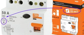
Fire protection
As the name suggests, such RCDs are used in the power supply systems of apartments and houses to prevent fires. However, they are not able to protect a person since the leakage current for which they are designed is 100 or 300 mA.
Typically, these units are installed in metering panels or in floor distribution boards. Their main task:
- input cable protection;
- protection of consumer lines in which differential protection is not installed;
- as an additional level of protection (if the device below it suddenly does not work).
Type of electromagnetic splitter (switch-off curve)
The next parameter by which the circuit breaker is selected is the type of electromagnetic splitter. It is responsible for the delay that occurs when triggered. It is necessary to avoid false shutdowns during the start of motors of various equipment.
When you turn on the motor of a refrigerator, dishwasher or washing machine, the current in the circuit increases briefly. This phenomenon is called inrush currents, and they can exceed operating consumption by 10-12 times, but they do not last long. Such a short-term increase does not cause harm. So, the electromagnetic splitter must have a delay that allows you to ignore these inrush currents. This characteristic is displayed in Latin letters B, C, D. This letter is placed before the rating of the circuit breaker (photo). Selecting a circuit breaker based on this criterion is not difficult. You just need to know the nature of the planned load:
- Category B circuit breakers turn off the power if the rated current is 3-5 times higher. Such machines can be used if high-power equipment with electric motors is not connected to the line. For example, for lighting, for socket groups into which low-power equipment is connected. They are also placed on dedicated lines, to which powerful household appliances are connected, but do not have motors - electric stoves, hobs, ovens.
- Category C packets will work if the current increases by 5-10 times. They withstand the start of the compressor of the refrigerator and freezer, as well as any other motors of household appliances.
- Class D protective circuit breakers will open their contacts if the current increases by 10-20 times. They are installed mainly in enterprises with powerful equipment. In the electrical wiring of a private house, it makes sense to install it only in a garage or workshop. If you are using any powerful devices there.
Actually, choosing a circuit breaker in this case is simple. On the lighting line it is enough to install category B machines; on the rest you can install C.
Is grounding necessary for an RCD?
Many homeowners believe that grounding for a protective device is mandatory, that it will only work normally if there is an electrical circuit that has a phase, a neutral and a ground (PE, yellow-green). Often homeowners ask another question: which is better - grounding or RCD. To answer it, you just need to compare the purpose of each protection.
The main function of a residual current device is to de-energize the network when a leakage current appears on the housing of a household appliance. This reaction helps prevent electric shock to a person. Grounding serves the same purpose, but its operation is different. If current appears on non-conductive parts, a short circuit occurs due to grounding. As a result, the machine’s protection is triggered and the equipment is de-energized.
Is RCD grounding necessary? It is desirable. Both methods can be used either separately or together, in combination. However, there is no need for grounding to use an RCD. The protection device is capable of operating in a single-phase two-wire network without a ground wire. The correctness of this conclusion can be verified by studying the RCD model. The device has 2 terminals - for phase and neutral, but there is no grounding contact.
For this reason, the device can be used in houses commissioned back in Soviet times. They did not have a grounding conductor, because the range of household appliances in stores was minimal. Such old apartments need an RCD. The difference between networks with and without grounding is only in the response speed. In the first case, the device responds almost instantly. In the second - only at the moment when the body of the device touches under voltage. Despite this drawback, serious electric shock can be avoided.
How does an RCD with grounding work?
The choice of protective device depends on the specific network configuration for which it is intended. The first thing you should always pay attention to is the presence or absence of a grounding conductor (PE). In modern houses it is provided for by the design. In old buildings, a PEN scheme is used, where the ground wire is combined with the neutral.
If there is a grounding in the circuit, then before installing the RCD it is necessary to accurately determine its type. In the TN circuit, solid grounding of the neutral conductor is used. TN-C differs in that one wire is intended for the neutral working and protective conductors. In this case, if the PEN conductor breaks, the entire potential may transfer to the body of the device, which has its own grounding.
Sometimes electricians resort to another incorrect scheme: they use a jumper that shorts the ground terminal of the socket and the neutral. In this case, an extremely dangerous situation can arise. If the PEN conductor breaks, the RCD will not work. The consequence will be electric shock to the person. However, there is an option that will allow you to avoid such a development of events. This is touching any ground loop: for example, elements of a water supply or heating system.
The safest scheme for connecting an RCD remains the TN-S scheme, where the protective wire is connected separately and combined with the neutral only in the power source. In this case, the probability of electric shock is reduced to zero even if the grounding or neutral conductor breaks. If both conductive elements are damaged, there is also no danger: the electricity will be completely turned off.
The TN-CS scheme is the last of the options; it is called intermediate. In it, the neutral and ground wires are combined only in separate sections. For such a circuit, the RCD becomes a mandatory part of the circuit. Otherwise, she will be left without protection.
Is an RCD effective without grounding?
After considering the question of how an RCD with grounding works, we need to focus on a diagram without it, since it is not provided for in old houses. In the event of a breakdown on the housing of a household appliance, the device will not immediately operate, since there is no main condition - leakage current due to the lack of grounding.
When a person touches the device, differential current will pass through the body. After some time, the triggering threshold will be reached, after which the current supply to the parting will stop. The severity of the damage depends on the installation of the protective device. Yes, turning off the power in this case will be quite fast. However, the risk of serious electrical injury cannot be ruled out. Therefore, without grounding it is impossible to guarantee the absolute safety of residents.
To protect people in houses with two-wire electrical networks, other devices must be included in the circuit. These are circuit breakers that will de-energize the network during short circuits or overloads. The best solution is difavtomats, which combine the functionality of an RCD and a simple machine. These devices will protect people from electric shock and protect wiring in the event of a short circuit.
General requirements. Electricity supply
7.1.13. Electrical receivers must be powered from a 380/220 V network with a TN-S or TN-CS grounding system.
When reconstructing residential and public buildings with a network voltage of 220/127 V or 3 x 220 V, the network should be switched to a voltage of 380/220 V with a TN-S or TN-CS grounding system.
7.1.14. External power supply to buildings must meet the requirements of Chapter 1.2.
7.1.15. In dormitories of various institutions, in schools and other educational institutions, etc. the construction of built-in and attached substations is not allowed.
In residential buildings, in exceptional cases, it is allowed to place built-in and attached substations using dry-type transformers in agreement with state supervisory authorities, while sanitary requirements for limiting noise and vibration levels must be fully met in accordance with current standards.
The construction and placement of built-in, attached and free-standing substations must be carried out in accordance with the requirements of the chapters of Section. 4.
7.1.16. It is recommended that power and lighting electrical receivers be powered from the same transformers.
7.1.17. The location and layout of transformer substations must provide for the possibility of round-the-clock unhindered access to them for personnel of the energy supply organization.
7.1.18. Power supply for safety lighting and evacuation lighting must be carried out in accordance with the requirements of Chapter. 6.1 and 6.2, as well as SNiP 23-05-95 “Natural and artificial lighting”.
7.1.19. If there are elevators in the building, which are also intended for transporting fire departments, their power supply must be provided in accordance with the requirements of Chapter. 7.4.
7.1.20. Electrical networks of buildings must be designed to power advertising lighting, shop windows, facades, illumination, outdoor, fire-fighting devices, dispatch systems, local television networks, light indicators of fire hydrants, safety signs, bell and other alarms, light fencing lights, etc., in in accordance with the design specifications.
7.1.21. When supplying single-phase consumers of buildings from a multiphase distribution network, it is allowed for different groups of single-phase consumers to have common N and PE conductors (five-wire network) laid directly from the ASU; combining N and PE conductors (four-wire network with PEN conductor) is not allowed.
When supplying single-phase consumers from a multiphase supply network with branches from overhead lines, when the PEN conductor of the overhead line is common to groups of single-phase consumers powered from different phases, it is recommended to provide protective shutdown of consumers when the voltage exceeds the permissible limit, arising due to load asymmetry when the PEN breaks conductor. The disconnection must be carried out at the entrance to the building, for example, by influencing the independent release of the input circuit breaker using a maximum voltage relay, and both the phase (L) and neutral working (N) conductors must be disconnected.
When choosing devices and devices installed at the input, preference, other things being equal, should be given to devices and devices that remain operational when the voltage exceeds the permissible voltage, arising due to load asymmetry when the PEN or N conductor breaks, while their switching and other performance specifications may not be met.
In all cases, it is prohibited to have switching contact and non-contact elements in PE and PEN conductor circuits.
Connections that can be disassembled with a tool are allowed, as well as connectors specially designed for this purpose.
Connecting an RCD in a two-phase network
Two-phase power refers to non-standard connections, where a converted old-style 127 V transformer was reconnected into a triangle for modern 220 V consumers, which are powered by linear voltage from it.
Rice. 4: Connecting an RCD in a two-phase system
To connect a residual current device to a two-phase circuit, it is necessary to disconnect both wires at the input to the panel, since each of them is under potential. Then each of the phases is connected to the corresponding phase terminals and neutral terminals, further observing their polarity. Unlike a single-phase system, circuit breakers at the output of the RCD must be installed for each line, or they can be replaced with one two-pole one.
Input devices, distribution boards, distribution points, group boards
7.1.22. A VU or ASU must be installed at the entrance to the building. One or more VU or ASU may be installed in a building.
If there are several economically separate consumers in a building, it is recommended that each of them install an independent VU or ASU.
The ASU is also allowed to supply power to consumers located in other buildings, provided that these consumers are functionally connected.
For branches from overhead lines with a rated current of up to 25 A, the VU or ASU may not be installed at the inputs to the building if the distance from the branch to the group panel, which in this case performs the functions of the VU, is no more than 3 m. This section of the network must be carried out with a flexible copper cable with with a conductor cross-section of at least 4 mm2, flame retardant, laid in a steel pipe, and the requirements for ensuring a reliable contact connection with the branch wires must be met.
For air input, surge suppressors must be installed.
7.1.23. Before entering buildings, it is not allowed to install additional cable boxes to separate the service scope of external supply networks and networks inside the building. Such separation must be carried out in the ASU or main switchboard.
7.1.24. VU, ASU, main switchboard must have protection devices on all inputs of supply lines and on all outgoing lines.
7.1.25. Control devices must be installed at the input of supply lines to the VU, ASU, and main switchboards. On outgoing lines, control devices can be installed either on each line, or be common to several lines.
A circuit breaker should be considered as a protection and control device.
7.1.26. Control devices, regardless of their presence at the beginning of the supply line, must be installed at the inputs of the supply lines in retail premises, utilities, administrative premises, etc., as well as in consumer premises that are administratively and economically isolated.
7.1.27. The floor panel must be installed at a distance of no more than 3 m along the length of the electrical wiring from the supply riser, taking into account the requirements of Chapter. 3.1.
7.1.28. VU, ASU, main switchboard, as a rule, should be installed in electrical switchboard rooms accessible only to maintenance personnel. In areas prone to flooding, they should be installed above the flood level.
VU, ASU, main switchboard can be located in rooms allocated in operational dry basements, provided that these rooms are accessible to maintenance personnel and are separated from other rooms by partitions with a fire resistance limit of at least 0.75 hours.
When placing VU, ASU, main switchboards, distribution points and group panels outside electrical switchboard rooms, they must be installed in places convenient and accessible for maintenance, in cabinets with an enclosure protection degree of at least IP31.
The distance from pipelines (water supply, heating, sewerage, internal drains), gas pipelines and gas meters to the installation site must be at least 1 m.
7.1.29. Electrical switchboard rooms, as well as VU, ASU, main switchboards, are not allowed to be located under toilets, bathrooms, showers, kitchens (except for apartment kitchens), sinks, washing and steam rooms of bathhouses and other rooms associated with wet technological processes, except in cases where Special measures have been taken for reliable waterproofing to prevent moisture from entering the premises where the switchgear is installed.
It is not recommended to lay pipelines (plumbing, heating) through electrical rooms.
Pipelines (plumbing, heating), ventilation and other ducts laid through electrical switchboard rooms should not have branches within the room (with the exception of a branch to the heating device of the switchboard room itself), as well as hatches, valves, flanges, valves, etc.
Laying gas and pipelines with flammable liquids, sewerage and internal drains through these premises is not permitted.
Doors to electrical rooms must open outward.
7.1.30. The premises in which ASUs and main switchboards are installed must have natural ventilation and electric lighting. The room temperature should not be lower than +5 oC.
7.1.31. Electrical circuits within the VU, ASU, main switchboard, distribution points, group panels should be made with wires with copper conductors.
Connecting an RCD in a three-phase network
Protection of devices powered by three phases at once is carried out according to a similar principle, with the difference that the RCD is selected for four outputs. An example of connection is shown in the figure below:
Rice. 5: Connecting an RCD in a three-phase system
As you can see, in this case, the protective device is also connected after the electric meter and the introductory packet. Individual circuit breakers that respond to phase short circuits are already connected behind it, and, if necessary, more sensitive RCDs are connected to create selective operation for certain groups of consumers.
Since installing a separate device for each phase is too expensive, group RCDs are used in three-phase circuits, which work with all elements of the line at once.
Fire protection RCD for a private home: how to choose and install correctly
A fragment of the connection diagram for a four-pole fire protection RCD at the entrance to a private house explains the main principle of its selection based on differential current.
It is placed at the entrance to the building for protection:
- input cable;
- lines to consumers where individual residual current devices are not used;
- acting as a reserve in case of failure of the main module.
The fire protection RCD is connected to the power supply circuit of the house with mandatory observance of the selectivity of its operation. This is achieved in a comprehensive manner by two settings:
- threefold reserve of the differential current setting in comparison with any group or individual module located below;
- delay in response time by at least 3 times.
A fragment of the above connection diagram shows that the differential current of the fire protection module IΔns is three times higher than the leakage setting IΔn1 or IΔn2 for any group of consumers.
Fire protection RCDs are designed to be triggered by leakage currents of 100, 300 or 500 mA, and human protection modules from differential current are manufactured with settings of 30, 10 or 6 milliamps.
The ability to set a time setting for selective operation is indicated on the module body with the Latin letter “S”.
The correct choice of settings for fire protection, group and individual RCDs for differential current and shutdown time of an emergency is an obligatory principle of reliable liquidation by protecting the damaged area while leaving serviceable equipment energized.
Connecting a three-phase RCD: 4-pole circuit without using a neutral
The case of using a symmetrical load, in which all currents in the phases are always equal, allows one to abandon the operation of the neutral wire and simplify the design.
An example of such a connection is the protection of a three-phase asynchronous electric motor. Its stator windings can be assembled in a star or delta configuration, which provide equal resistance between phases.
The working zero potential is connected to the input contact of a four-pole RCD, and nothing is connected to the output. The potential output terminal N remains empty.
This technique allows you to save money by connecting the motor to the power circuits with a cable with four rather than five cores: three for phase potentials and one for the protective PE conductor.
It is mounted on a special housing grounding bolt.
Connecting a three-phase RCD: 4-pole circuit using neutral
A simplified diagram for connecting a four-pole RCD to a three-phase network can be represented as follows: at the output of the working zero, a busbar is used to distribute neutral potentials N to connected consumers (circuit with neutral).
Consumers can be powered from all 3 phases or just one. The same circuit allows you to simultaneously protect three different single-phase circuits, provided that a common neutral is used.
At the same time, they try to arrange the operation of the equipment in compliance with the uniform distribution of load currents across all phases.
Connecting a three-phase RCD: diagram for a single-phase network
The proposed option is not typical.
It is used as an exception in three cases:
- The owner has an extra protection module that needs to be put into operation. Otherwise, it will simply gather dust without use.
- The assembled single-phase wiring is planned to be converted to three phases in the near future.
- Temporary replacement of a module that fails when an accident occurs.
In all three cases, it is necessary to pass the phase potential through those terminals to which the “Test” button winding is connected. Otherwise, it will not work during manual checks.
.
Mandatory installation according to PUE and GOST
RCDs for lighting at objects of various categories in accordance with the requirements of PUE and GOSTs must be installed:
- In particularly damp and fire hazardous areas, where they are used as reliable protection against leakage currents.
- If it is impossible to install lighting fixtures with a safe supply voltage of up to 40 Volts.
- When arranging networks based on luminaires and lamps, the lowest point of location of which is below 2.5 meters.
Additional information: In particularly humid rooms with a 220-volt mains supply, in addition to the RCD, a step-down transformer must be used.
To assess the safe location of household lighting, you should know that with ceilings in most apartments at a level of 2.5-2.7 meters, the elements of a chandelier placed on it will be below the permissible limit. In addition, according to current regulations, RCDs are installed in the power circuits of the following objects:
- In lighting systems used on signs and advertising.
- For decorative lighting of monuments.
- In crowded places (at public transport stops, near route signs, etc.).
- At outdoor lighting facilities.
When updating or repairing home electrical wiring, you should know that you need to install an RCD on the lighting circuit in the bathroom and toilet. For a private house, you will need to add a bathhouse or sauna to this list, as well as a veranda, swimming pool, attic and basement.
Checking the RCD
After switching all circuits, the intra-house network must be powered. If the circuit breakers or RCDs do not turn off, then there is no short circuit and the neutral conductor is not in contact with ground.
Next, press the “TEST” or “T” button located on the front panel of the device. In this way we forcefully simulate the occurrence of leakage current. A working RCD should immediately operate and de-energize the protected area. If this does not happen, then in the event of an emergency the device will not help cope with the problem.
The last stage of the test can be considered the supply of load to the RCD. It is necessary to turn on one by one all devices that will work in a specific circuit and the network as a whole. In case of possible problems, it is necessary to make changes to the protection circuit or change the ratings of residual current devices.
RCDs are not the only way to protect people from electric shock and network overloads, which can lead to fire. But often it is these devices that save lives and ensure the safety of citizens’ property.
What is fire protection based on?
A short circuit between live parts of electrical equipment and grounded parts of the structure causes a short circuit current that is sufficient to trip the circuit breaker.
However, if the insulation is damaged, a short circuit does not always occur. In some cases, a leakage current appears, the value of which is only 100-500mA.
At a voltage of 220V, the power released at the fault point reaches 100W. The flame of a pocket lighter has a similar power and is quite sufficient to heat the scene of an accident to the ignition temperature of nearby flammable materials. To protect against such situations, a fire protection RCD is used.
The setting of such a device, depending on the model, ranges from 100 to 500 mA. Such currents are dangerous to human health and life, but a fire protection RCD for a private home can protect electrical wiring from fire and the house from fire.
The design and operating principle of this device is no different from conventional devices, except for a higher leakage current . In RCDs and automatic devices used in home electrical wiring, it is 10-30mA. The rated current of fire protection devices can be anything, but usually it starts from 25A and depends on the relay installed inside the device.
| Information! The number of poles depends on the number of phases - two-pole devices are installed in a single-phase network, and four-pole devices are installed in a three-phase network. |
Basic mistakes when connecting an RCD
When connecting an RCD, many people make common mistakes that can have very serious consequences for a person. To avoid them, follow these rules:
- the input terminals of the residual current device must be connected only after the corresponding circuit breaker; direct connection to the network is unacceptable;
- observe the correspondence of neutral and phase contacts, their designation is specifically indicated on the housing;
- when installing wiring, carefully follow the diagram, especially for objects with branching, a large number of connected objects and several RCDs for them;
- if there is no grounding conductor in an apartment or house, then it should never be replaced with a wire thrown over heating radiators or water pipes; grounding must be made in accordance with the rules;
- pay attention to the performance characteristics of the purchased devices (rated operating current and shutdown current) and their compliance with the network parameters, for example, if a current of 50A can flow in the line, then the device should be selected at least 63A.
To protect yourself during connection, follow basic electrical safety rules.
In what cases can you not put
Taking into account the possible risks of an RCD for lighting, it is allowed not to install it in the following situations:
- when the lighting fixtures are at a sufficient height to prevent a person from touching their body;
- if the switch in the apartment is installed correctly (precisely in the “phase” break);
- provided that during repair or renovation of a chandelier, for example, the switch is always turned off.
In these situations, the danger of electric shock due to its leakage onto the chandelier body is minimal.
Proponents of this option refer to Chapter 7.1. PUE, which stipulates that installation of a protection device in lighting lines is not necessary. Extract from PUE clause 7.1.79:
Cases when the question arises: is an RCD needed for light, are listed below:
- The need to save space within the electrical panel.
- Reducing the cost of its installation.
- The desire to reduce the likelihood of triggering for false reasons.
However, if this reduces the level of electrical protection of a person, it is imperative to install an RCD on the light.
What are called difavtomats?
Differential automatic machines are, in fact, also a type of RCD. It just turns out that these are two devices in one, since the mechanism is capable of controlling both current leakage and voltage.
The differential machine consists of a switch and a machine
On the body of this device you can notice the presence of special markings that not only indicate the rated current, but also the maximum value that it can withstand. However, the mechanism will work at a lower rated current.
It turns out that this is an improved device that replaces the automatic machine and the standard version of the RCD. The difference is that such a mechanism has a higher cost.
Safety regulations
Options
When installing a difavtomat, three main parameters should be taken into account:
- Supply voltage and number of phases – 220V or 380V, 1 phase or 3.
- Operation current. This parameter is similar to that of the circuit breaker.
- Leakage current. Everything here is similar to an RCD.
There are a few more parameters that not everyone is familiar with:
- Rated breaking capacity. Short circuit current that the device can withstand without malfunctioning.
- Response time of differential protection.
- Current limiting class. Shows the time it takes to extinguish the electric arc during a short circuit.
- The type of electromagnetic release on which the excess of the operating current compared to the rated one depends.
Type of electromagnetic release
The electromagnetic release in the automatic circuit breaker is designed to instantly open the circuit when the rated current is exceeded by a specified number of times. The following types are common:
- B – the operating current exceeds the rated current by 3-5 times.
- C – operation current exceeds the rated current by 5-10 times.
- D – operation current exceeds the rated current by 10-20 times.
Leakage current (disconnecting differential current) and its class
The sensitivity threshold of the differential transformer determines the leakage current, which triggers the protection. The most widespread are differential transformers with a sensitivity of 10 and 30 mA.
In addition to the numerical value of the leakage current, the shape is important. In accordance with this, the following classes of protection devices are distinguished:
AC – sinusoidal leakage current is controlled. A - in addition to sinusoidal, a pulsating constant is taken into account, which is important when protecting digital electronic equipment. B – a smoothed constant is added to the listed currents. S – shutdown time delay – 200-300 ms. G – time delay – 60-80 ms.
Rated breaking capacity and current limiting class
This parameter characterizes the short circuit current that the contact group of the circuit breaker is able to withstand without damage during the shutdown time. The higher the value of the parameter, the greater the likelihood that after eliminating the damage in the network, the difavtomat will remain operational. A typical range of values is:
- 3000 A;
- 4500 A - together with the first value, is practically not used today;
- 6000 A is a frequently used value;
- 10000 A - suitable for places close to the power substation, but has a high cost.
The current limiting class characterizes the shutdown speed when a critical current flows. The switch-off time (speed) includes the arc extinguishing time between the breaking contacts. Less time, i.e. higher shutdown speed, guarantees greater safety. There are three classes: from first to third.
Electronic or electromechanical
Based on internal equipment, electromechanical and electronic devices are distinguished. Electromechanical automatic machines are considered more reliable and do not require external power to operate.
Electronic devices have more stable parameters, but for normal operation they require stable power at the input.
Selective type operating principle
In branched electrical networks, a two-level protection system is used.
At the first level, a differential automatic machine is installed that controls the load line completely. On the second, difavtomats control each selected circuit separately.
To prevent the simultaneous operation of protection devices of both levels, the first differential circuit breaker must have selectivity, which is determined by the shutdown delay time. For these purposes, machines of classes S or G are used.
How to properly connect wiring to machines
There are a large number of devices that will make it easier to connect contacts to automation. In order to choose the appropriate option, we will consider them in detail.
Flexible wire lugs
In order to connect elements of an electrical panel, flexible wires with many wires are often used, because even a beginner can cope with connecting such contacts. But there is a nuance here too.
As we have already discussed above, many craftsmen fix the wire with a clamp without termination, which is why the fragile wires begin to break off and the contact weakens.
If stranded wire is used during installation, then do not forget about the lugs
Sometimes it becomes necessary to fix two contacts at once into one clamp, so double tips were invented for this purpose. They are best suited when you have to install a lot of jumpers.
Special tip for forming bridges
Arched bend
Usually, to connect the conductors to the clamps, it is necessary to remove 10 millimeters of the insulating layer - this is enough to form an arc on the messenger, which is then placed in the terminal. As practice shows, most electricians, in the absence of tips, use this method.
As a result, it is possible to obtain reliable contact that will not weaken over time. This method is suitable if there is a monolithic core at the end.
Thanks to this connection, the area of interaction between the contact and the clamp expands, this will avoid problems with the operation of the machine
Unbreakable jumpers
When you have to connect several machines with one wire, it becomes necessary to use a comb (bus). However, it is not always at hand, so you can form a homemade comb from wire of any cross-section.
You should bend the wire so that you get a comb. Then, at the bend site, you need to strip the wires.
Method for forming a continuous comb
Where to install?
As a rule, the protective device is installed in an electrical panel, which is located on the landing or in the residents' apartment. It contains many devices that are responsible for metering and distributing electricity up to a thousand watts. Therefore, in one panel with an RCD there are machines, an electric meter, clamping blocks and other devices.
If you already have a shield installed, then installing the RCD will be easy. To do this, you will only need a minimal set of tools, which includes pliers, wire cutters, screwdrivers and a marker.
The process of installing automation in an electrical panel: step-by-step instructions
Let's consider the option of assembling an electrical panel for a one-room apartment; a switch, a protective multifunctional device will be used here, then a group of RCDs will be installed (type “A” for a washing machine and dishwasher, because such a device is recommended by the equipment manufacturer). After the protective device there will be all groups of circuit breakers (for air conditioning, refrigerator, washing machine, dishwasher, stove, and also for lighting). In addition, pulse relays will be used here; they are needed to control lighting devices. A special module for wiring will also be installed in the panel, which resembles a junction box.
Step 1: first, you need to place all the automation on the DIN rail, in the way we will connect it.
This is how the devices will be located in the panel
In the panel there is first a switch, then an UZM, four RCDs, a group of circuit breakers of 16 A, 20 A, 32 A. Next are 5 pulse relays, 3 lighting groups of 10 A and a module for connecting the wiring.
Step 2: Next we need a two-pole comb (to power the RCD). If the comb is longer than the number of RCDs (in our case, four), then it should be shortened using a special machine.
Cut the comb to the required size, and then install stops along the edges
Step 3: Now all RCDs should be fed together by installing a comb. Moreover, the screws of the first RCD should not be tightened. Next, you need to take cable sections of 10 square millimeters, remove the insulation from the ends, make crimping with lugs, and then connect the switch to the UZM, and the UZM to the first RCD.
This is what the connections will look like
Step 4: next you need to supply power to the switch, and accordingly to the UZM with the RCD. This can be done using a power cable, which has a plug at one end and two crimped wires with tips at the other. Moreover, you first need to insert the crimped wires into the switch, and only then make a connection to the network.
Next, all that remains is to connect the plug, then set the approximate range on the UZM and click on the “Test” button. So, you can check the functionality of the device.
Here you can see that the UZM is functioning, now you need to check each RCD (if connected correctly, it should turn off)
Step 5: Now you need to turn off the power and continue assembly - you should power the group of circuit breakers on the central rail with a comb. Here we will have 3 groups (the first is the hob/oven, the second is the dishwasher and washing machine, the third is the sockets).
We install the comb on the machines and transfer the slats to the panel
Step 6: Next you need to move on to the zero buses. There are four RCDs installed here, but only two zero buses are required, because they are not required for 2 groups. The reason for this is the presence of holes in the machines not only at the top, but also at the bottom, so we will connect the load to each of them, so a bus will not be required here.
In this case, you will need a cable of 6 square millimeters, which must be measured in place, stripped, clamped at the ends and connected to the RCD with its groups.
Using the same principle, it is necessary to power the devices with phase cables
Step 7: since we have already connected the automation, all that remains is to power the pulse relays. They should be connected to each other with a 1.5 square millimeter cable. In addition, the machine phase should be connected to the junction box.
This is what the assembled shield will look like
Next, you need to take a marker to mark the groups for which this or that equipment is intended. This is done in order to avoid confusion in case of further repairs.
Safety precautions when working with RCDs and automatic machines
Safety Basics
Work is carried out in compliance with the following rules:
- The line is de-energized and checked for absence of voltage with an indicator screwdriver. If the switch is located far from the installation site of the RCD, you should attach a sign on it with the text “People are working!” or place a watchman. To be safe, it is recommended to disconnect the wires from the terminals.
- When connecting wires, use only methods approved by the PUE: clamps, terminals, crimping with sleeves, welding. Soldering is not recommended; twisting is prohibited.
- The correct installation is checked by measuring the resistance of the phase-zero loop. A high indicator indicates poor contact in one of the connections. During operation, such places become hot and can cause a fire.
- Before applying voltage, protect eyes and exposed parts of the body. A low-quality product may fly apart.
- Do not use wires with insulation of the same color.
Sources
- https://StrojDvor.ru/elektrosnabzhenie/princip-raboty-i-sxema-podklyucheniya-uzo-v-trexfaznoj-seti/
- https://electrik-ufa.ru/raznoe/printsip-raboty-uzo-v-odnofaznoj-seti
- https://odinelectric.ru/equipment/circuit-breaker/chto-takoe-uzo-naznachenie-markirivka-vidy
- https://dom-i-remont.info/posts/elektrika/nadezhnaya-elektrozashhita-seti-kak-rabotaet-uzo-s-zazemleniem-ili-bez-nego/
- https://www.asutpp.ru/kak-pravilno-podklyuchit-uzo.html
- https://ElectrikBlog.ru/kak-podklyuchit-uzo-pravilno-instruktsiya-na-7-skhem-s-foto/
- https://zen.yandex.ru/media/rmnt/kak-vybrat-i-pravilno-podkliuchit-uzo-5bd9504cb098ea00a9cc3e8d
- https://altenergiya.ru/poleznye-stati/sxemy-podklyucheniya-uzo-v-odnofaznoj-i-trexfaznoj-seti-varianty-montazha-i-pravila-bezopasnosti.html
- https://stroyhelper.ru/shema-podklyucheniya-uzo/
Why is it needed?
Installation of such devices is necessary for several reasons. Mainly, it was designed for protection. From what? Firstly, the RCD protects people from electric shock, especially in cases where there are faults in the electrical installation. Secondly, the device is triggered and cuts off the current due to accidental or erroneous contact with live parts of the electrical installation, in case a current leak occurs. And thirdly, it prevents the electrical wiring from igniting in the event of a short circuit. As can be seen from the above, this machine actually performs a very important function.
RCD
Today you can find differential circuit breakers, the peculiarity of which is to combine a circuit breaker and an RCD. Their advantage is that they take up less space in the shield. In all cases, when connecting, all contact connections must be connected to it not from below, but only from above. One reason is that it is more aesthetically pleasing. But there is a much more compelling reason. The fact is that an RCD can reduce the efficiency of all household items. Moreover, during repair work, the electrician will not get confused, and he will not have to study complex, confusing diagrams. So now it's time to look at your connection options.