Purpose and scope of RCD
The RCD is designed to compare the amount of electric current flowing in the phase and neutral wires. During normal operation of electrical appliances, this value is the same and the counter currents in the RCD windings compensate each other. As soon as an emergency situation occurs - the insulation is broken somewhere with the subsequent flow of charged particles to the ground, bypassing zero, the differential currents will differ and the protection will turn off the power.
In practice, this can be represented as follows: if the electrical wiring breaks down on the body of a washing machine or water heater, their body will be at potential. As soon as the potential begins to flow from the body to the ground, the protection will react and the person will not be harmed. It is most important to connect an RCD to a circuit of powerful appliances in the kitchen or bathroom, because of the release of condensation on their surface and metal body, which is a potential conductor.
But this does not mean that other equipment does not require similar devices for protective shutdown: the same lamps, sockets and other connected loads can also pose a threat to humans. Therefore, it is also important to connect them to the RCD on the panel, both common for all electrical wiring, and separately for any devices or their groups. Features of the use of electronic and electromechanical RCDs directly depend on the power supply circuit and the location of their installation.
Selecting a protection device
Based on the above characteristics, an RCD is selected, but do not forget to take into account the conditions of the bathroom (high humidity).
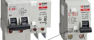
Give preference to type “A” devices, which respond to alternating and direct current. Despite the fact that sinusoidal alternating current flows in our electrical network, modern household appliances are equipped with special power supplies based on electronic semiconductor elements. Due to this, the AC sinusoid in the power supply is converted into a pulsed half-cycle. And if the leak is of this nature, then a cheaper “AC” type device will not react to it and will not work.
Carefully consider the passports for the washing machine and water heater when you are planning to buy an RCD.
It is for equipment installed in the bathroom that manufacturers indicate the type of device required, most often it is “A”.
Some differential circuit breakers have an additional block in their design, with the help of which consumers are disconnected in the event of a break in the neutral wire in the network.
For household appliances in bathrooms, it is recommended to install an RCD with a rated differential current of 10 mA. According to the time-current characteristic parameter, type “C” is preferable.
If you are not sure that you can choose a protective device yourself, then go shopping at retail chains that have a good reputation. Qualified sales consultants will provide you with the necessary assistance, tell you which manufacturer to choose, and select the appropriate device according to your financial capabilities.
Connection diagrams for RCDs in a single-phase network
Most household consumers are powered by a single-phase circuit, where one phase and neutral conductor is used to supply them with electricity.
Depending on the individual characteristics of the network, single-phase power supply can be provided according to the following scheme:
- with a solidly grounded neutral (TT), in which the fourth wire acts as a return line and is additionally grounded;
- with combined neutral and protective conductor (TN-C);
- with separated zero and protective grounding (TN-S or TN-CS; when connecting devices indoors, you will not find any difference between these systems).
It should be noted that in the TN-C system, in accordance with the requirements of clause 1.7.80 of the PUE, the use of differential circuit breakers is not allowed, except for the protection of individual devices with the obligatory combination of zero and ground from the device to the RCD. In any situation, when connecting an RCD, the characteristics of the supply network should be taken into account.
Without grounding
Since not all consumers can boast of having a third wire in their wiring, residents of such premises have to make do with what they have. The simplest circuit for connecting an RCD is to install a protective element after the input circuit breaker and the electric meter. After the RCD, it is important to connect circuit breakers for different loads with the corresponding shutdown current. Please note that the operating principle of RCDs does not provide for disconnecting current overloads and short circuits, so they must be installed together with circuit breakers.
Rice. 1: Connecting an RCD in a single-phase two-wire system
This option is relevant for apartments with a small number of connected devices. Since if there is a short circuit in any of them, shutting down will not bring any noticeable inconvenience, and finding the damage will not take much time.
But, in cases where a sufficiently branched power supply circuit is used, several RCDs with different operating current values can be used.
Rice. 2: connecting an RCD in a branched single-phase two-wire system
In this connection option, several protective elements are installed, which are selected according to the rated current and operation current. As general protection, an incoming 300 mA fire protection RCD is connected here, followed by a neutral and phase cable to the next 30 mA device, one for sockets, and the second for lighting; a pair of 10 mA units are installed for the bathroom and nursery. The lower the response rating is used, the more sensitive the protection will be - such RCDs will operate at a significantly lower leakage current, which is especially important for two-wire circuits. However, it is also not worth installing sensitive automation on all elements, since it has a high percentage of false positives.
With grounding
If there is a grounding conductor in a single-phase system, the use of an RCD is more appropriate. In such a scheme, connecting the protective wire to the device body creates a path for current leakage if the insulation of the wires is broken. Therefore, the protection will operate immediately in the event of damage, and not in the event of electric shock to a person.
Criterias of choice
Devices are selected according to their intended purpose:
- For sockets and electrical appliances - 10 and 30 mA.
- For lighting networks of wooden houses - fire protection (100, 300 and 500 mA).
When selecting an RCD based on sensitivity, you should keep in mind natural current leaks. In the network they are (mA):
- Iut=0.01*L, where L is the total length of wires, m;
- in the electrical receiver - Iut=0.4*L.
If the natural leakage is 150 mA, then a device of 100 (mA) or less will often falsely operate. Large networks are divided into groups.
The class of the device by the type of leakage current is chosen in accordance with the type of electrical receivers. It is irrational to install type A devices on all lines, since they are much more expensive than AC.
Devices are selected based on sensitivity.
Electromechanical RCDs are the most reliable. The amplification circuit in electronic analogues requires power. If the neutral above the device breaks, it is de-energized and the RCD becomes inoperable. At the same time, live parts remain energized, which means there is a risk of electric shock and fire.
It is recommended to purchase electronic models only as a last resort if there is little free space in the panel. For example, a voltage relay and a smart home system contactor are already installed on the DIN rail.
In terms of rated current, the device must be one step higher than the circuit breaker protecting it. It opens the circuit instantly only in the event of a short circuit, and at lower overloads the response time can reach 60 minutes. Throughout this period, a current higher than the rated current will flow through the RCD, which will lead to breakdown.
Connecting an RCD in a two-phase network
Two-phase power refers to non-standard connections, where a converted old-style 127 V transformer was reconnected into a triangle for modern 220 V consumers, which are powered by linear voltage from it.
Rice. 4: Connecting an RCD in a two-phase system
To connect a residual current device to a two-phase circuit, it is necessary to disconnect both wires at the input to the panel, since each of them is under potential. Then each of the phases is connected to the corresponding phase terminals and neutral terminals, further observing their polarity. Unlike a single-phase system, circuit breakers at the output of the RCD must be installed for each line, or they can be replaced with one two-pole one.
Selection of protective device
When choosing an RCD for a boiler, it is necessary to take into account its technical characteristics. The main ones include the following:
- Operating current. Determined by the power of the water heater.
- Differential current. Depends on operating current.
By working is meant the current passed through the power contacts of the protective device. It directly depends on the power of the water heater. For example, if the boiler power is 2.5 kW, then the operating current is 2500/220 = 11.4 A. It is advisable to select the RCD with a margin of operating current. In this case, a 16 A device is suitable.
The differential current (leakage) is determined from the operating current of the consumer. For a boiler with a power of 2.5 kW and a current consumption of 11.4 A, an RCD with a leakage current equal to 11.4 * 0.4 = 4.6 mA will be required. This figure is approximate. It is influenced by the length and condition of the electrical wiring. Therefore, in everyday life, residual current devices with a leakage current of 30 mA are usually installed.
Additional Information. Current leaks also exist in fully operational equipment and wires. However, their level is minimal and is about 10 μA. If the cables are old, then the leakage value increases many times. Therefore, RCDs are not recommended for use with old equipment or wiring.
Connecting an RCD in a three-phase network
Protection of devices powered by three phases at once is carried out according to a similar principle, with the difference that the RCD is selected for four outputs. An example of connection is shown in the figure below:
Rice. 5: Connecting an RCD in a three-phase system
As you can see, in this case, the protective device is also connected after the electric meter and the introductory packet. Individual circuit breakers that respond to phase short circuits are already connected behind it, and, if necessary, more sensitive RCDs are connected to create selective operation for certain groups of consumers.
Since installing a separate device for each phase is too expensive, group RCDs are used in three-phase circuits, which work with all elements of the line at once.
Manufacturers of protective devices
Most modern water heaters are equipped with a plug with an RCD. If assembly is poor or incorrectly connected, the protective device on the cable may fail. In such a situation, there is no need to replace the entire water heater. It is enough to purchase a cable with an RCD. And here it is important to take into account the model of the water heater.
Cable with RCD for Termex water heaters
The cable length is 1.5 m. A standard Euro plug is used to connect to the network. The protective device on the Thermex cable is capable of passing current up to 10 A, which corresponds to a water heater with a power of up to 2.2 kW. The maximum leakage current declared by the manufacturer is 30 mA.
Cable for Ariston
The wire is 1 m long. The RCD is located next to the plug. There are a pair of mounting holes that allow you to screw the protective device to the wall. The maximum RCD current for Ariston water heaters reaches 10 A, which allows the use of boilers with a capacity of 2.2 kW. The protective device is set to a leakage current of 15 mA.
Grost
Universal cable with RCD, suitable for connecting water heaters and other household appliances. At one end of the cord there is a Euro plug. On the other there is a socket. Between them is a block with a residual current device. This design allows you to use the cable to connect not only water heaters, but also kettles, irons, washing machines and other devices. The device is designed for a load with a current of 16 A (3.5 kW).
Socket with RCD
Some manufacturers of electrical goods produce sockets in which an RCD is installed. Externally, they represent a normal power consumption point with two plug holes. The socket body has a “Test” button and an on/off switch.
An excellent solution if the water heater is not equipped with its own protective device and you don’t want to mess around in the electrical panel. In the future, you can plug into such an outlet any electrical appliances that are suitable in terms of power.
Socket with residual current device
Any water heater must be equipped with a protective shutdown device. This measure almost completely eliminates electric shock to a person. If the boiler cable does not have a built-in RCD, it must be purchased separately.
When choosing a protective device, you should pay attention to its maximum operating current. The second important parameter is the leakage current at which the RCD will trip and disconnect the load. When choosing protective equipment, it is better to consult an experienced electrician.
Basic mistakes when connecting an RCD
When connecting an RCD, many people make common mistakes that can have very serious consequences for a person. To avoid them, follow these rules:
- the input terminals of the residual current device must be connected only after the corresponding circuit breaker; direct connection to the network is unacceptable;
- observe the correspondence of neutral and phase contacts, their designation is specifically indicated on the housing;
- when installing wiring, carefully follow the diagram, especially for objects with branching, a large number of connected objects and several RCDs for them;
- if there is no grounding conductor in an apartment or house, then it should never be replaced with a wire thrown over heating radiators or water pipes; grounding must be made in accordance with the rules;
- pay attention to the performance characteristics of the purchased devices (rated operating current and shutdown current) and their compliance with the network parameters, for example, if a current of 50A can flow in the line, then the device should be selected at least 63A.
To protect yourself during connection, follow basic electrical safety rules.
RCD classification
Now let us note a number of other points. In accordance with the classification, RCD - residual current device is divided into the following types:
Type AC - RCD, the opening of which is guaranteed in the event that the difference sinusoidal current either suddenly appears or slowly increases.
Type A is an RCD whose tripping is guaranteed if a sinusoidal or pulsating differential current either suddenly appears or slowly increases.
The third result of the article
Type "A" RCDs are more expensive and more versatile, but both "A" and "AC" types are excellent for use in household electrical systems. Therefore, there is no need to focus on this.
RCDs of the AC type are mainly widely sold (only the icon will be shown on the facade of the device:
It is necessary to pay attention that each RCD is designed for use in networks of a certain load, namely a certain Amperage, which is indicated on the facade of the RCD. Since RCDs in electrical networks are used together with circuit breakers (fuses), I would like to draw your attention once again: the amperage of the RCD must be higher than that of the circuit breaker on the line.
Safety regulations
If you decide to connect the RCD yourself, the success and safety of the work performed will depend on your compliance with the safety rules:
- Before starting installation operations, be sure to remove the voltage from the area (after disconnecting it would be a good idea to check the presence of potential with an indicator);
- Take care of the marking of the wires - this will make it much more convenient to connect the device so as not to confuse the leads;
- Be sure to use factory terminals and clamps, and never allow twisting, soldering or other connections with poor contact;
- After installation, check the reliability of the connections and the presence of sufficient insulation on all current-carrying elements;
- When commissioning, be sure to check the functionality by pressing the test button;
- When you first apply voltage to a newly installed device, it may fly apart due to manufacturing defects or installation defects, so it is better not to stand nearby or take measures to protect your eyes.
Reasons for false alarms of RCDs
The cause of false alarms of the RCD is both a malfunction of the protective device itself and problems with the water heater. When searching for a problem, it is important to find out which of these 2 nodes it is located in.
Malfunctions of the residual current device:
- Dust, dirt, and water got into the RCD. Switch off the voltage and clean the protection device.
- The electronic circuit inside the protection device is faulty. The RCD will have to be replaced with a new one.
- The “Test” button is stuck (jammed). This usually happens due to dirt. Clean the button and make it moveable.
- The boiler power cord is damaged. It is necessary to find a place with broken insulation. Then restore the current-carrying conductors and insulation. If there are several such points, it is advisable to replace the cable with a new one.
Additional Information. Sudden changes in room temperature can lead to condensation of moisture from the air on cold metal surfaces. Therefore, the contacts of the RCD and its internal elements, when rapidly cooled in a damp room, become covered with small drops of water. This factor can lead to false alarms of the device.
Water heater malfunctions:
- The heating element is damaged. The heating element must be replaced.
- Water leakage onto live parts. The leak needs to be fixed.
- Increased air humidity in the room. Found in basements. The exhaust needs to be adjusted.
RCD trips when turned on
Here we are talking about a new boiler and RCD. The water heater and protective device were purchased at the store and installed in the proper place. The residual current device is activated the first time it is turned on.
This usually happens due to improper installation. The following points need to be checked.
- integrity of the power cable;
- correct connection of wires to the protection device and the boiler;
- whether the dowel that holds the water heater got into the cable laid in the wall;
- no leaks in the water heater tank.
RCD connection diagram: in single-phase and three-phase networks with grounding and without grounding
The well-known protective device RCD (residual current device) has been in excellent use for many years. Such a device provides reliable electrical safety protection for private houses and apartments against current leaks.
The device performs its function only when a grounding conductor is used. If it is not there, then using such a device loses any meaning. Without grounding, the residual current device will not sense the leakage of current to the body of any electrical appliance during a breakdown and thus will not turn off and stop the supply of voltage to the lines.
They are installed both at the entrance to a house or apartment, and on separate lines of a designated section of the electrical network, if required.
Since they are installed in 1-phase and 3-phase networks, they differ structurally in the number of poles for connecting wires.
A residual current device will protect your electrical wiring from leakage currents, but will not protect you from network overload and short circuit (short circuit). Therefore, it is envisaged to use the device together with a circuit breaker.
Below you will see connection diagrams for residual current devices in a single-phase and three-phase circuit in the TN - C and TN - C - S systems.
How to properly connect an RCD.
Aug 26, 2014 | Section: Electrics
Hello, dear readers of the site sesaga.ru. Today, the inclusion of an RCD (residual current device) in the home electrical network has become the norm. But not everyone understands what this device is for and how to connect it correctly .
The main task of the RCD is to increase the level of protection against fires caused by leakage currents or ground faults when the current magnitude is not sufficient to trip the circuit breaker.
The second task of the RCD is to protect a person from electric shock, which he may get if he accidentally touches exposed live wires or touches the housing of electrical equipment with damaged insulation.
In terms of their design parameters and appearance, RCDs are practically no different from automatic circuit breakers. They, like switches, are produced for operation in single-phase and three-phase network circuits, and in the event of an emergency, they automatically cut off the supply voltage from the damaged section of the electrical circuit.
But if the circuit breaker is triggered by a short circuit current or overload current exceeding the operating current of the circuit breaker itself, then the RCD is triggered only by leakage current
for which it is designed.
Therefore, it is recommended to install the RCD together
with a circuit breaker that is placed in front of the RCD to protect the device from the action of large overcurrents on the load during an emergency.
The industry produces residual current devices designed for leakage currents of 10mA, 30mA, 100mA, 300mA.
It is very easy to distinguish between an RCD and a circuit breaker.
The rated operating voltage, operating current and block diagram of the device are indicated on the body of the circuit breaker.
In this example, the operating current of the breaker is 25 Amps and the rated operating voltage is 400 Volts. Incoming voltage is supplied to terminals “1” and “3”, and voltage is removed from terminals “2” and “4”.
The RCD body indicates the rated operating voltage, operating current, rated differential current (leakage current), block diagram of the device and a “TEST” button.
Unlike circuit breakers, residual current devices additionally have a special circuit that creates leakage current. This circuit is designed to check the health of the device.
When you press the “TEST” button, the circuit is closed and a current leak is artificially created. And if the device is working properly, the actuator will work and turn off the load.
In this example, the RCD is designed for an operating voltage of 230 Volts, an operating current of 32 Amperes and a leakage current of 30 mA. The upper pair of terminals “1” and “N” is supplied with incoming voltage, and the voltage is removed from the lower pair “2” and “N”. Zero is applied to the “N” terminal.
There is one more main difference in the operation of these devices that you need to know.
If a two-wire electrical circuit is sufficient for the operation of the circuit breaker: “ phase – zero”
", then for the RCD to operate correctly, it is necessary to have a third conductor -
grounding
.
That is, a three-wire electrical network must be laid in the building: “ phase – zero – grounding
”.
Grounding acts as a protective conductor
, through which the voltage “flows” in the event of an emergency.
For example, when a phase is short-circuited to the body of electrical equipment, the phase, using the least resistance
, will flow along the protective conductor
PE
and create
a leakage current
. And if this current exceeds the setting, and in our case it is 30mA, then the device mechanism will work and turn off the power to this electrical equipment.
Connection diagram of an RCD in a single-phase network without grounding
Below you see diagrams for the TN - C system. This connection diagram is not relevant today, since a protective conductor is not used.
There are two ways to operate networks without grounding. This is a method with a single network and several subnets.
With a single network, only one RCD device is used, and with subnetworks, as many devices are installed as the number of branches (lines) provided.
A protective device with a single network is selected taking into account the total power consumption in the apartment or house. Determine the rating and cut-off current of the device.
This scheme can be used where minimal connections of electrical appliances to the network are used.
In the case when it is necessary to use a method from several subnets, a common protective device is used, and from it additional residual current devices and then circuit breakers (AB) are installed on each branch (line).
Circuit breakers 1 and 2 (see diagram above) do not need to be used. Such ABs are used in special cases.
The result is: the voltage is supplied to the input circuit breaker, passes through the meter, then the phase with zero is connected to a common RCD with a cut-off current of 100 - 300 mA, after which the phase is distributed into groups into circuit breakers 1 and 2, after which the phase is connected to group protective devices with cut-off 30mA, and after them to circuit breakers that protect each line from short circuits and overloads - lighting, sockets and other lines that are used in an apartment or house.
Using this connection, we created double protection: fire protection using a common protective device and contact protection using group protective devices.
Conclusion
If we compare the first method and the second connection method, we can say with confidence that the second method is more reliable from the point of view of fire danger and electric shock to humans.
It is worth understanding that connecting an RCD in a single-phase network without grounding does not provide a 100% guarantee of safety.
Why connect a water heater through an RCD?
Water heaters are used to heat water and its further use for domestic needs. The heating element is a heating element operating from a mains voltage of 220 V. As a result, one device contains 2 factors that together pose a danger to human life:
- Water, high humidity. The water heater boiler is filled with water. The units are often installed in rooms with high humidity.
- Electric current circulating around the clock through the heater and power cables. Due to continuous operation, users forget to carry out timely technical inspection of the water heater.
Damage to the insulation of the heating element or the wiring of the water heater leads to leakage current. Voltage from the conductive parts reaches the water tank, and from it to the body of the unit.
If a person touches an emergency boiler without an RCD, he will inevitably receive an electric shock. Therefore, when connecting such units with voltage and water, it is recommended to use leakage current protection.
Additional Information. Powerful electrical consumers that use heating elements and water require connection to a grounded outlet. In this case, the power supply point must be connected to a PE wire connected to the building’s grounding loop. This also applies to compact instantaneous water heaters.
Connection in a single-phase network with grounding - diagram
In fact, in a 1-phase network, electrical wiring must be installed with a three-wire wire: phase, neutral and ground.
Such installation during further operation of electrical appliances provides reliable protection against electric shock and fire in the premises. An RCD with this connection method works more efficiently than without grounding.
Please note - some residual current devices have a zero terminal on the left, not on the right. An example is shown with a Schneider-Electric RCD in the picture.
Below is the correct connection diagram for the TN – C – S system.
- PE wire – grounding;
- Wire N – zero;
- Wire L – phase.
The advantage of this scheme is the opportunity to save money on the purchase of material; only one residual current device is used here, as well as ease of installation.
The disadvantage is that when the protective device is triggered, the entire apartment or house is switched off. To avoid this, you need to install group protection devices, which were described in this article above, but with grounding.
Schemes for 3-phase network
In homes, industrial premises and other structures, there may be a different option for arranging power supply.
Thus, for apartments, connecting a 3-phase network is uncharacteristic, but for equipping a private house this option is not uncommon. Here other circuits for connecting the protection device will be used.
Option #1 – general RCD for a 3-phase network + group RCDs.
For a 380 V network, a 2-pole device is not enough; a 4-pole analogue is needed: you need to connect 1 neutral wire and 3 phase wires.
The type of wires is important. For a 1-phase network, a standard VVG cable is suitable, while for a 3-phase network it is recommended to install the more fire-resistant VVGng cable. We wrote about choosing the appropriate type of wire in our other article.
Option #2 – general RCD for 3-phase network + meter.
This solution completely repeats the previous one, but an electricity meter is added to the circuit. Group RCDs are also included in the system for servicing individual lines.
There is a nuance that applies to any of the presented schemes. If an apartment or house has several lighting and socket circuits, several powerful household appliances that require the installation of separate power lines, then it makes sense to install double protection with a common RCD.
Otherwise, either a common device or one for each circuit is sufficient.
Connection diagram for RCDs and automatic machines
The RCD must be connected together with the circuit breaker. Let’s say you can install one RCD and a couple of automatic devices on the line. There are two most common ways to connect RCDs and automatic machines.
In the first case, one RCD should be installed on the entire electrical network. This method has two obvious disadvantages: firstly, if a breakdown occurs, it will be very difficult to determine on which specific part of the network it happened; secondly, when the RCD is triggered, it is possible to turn off all power in the network.
In the second case, the RCD must be installed on each line separately. Thus, as soon as such a device operates, the electric current will be turned off exclusively on the damaged section of the network. The rest of the network will continue to operate as normal. Of course, this method is more expensive than the first, and for such an installation of an RCD, more free space is needed in the panel.
How to choose a circuit breaker and wire for an electric boiler
admin Date: 02/04/2019
To protect electric boilers from overload, circuit breakers are used. How to correctly calculate the parameters and choose a circuit breaker for an electric boiler.
The circuit breaker for the electric boiler protects the power cable from thermal overload. The cause of insulation melting is prolonged overheating of the wires caused by excess current. This may cause a short circuit.
As a rule, the fuse is installed on the meter, on the wire leading to the protected equipment.
To correctly select a pass-through switch with an automatic circuit breaker, you need to select the wire cross-section, calculate the rated current of the electric boiler and take into account the nature of use of the connected equipment.
The wire
To connect an electric boiler, you need to lay a dedicated cable. Even if the boiler has a power of up to 3 kW at 220 V, you should not plug it into the network through a regular outlet - you will load the internal wires of the electrical wiring unnecessarily.
Connection diagram for three-phase RCD
A similar electrical circuit for connecting an RCD will help ensure simultaneous protection of single-phase and three-phase consumers. In such a circuit, a ground bus and a zero bus are usually combined. In such a situation, an electrical energy meter should be installed between the RCD and the circuit breaker. In principle, connecting a three-phase RCD occurs in the same way as a single-phase one. The only difference is the number of phases.
Connection diagram for single-phase RCD
The main rule when using a single-phase RCD connection diagram is to use a fuse that can protect both the RCD and the electric meter. It would also be a good idea to install a circuit breaker that will turn itself off if an increased current is supplied. The circuit breaker current should not exceed the operating current of the RCD. Thus, with the help of a switch and a fuse, the RCD can be protected as much as possible.
It is also important to use a neutral wire and connect it to the RCD. To correctly connect the neutral wire, you should pay attention to the special symbol on the RCD body, which shows which terminal the wire should be connected to. Remember that if the neutral wire is connected incorrectly (for example, to the phase terminal), the device may be damaged. For the RCD to work correctly, it is necessary that the neutral wire be connected to ground, and not to the contact to which voltage is applied!
Step-by-step installation instructions
Self-installation is performed in the following order:
- Develop and draw a diagram. It is necessary to think over how to connect each core, so a simple single-line one is not suitable.
- The contacts of the input circuit breaker are opened. Work may only be carried out on a de-energized line. Make sure there is no voltage using an indicator screwdriver.
- The device is mounted on a DIN rail. To do this, use a screwdriver to bend the clamp on the back side.
- The ends of the cores are stripped by 0.5 cm and fixed in the RCD terminals. Color coding must be observed. Stranded conductors are pre-crimped with an NShVI type tip or tinned.
- The device is marked in a convenient way to understand which consumers are connected through it.
In electrical engineering, it is customary to place a connection diagram in the panel.
Installation of the RCD is carried out in a certain order.
RCD connection diagram without grounding
Despite numerous disputes, the RCD connection diagram without grounding works no worse than with grounding. And the protective properties of the device are also not reduced. If you connect the RCD without grounding, you can provide the ability to automatically switch off the voltage when current enters conductors that are not intended for it.
One of these conductors may be a person. Also, when connecting an RCD without grounding, you don’t have to worry about a fire, since current leakage, if it happens, will happen to the grounded part of the structure, and not to the grounding wire. Thus, the connection diagram for an RCD without grounding is no worse than that with grounding.
Purpose, technical characteristics and selection
The differential circuit breaker or differential circuit breaker combines the functions of a circuit breaker and an RCD. That is, this one device protects the wiring from overloads, short circuits and leakage current. Leakage current is formed when the insulation is faulty or when touching live elements, that is, it still protects a person from electric shock.
Difavtomats are installed in electrical distribution panels, most often on DIN rails. They are installed instead of a bunch of automatic RCDs and physically take up a little less space. How specific depends on the manufacturer and type of execution. And this is their main advantage, which can be in demand when upgrading the network, when space in the panel is limited and it is necessary to connect a certain number of new lines.
Difavtomats serve to protect wiring from increased loads and people from electric shock.
The second positive point is cost savings. As a rule, a difavtomatic device costs less than a pair of RCD automatic devices with similar characteristics. Another positive point is that you only need to decide on the rating of the circuit breaker, and the RCD is built in by default with the required characteristics.
There are also disadvantages: when one of the parts of the difavtomat is released and built, the entire device will have to be changed, and this is more expensive. Also, not all models are equipped with flags that can be used to determine why the device worked - due to overload or leakage current - which is fundamentally important when determining the reasons.
Since the difavtomat combines two devices, it has the characteristics of both of them and everything must be taken into account when choosing. Let's figure out what these characteristics mean and how to choose a differential machine.
Designation of difavtomats on diagrams