Why do you need to control voltage?
The device has an official name - voltage control relay. But the middle word is often discarded. And professionals often call the device among themselves “zero break protection.” After all, it falls into the category of protective automation. Let's figure out why we need a voltage relay.
The average consumer is accustomed to the fact that all electrical appliances are powered from a network whose voltage is 220 V. In fact, the voltage variation in the outlet is allowed with a plus or minus of 10 units. And all household equipment is produced so that it can work with a reserve. That is, in the range from 170 to 265 V.
But worn-out electrical networks sometimes produce spikes of up to 380 volts. Or they experience a voltage drop of up to 70 units. In both cases, nothing good happens. With an extreme instantaneous increase in parameters, in houses equipped with automatic protective equipment, the fuses will simply blow out. And if the latter are absent, then the action scenario can go in two ways.
Burnt fuse Source p-advice.com
Fuses will blow if there are any in a working TV, computer or microwave. In their absence, any device is guaranteed to fail if it was used at that moment. Moreover, it could easily catch fire. And this is already fraught with a fire in the house.
It would seem that too low voltage in the network cannot threaten anything terrible. Well, the light bulb in the lamp will burn dimly. Or the iron will not heat up and things will remain unironed. But this is not true.
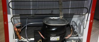
First of all, all household appliances that have a compressor will suffer. The latter simply will not start at low voltage. This is fraught with the fact that the electric motors of the equipment quickly begin to overheat. And having reached a critical state, they completely fail.
See also: Catalog of companies that specialize in complex installation of internal engineering systems
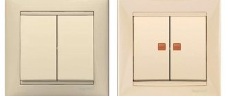
Phase control relay Schneider
The Schneider company is considered one of the best manufacturers of devices in the electrical power industry. The products of this company are actively used both at civilian sites and in large industrial organizations.
The advantages of the company's products include a flexible pricing policy, high quality and special conditions for customers.
The company produces circuit breakers, fuses, load switches and switchboard equipment.
In addition, the Schneider plant produces relays, switches, sockets, contactors and many other devices.
Popular models include relays:
- Control of 1-phase voltage (from 65 to 260 V and time delay from 0.1 to 10 s - RM17UBE
- 3-phase voltage control (208 to 480 V) - RM17TE
- 1-phase voltage control (160 to 280 V, 30 second delay) - EZ9C
- 3-phase voltage control (from 208 to 480 V) - RM17TT00 and others.
Causes of problems
There are three factors that cause voltage drop:
- When the phase is shorted to neutral, 380 Volts will appear in the socket.
- If a zero break occurs and the load in the network is low, then the voltage will sharply tend to the peak.
- There may be a voltage imbalance in the phases.
Low voltage Source uk-parkovaya.ru
In the latter case, an unevenly distributed load leads to the fact that the busiest line will suffer. The voltage will drop to critical. And this is fraught with local problems in the technology itself. And, as a rule, if there is no surge protection relay on the line, then the refrigerator or air conditioner will be the first to suffer.
In rare cases, electricians are to blame for a zero break. The wire can be damaged due to inexperience and carelessness. More often the latter fades away from old age. The provided protection will de-energize the line and disastrous consequences will not occur. There will be temporary inconvenience until the network is restored.
But, if there is no voltage cut-off, then a real mess ensues in the house. In some rooms, the voltage in sockets drops to 50-100 units. In other apartments it rises sharply to 300-350. Moreover, the result is completely local and depends on the specific load on the home line.
A sharp increase in voltage Source uk-parkovaya.ru
As a result, some owners' household equipment simply stops working. Those less fortunate will have to take it for repairs. But after a critical power surge, it happens that repairing the device becomes unprofitable. And then all that remains is to buy a new one. And, as a rule, there is no one to file a claim with.
Overvoltage due to switching
This phenomenon can occur when devices that produce a high inductive load are connected to or turned off in the line. These include power supplies, electric motors, and powerful tools powered from the mains.
This effect is due to the laws of commutation. An instantaneous change in the current value in the solenoid, as well as the potential difference across the capacitor, cannot occur. When a circuit with such a load is connected or opened, the appearance of an electric potential caused by self-induction and switching processes is noted at the point of contact.
The transient process is always accompanied by a surge of voltage, which has the opposite polarity to the input. The small capacitance of the conductors in the network causes a resonance that lasts a short time and causes high-frequency oscillations. At the end of the transition process they fade out.
How long the overvoltage will last and what its magnitude will be depends on the following indicators:
- Load inductance.
- Instantaneous value of the potential difference during switching.
- Capacity of connecting electrical cables.
- Reactive power.
How protection works
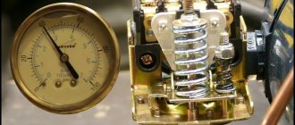
The operating principle of a voltage relay is simple. The device has a built-in network load monitoring unit. Control parameters are usually set by the manufacturer. But the owner has the right to set his own limits.
The block is constantly busy measuring the voltage on the line. And if it deviates from the norm in any direction, then a signal is instantly sent to the executive module. The latter immediately switches off the load on the line, saving working devices.
But the measuring unit continues to operate in cyclic mode. After a certain period of time, the module takes readings from the line. If violations persist, then the automation is inactive. She waits for the next time period for measurements.
Voltage monitoring device Source prom.st
It can also be installed manually. Or leave the factory settings. When the measurements show the specified norm, the executive unit is also notified about this. And it closes the power contact, renewing the connection to external power sources.
Advantages and disadvantages
Each type of relay has its pros and cons:
- Sentinels or anchors. Their big advantage is their almost complete independence from third-party power supply and truly iron-clad reliability. The downside is that sooner or later, if left unattended, the mechanism may malfunction or fail altogether. Again, the connection of contacts over time in such devices occurs directly, which means there is a chance of a spark occurring. Which, in turn, limits the application niches of a mechanical timer - in any fire-hazardous environment, this factor creates many problems.
Anchor time relay EV-142
- Motor. Such time relays have the advantages of mechanical ones, but also the same disadvantages - eventual (albeit not quick) failure and spark connections.
Motor time relay RVT-1200
- Pneumatic or hydraulic. They are reliable, but they are large in size, which is due to the volume of the damper chamber. Among other things, the accuracy of setting time intervals on them is relatively low and requires the participation of a trained specialist. That’s why such relays are used only in industries that have their own staff of adjusters.
Pneumatic time relay RVP-72
- Electromagnetic. Despite the simplicity of their design, they have a significant drawback - the accuracy of adjustment to time intervals is very difficult and varies in each device, regardless of the number of turns of the control screws. That is, in other words, by turning the screw ten times and setting the time on one device, turning the same regulator ten times on another cannot achieve the same response period as the previous one.
Modern electromagnetic relay
- Electronic. Currently, such devices are replacing all previous models. They are practically devoid of disadvantages, are relatively accurate in setting, and the line connection in such devices occurs using a non-contact method. The only disadvantage noted by users of this type of timers is the ease of setting delay periods.
Example of a simple electronic relay
- Brain teaser. They represent the development of electronic options, with better display, more convenient control, as well as the possibility of using them as parts of a “smart home”. The time scale on logical devices is limited only by the depth of the embedded program. An additional plus is that the logical elements they contain can be triggered not only by time intervals, but also by external control pulses-signals from sensors or controllers. The only negative so far is the price - it is a little higher than for just electronic ones. Setting up such time relays is already called programming.
Example of a programmable time relay
Selection of protective automation
Overvoltage relays can be classified according to three criteria. Pay attention to the location and dimensions. Take into account the capabilities of the device. As well as the number of phases in the electrical network. Due to these indicators, the installation of the device differs in many ways.
And when choosing protective automation, people usually pay attention to:
- operating range in volts;
- maximum power;
- passing current;
- speed of network shutdown when an alarm signal is given;
- delay before re-supplying electricity;
- presence of indication.
An important factor is the presence of manual settings. Many apartment owners are not satisfied with the parameters set by manufacturers. And they would like to independently set the upper and lower thresholds for triggering the automation.
Adjustable voltage control relay Source prom.st
Phasing
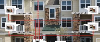
Since the power supply system may differ, the devices are divided into single-phase voltage control relays and three-phase ones. Apartments and most private cottages are equipped first. They work with networks with a voltage of 220 V.
Three-phase protection is mainly used in industry. For example, they protect machines that use several phases for their operation. Moreover, in some cases, phase synchronization is additionally controlled.
Three-phase relays are also used in private homes if the voltage circuit has 380 Volts. But the device has a feature that has a negative effect when used at home. The protection is triggered if oscillation occurs in any of the three phases, which is not critical on a private line. But for production, such a safety net is often a plus. Although in many cases you can easily do without it.
Listening
Lee de Forest had an unusual upbringing for a Yale student.
His father, the Rev. Henry de Forest, was a Civil War veteran from New York, a Congregational church pastor, and a great believer in spreading the divine light of knowledge and justice as a preacher. Obeying the call of duty, he accepted an invitation to become president of Talladega College in Alabama. The college was founded after the Civil War by the American Missionary Association, based in New York. It was intended to educate and mentor local black residents. There Lee felt himself between a rock and a hard place - local blacks humiliated him for his naivety and cowardice, and local whites for being a Yankee. And yet, as a young man, de Forest developed a strong sense of self-confidence. He discovered a penchant for mechanics and invention - his scale model of a locomotive became a local miracle. As a teenager, while studying at Talladega, he decided to devote his life to invention. Then, as a young man and living in the city of New Haven, the pastor's son cast off his last religious beliefs. They gradually left due to their acquaintance with Darwinism, and then they were blown away like the wind after the untimely death of his father. But the sense of his destiny did not leave de Forest - he considered himself a genius and strived to become the second Nikola Tesla, a rich, famous and mysterious wizard of the era of electricity. His Yale classmates considered him a smug windbag. He may be the least popular man we've ever met in our history.
de Forest, c.1900
After graduating from Yale University in 1899, de Forest chose to master the emerging art of wireless signal transmission as a path to wealth and fame. In the decades that followed, he stormed this path with great determination and confidence, and without any hesitation. It all started with the collaboration of de Forest and his partner Ed Smythe in Chicago. Smythe kept their enterprise afloat with regular payments, and together they developed their own radio wave detector, consisting of two metal plates held together by glue that de Forest called "paste" [goo]. But de Forest could not wait long for rewards for his genius. He got rid of Smythe and teamed up with a shady New York financier named Abraham White [who ironically changed his name from his birth name, Schwartz, to hide his shady dealings. White/White – (English) white, Schwarz/Schwarz – (German) black / approx. translation
], opening the De Forest Wireless Telegraph Company.
The company's activities themselves were of secondary importance for both of our heroes. White took advantage of people's ignorance to line his pockets. He swindled millions out of investors struggling to keep up with the expected radio boom. And de Forest, thanks to the abundant flow of funds from these “suckers,” concentrated on proving his genius through the development of a new American system for wireless information transmission (in contrast to the European one developed by Marconi and others).
Unfortunately for the American system, the de Forest detector did not work particularly well. He solved this problem for a time by borrowing Reginald Fessenden's patented design for a detector called a "liquid baretter" - two platinum wires immersed in a bath of sulfuric acid. Fessenden filed a lawsuit over patent infringement - and he obviously would have won this lawsuit. De Forest could not rest until he came up with a new detector that belonged only to him. In the fall of 1906, he announced the creation of such a detector. At two separate meetings at the American Institute of Electrical Engineering, de Forest described his new wireless detector, which he called the Audion. But its real origin is in doubt.
For a time, de Forest's attempts to build a new detector revolved around passing current through a Bunsen burner flame, which he thought might be an asymmetrical conductor. The idea, apparently, was not crowned with success. At some point in 1905, he learned about the Fleming valve. De Forest got it into his head that this valve and its burner-based device were fundamentally no different - if you replaced the hot thread with a flame, and covered it with a glass bulb to confine the gas, you would get the same valve. He developed a series of patents that followed the history of pre-Fleming valve inventions using gas flame detectors. He apparently wanted to give himself priority in the invention, bypassing Fleming's patent, since work with the Bunsen burner preceded Fleming's work (they had been going on since 1900).
It is impossible to say whether this was self-deception or fraud, but the result was de Forest's August 1906 patent for "an empty glass vessel containing two separate electrodes, between which exists a gaseous medium which, when sufficiently heated, becomes a conductor and forms a sensing element." The equipment and operation of the device are due to Fleming, and the explanation of its operation is due to De Forest. De Forest eventually lost the patent dispute, although it took ten years.
The eager reader may already be wondering why we are spending so much time on this man whose self-proclaimed genius was passing off other people's ideas as his own? The reason lies in the transformations that Audion underwent in the last few months of 1906.
By then, de Forest had no job. White and his partners avoided liability in connection with Fessenden's lawsuit by creating a new company, United Wireless, and loaning it American De Forest assets for $1. De Forest was kicked out with $1,000 in compensation and several useless patents in his hands, including the patent for Audion. Accustomed to a lavish lifestyle, he faced serious financial difficulties and desperately tried to turn Audion into a big success.
To understand what happened next, it is important to know that de Forest believed he had invented the relay - in contrast to the Fleming rectifier. He made his Audion by connecting a battery to a cold valve plate, and believed that the signal in the antenna circuit (connected to the hot filament) modulated a higher current in the battery circuit. He was wrong: these were not two circuits, the battery simply shifted the signal from the antenna, rather than amplifying it.
But this error became critical, since it led de Forest to experiments with a third electrode in the flask, which was supposed to further disconnect the two circuits of this “relay”. At first he added a second cold electrode next to the first, but then, perhaps influenced by the control mechanisms used by physicists to redirect beams in cathode-ray devices, he moved the electrode into position between the filament and the primary plate. He decided that this position could interrupt the flow of electricity, and changed the shape of the third electrode from a plate to a wavy wire that resembled a rasp - and called it a “grid”.
1908 Audion triode. The thread (broken) on the left is the cathode, the wavy wire is the mesh, the rounded metal plate is the anode. It still has threads like a regular light bulb.
And it really was a relay. A weak current (such as that produced by a radio antenna) applied to the grid could control a much stronger current between the filament and the plate, repelling charged particles that tried to pass between them. This detector worked much better than the valve because it not only rectified, but also amplified the radio signal. And, like the valve (and unlike the coherer), it could produce a constant signal, which made it possible to create not only a radiotelegraph, but also a radiotelephone (and later - the transmission of voice and music).
In practice it didn't work particularly well. De Forest audios were finicky, burned out quickly, lacked consistency in production, and were ineffective as amplifiers. In order for a particular Audion to work correctly, it was necessary to adjust the electrical parameters of the circuit to it.
Nevertheless, de Forest believed in his invention. He formed a new company to advertise it, the De Forest Radio Telephone Company, but sales were scant. The biggest success was the sale of equipment to the fleet for intra-fleet telephony during the circumnavigation of the Great White Fleet. However, the fleet commander, having no time to get de Forest's transmitters and receivers to work and to train the crew in their use, ordered them to be packed up and left in storage. Moreover, De Forest's new company, led by a follower of Abraham White, was no more decent than the previous one. To add to his misfortunes, he soon found himself accused of fraud.
For five years, Audion achieved nothing. Once again, the telephone would play a key role in the development of the digital relay, this time rescuing a promising but untested technology that was on the verge of oblivion.
Video description
The video will show how a single-phase voltage relay works, which one is better to choose based on the test results:
Device dimensions
All products are divided into 3 types:
- Adapter for one socket. Protects only one device connected through it.
- An extension cord where there can be from one to six sockets. In this case, the protection extends to an entire group of devices.
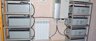
- Bag holder for DIN rail. It is mounted in a common electrical panel and controls the entire electrical supply system of the apartment.
The latest version of a 220 V voltage relay for the home is not only the most functional. It is also the most suitable in terms of design, since all devices are hidden from view. And the devices from the first two points most often have large sizes. And most often it is not possible to make them more compact so that they do not spoil the interior of the home.
Basics and additional features
In most modern protective automatic equipment, voltage control is carried out by a microprocessor. Cheap analogues of relays operate on the basis of a conventional comparator. The microprocessor allows for precise adjustment of the device. Including stepless manual adjustment for response thresholds.
Surge protection device Source psk-remont.ru
Also, devices may have different indications. In simple designs, only a pair of LEDs are built in, which indicate the voltage at the output and input. All modern models have a display on the body that shows the voltage. It can also show specified response thresholds.
Available connection diagrams
In the panel, a single-phase voltage relay is mounted after the meter. It must be placed in the break of the phase wire. Because only the device should control the voltage. And cut off the phase if necessary.
There are two connection diagrams. It is more common to install relays under direct load. But you can connect an additional magnetic contactor to it. When installing the device, the main thing is not to confuse the connection of wires to the input and output. True, this is difficult to do, since there are only three terminals on the automation body, and they are all labeled - input, zero, output.
Devices with different rated power are available for sale. Therefore, there will be no problems in selecting the right one for your home network. But it is always possible to install several low-power relays using a parallel circuit. In this case, only its own group of electrical appliances is connected to each controller.
pros
- In the private sector with overhead power lines and a weak transformer (where the average is 160-180 V), this is simply an irreplaceable thing, especially in my case. Frequent jumps due to wind, welding, etc. A conventional relay is constantly turned off because there is no delay. When TOMZN TOVPD1-63 was installed, I had to set the lower limit to a minimum of 145 V and dream of such functionality as a shutdown delay. TOMZN DDS238-VAP 80A has it all. I installed it on 09.09.19, while there was no wind - I’ll see how the new one copes! Three months - everything is OK. There was also a squally wind, until there was an accident on the main line.
- The price is even cheaper than the first one (possibly due to the $ exchange rate). TOMZN TOVPD1 — 631.38 rubles or $14.85. TOMZN DDS238-VAP 80A - 967.13 rubles or $14.35. Domestic analogues are 2.5–3.5 times more expensive!
How to set up devices
The simplest designs have preset response thresholds set by default by the manufacturer. As a rule, the operating range of the relay is from 170 to 265 V. The parameters may differ, so when choosing, you need to pay attention to them, since it will not be possible to reconfigure later.
Adjustable relays have 3 settings:
- The lower threshold for triggering is set.
- The maximum voltage value is selected.
- Sets the delay period before turning on again.
Connecting a voltage relay is a serious process. But setup requires even more responsibility. It is necessary to study all the household equipment used in the house. And only then set the thresholds. As for turn-on delays, a compromise will have to be found there.
If appliances with a compressor (refrigerator, air conditioner) have priority in protection, then the voltage re-supply time must be set to quite long. From a couple of minutes. And in some cases even bring it to five. This will protect the devices from sudden voltage surges.
Extension cord with controller Source prom.st
But if only a TV and a computer are protected, then a delay of only 10-20 seconds is sufficient. For adjustments, smooth regulators are provided on the body. Modern devices are equipped with convenient sensors.
Some experts recommend connecting a voltage stabilizer rather than a control relay. This is motivated by the fact that in addition to the functions of the latter, it also equalizes the voltage. Therefore, more reliable protection is obtained.
But the stabilizer has significant disadvantages:
- It makes noise when working.
- Takes up a lot of space due to its bulkiness.
- Does not allow fine tuning.
- Increases the network current and thereby creates a danger for unprepared wiring.
- If the grounding is broken, the voltage surge remains unattended.
- Its cost is much higher than a conventional relay.
Therefore, they are accustomed to using a voltage stabilizer only locally. For example, to protect only one refrigerator.
Without wires
Let's fast forward 20 years into the future, to 1904.
At this time in England, John Ambrose Fleming was working on instructions from the Marconi Company to improve a radio wave receiver. It is important to understand what radio was and was not at this time, both in terms of instrument and practice. Radio was not even called “radio” back then, it was called “wireless”. The term "radio" only became prevalent in the 1910s. Specifically, he was referring to wireless telegraphy - a system for transmitting signals in the form of dots and dashes from sender to recipient. Its main application was communication between ships and port services, and in this sense it was of interest to maritime authorities around the world.
Some inventors of the time, notably Reginald Fessenden, experimented with the idea of the radiotelephone - transmitting voice messages over the air in a continuous wave. But broadcasting in the modern sense did not emerge until 15 years later: the transmission of news, stories, music and other programs for reception by a wide audience. Until then, the omnidirectional nature of radio signals was seen as a problem to be solved rather than a feature that could be exploited.
The radio equipment that existed at that time was well suited for working with Morse code and poorly suited for everything else. The transmitters created Hertzian waves by sending a spark across a gap in the circuit. Therefore, the signal was accompanied by a crackle of static.
The receivers recognized this signal through a coherer: metal filings in a glass tube, knocked together under the influence of radio waves into a continuous mass, and thus completing the circuit. Then the glass had to be tapped so that the sawdust would disintegrate and the receiver would be ready for the next signal - at first this was done manually, but soon automatic devices appeared for this.
In 1905, crystal detectors, also known as cat's whiskers, were just beginning to appear. It turned out that simply by touching a wire to a certain crystal, for example, silicon, iron pyrite or galena, it was possible to snatch a radio signal from the air. The resulting receivers were cheap, compact and accessible to everyone. They stimulated the development of amateur radio, especially among young people. The sudden surge in airtime occupancy that arose as a result of this led to problems due to the fact that the radio airtime was divided among all users. Innocent conversations between amateurs could accidentally intersect with the negotiations of the marine fleet, and some hooligans even managed to give false orders and send signals for help. The state inevitably had to intervene. As Ambrose Fleming himself wrote, the advent of crystal detectors
immediately led to a surge in irresponsible radiotelegraphy due to the antics of countless amateur electricians and students, necessitating strong intervention by national and international authorities to keep things sane and safe.
From the unusual electrical properties of these crystals, the third generation of digital switches will in due time emerge, following relays and lamps - the switches that dominate our world. But everything has its time. We have described the scene, now let's return all attention to the actor who has just appeared in the spotlight: Ambrose Fleming, England, 1904.
Briefly about the main thing
To protect home equipment from network overloads, it is necessary to install protective automatic equipment in it. You can use a regular relay that will control the voltage. The device will constantly measure the readings of the latter. And if you deviate from the set norm, independently disconnect from the power source.
You can provide protection to each individually connected household device. For this, special adapters and extensions are produced. But it is more reasonable to protect the entire home electrical network from overvoltage by installing one relay directly in the apartment’s electrical panel.
Connecting the automation is simple. The relay is installed immediately after the meter, breaking the phase wire. The main attention is paid to setting up the device. Reliable protection will be provided by setting upper and lower response thresholds. As well as the delay time before turning on again.
Ratings 0
Types
The most popular types of relays designed for phase control include EL models of the following series - 11, 12, 13, 11MT and 12MT.
It is important to take into account that the scope of application of the product depends on their types of voltage phase control relays (EL):
- 11 and 11 MT - protection of power supplies, participation in the automatic transfer system, power supply of converters and generator sets.
- 12 and 12MT - to protect cranes with a power not exceeding 100 kW.
- 13 - used when connecting electric motors of a reversible type with a power of up to 75 kW.
The devices are fixed on a special DIN rail or only with screws (depending on the situation).