The original design solution of a table lamp often determines its price and popularity on the market. Everyone wants the chosen product to serve without fail and for a long time. However, technology is technology, sooner or later breakdowns may occur and you have to think about how to fix the lamp.
In such cases, it is not necessary to take the lamp to the workshop. If you have at least a school understanding of electrical engineering and the ability to hold a screwdriver with pliers in your hands, most faults can be identified and repaired yourself at home. We'll tell you how to do this in the article.
Lamp device
Cylindrical fluorescent lamps
A fluorescent counting source is a lighting device in which ultraviolet radiation is converted into visible light of a certain spectrum. The glow is achieved thanks to an electrical discharge that appears when electricity is supplied in a gaseous environment. Ultraviolet light is generated, which affects the phosphor. As a result, the light bulb lights up and begins to shine.
Most fluorescent lamps are manufactured in the form of cylindrical tubes. More complex geometric shapes of the flask may be found. Along the edges of the tube there are tungsten electrodes, which are soldered to the outer pins. It is to them that the voltage is supplied.
The flask is filled with a mixture of inert gases with negative resistance and mercury vapor.
Structure of a fluorescent lamp
The standard light bulb circuit consists of a starter and a choke. Additionally, various control mechanisms can be used. The main task of the inductor is to generate a pulse of the required size, which can turn on the lamp. The starter is a glow discharge whose electrodes are in an inert gas environment. A prerequisite is that one electrode must be a bimetallic plate. If the lamp is off, the electrodes are open. When voltage is applied they close.
Classification is carried out according to different criteria. The main one is light. It can be day or white with different color temperatures. The division is also made along the width of the tube. The larger it is, the higher the lamp power and the area of the illuminated area. Fluorescent lamps are divided according to the number of contacts, operating voltage, presence of a starter, and shape.
The simplest electrical circuit
To repair lighting devices, you need to know at least the general principles of constructing electrical circuits. Modern lamps are equipped with many additional electronic mechanisms and have a variety of functionality. However, the principle of connecting a lighting device (light bulb) almost always remains the same.
The simplest electrical circuit of a lamp.
The figure shows diagrams of different types of lamps with several light sources, but they are also typical for table lamps.
An important feature, especially for desktop models, is the ability to adjust the brightness and intensity of lighting. It is these devices that are widely used for students, creative workers and in the electronics industry for the assembly of small parts and precision mechanisms. In such models, the electrical circuits are somewhat more complex and include additional elements for adjusting the lighting.
Brightness control circuit, where S2, S3, S4 are step controllers.
Principle of operation
Operating principle of a fluorescent lamp
Supply voltage is supplied. At the initial moment, no electric current flows, since the medium has high resistance. The current moves through the spirals, heats them and is supplied to the starter. A glow discharge appears. After heating the contacts, the bimetallic plates close. The temperature on the bimetallic part drops and the contact in the network opens. This leads to the fact that the choke creates the necessary impulse as a result of self-induction, and the lamp begins to shine. The arc discharge is maintained by thermionic emission occurring on the surface of the cathode. The electrons are heated by current, the magnitude of which is limited by the ballast.
Light appears due to the fact that a special substance is applied to the lamp - a phosphor. It absorbs ultraviolet radiation and produces a certain range of glow. The color can be changed by applying phosphors of different composition to the flask. They can be made from calcium halophosphate, calcium-zinc orthophosphate.
The main advantages of the lamp are energy savings, long service life, and bright light. Disadvantages include the inability to connect directly to the network and the presence of mercury inside the flask. Lamps are more expensive than incandescent light bulbs, but cheaper than LED light sources.
Energy saving light bulb - the same LDS
Almost everyone has seen, and many have used, so-called energy-saving light bulbs, which are screwed into a regular lighting socket. Their resemblance to luminescent ones is simply amazing - the same tube, only small and twisted.
This is also an LDS, only more compact and convenient.
This similarity is not accidental, since an “energy saving device” is a conventional LDS with an electronic ballast. You can verify this simply by disassembling the failed “saving bank”:
Disassembled energy saving light bulb
Even in the photo it is clearly visible that the bulb has 4 terminals - 2 for each spiral - and is connected to a compact, but very ordinary electronic ballast. You can even verify experimentally that the ballast is the most common. Take a regular tubular LDS with the same power as indicated on the “energy saving” base and connect it instead of the original one. Neither the lamp nor the electronic ballast will even notice the change.
This hybrid assembly can be useful if an energy-saving light bulb breaks or its spirals burn out. Why throw away perfectly serviceable electronics when tubular LDS is very inexpensive?
A tubular gas-discharge lamp connected through an “energy-saving” ballast. If you understand the different connection schemes, you can do everything yourself, saving both time and money.
Connection methods
There are various options for connecting a fluorescent lamp to the network. The most popular scheme for a fluorescent lamp is connection using an electromagnetic ballast.
Circuit with electromagnetic ballast (EMB)
Circuit with electromagnetic ballast (EMB)
The operating principle of this circuit is based on the fact that when voltage is applied to the starter, a discharge occurs, leading to the short circuit of the bimetallic electrodes. The electric current in the circuit is limited by the internal inductive resistance. This leads to the fact that the operating current increases almost 3 times, the electrodes heat up sharply, and after the temperature decreases, self-induction occurs, leading to the ignition of the starter fluorescent lamp.
Disadvantages of a fluorescent lamp circuit with electronic ballasts:
- High energy costs compared to other methods.
- Long startup time - approximately 1-3 seconds. The more worn the light bulb is, the longer it will take to light.
- Does not work at low temperatures. This makes it impossible to use in a basement or garage that is not heated.
- Stroboscopic effect. Flicker negatively affects human vision and the psyche, so such lighting is not recommended for use in production.
- Humming noise when working.
The circuit provides one choke for two light bulbs. Its inductance is enough for both light sources. The starter voltage is 127 V; for a lamp with one lamp, a voltage of 220 V is required.
There is a circuit for a 220 V fluorescent lamp with a chokeless connection. It does not have a starter. This starterless connection is used when the filament of a light bulb burns out. The design also includes a transformer and a capacitor to limit the current. For lamps with a burnt-out filament, there are circuit modifications without a transformer. This makes the design easier.
Two chokes and two pipes
Choke
This method is used for two lamps. The elements must be connected in series:
- Phase - to the inductor input.
- From the throttle output, connect one contact to the first lamp, the second to the first starter.
- From the first starter, the wires go to the second pair of contacts of the first lamp, the free wire must be connected to zero.
The second lamp is connected in the same way.
Connecting two lamps from one choke
Circuit for two fluorescent lamps
This option is not used often, but it is not difficult to implement. The two-lamp serial connection is distinguished by its economy. For implementation, you will need an induction choke and a pair of starters.
Connection diagram for fluorescent lamps from one choke:
- A starter is connected to the pin output of the lamps using a parallel connection.
- Free contacts are connected to the electrical network through a choke.
- Capacitors are connected in parallel to the light sources.
Budget switches may periodically stick due to increased starting currents. In this case, it is recommended to use high quality switching devices. This will ensure long and stable operation of the fluorescent lamp.
Circuit with electronic ballast
Electronic ballast connection diagram
All the disadvantages of the electronic ballast led to the fact that I had to look for another connection method. As a result, the electromagnetic ballast was replaced with an electronic one, operating not at the mains frequency of 59 Hz, but at a high frequency of 20-60 kHz. Thanks to this solution, flickering of the light is eliminated. Such schemes are used in production.
Visually, the ballast is a block with terminals. Inside there is a printed circuit board on which the electronic circuit is assembled. An important advantage of electronic ballast is its miniature size. You can even place the block in a small light source. Also, the startup time is shorter and the device operates silently. The method with electronic ballast is also called starterless.
It is not difficult to assemble a circuit for such a device. It is usually located on the back of the device. The diagram indicates the number of light bulbs for connection, all explanatory notes, and information about technical characteristics.
How to connect a fluorescent lamp:
- Contacts 1 and 2 – to a pair of contacts from the lamp.
- Contacts 3 and 4 are for the remaining pair.
The input must be supplied with supply voltage.
Circuit with voltage multipliers
To increase the service life, a method without electromagnetic ballast can be used. The operating time is extended provided that the lamp power does not exceed 40 W. The filaments may be burnt out - they should be short-circuited in any situation.
This circuit allows you to rectify the voltage and double it. The lamp lights up immediately. To implement the circuit, you need to choose the right capacitors. 1 and 2 are selected for 600 V, 3 and 4 – for 1000 V. The disadvantage is the large size of the capacitors.
Connection without starter
The starter causes additional heat in the fluorescent lamp. It also often fails, which is why this part has to be replaced. There are schemes in which the fluorescent light source operates without a starter. The electrodes are heated to the required level using transformer windings that act as ballast.
When buying a light bulb, you need to pay attention to the inscription RS - quick start. These are the products that work without a starter.
Circuit with serial connection of two lamps
Circuit for connecting two lamps in series
There are two lamps that need to be connected using one ballast in a series manner. To perform such work you will need the following components:
- Induction choke.
- Two starters.
- Two fluorescent lamps.
The connection diagram for the fluorescent lamp is as follows:
- A starter is connected to each lamp in parallel to the pin input at the end of the bulb.
- The remaining contacts should be connected to the electrical network via a choke.
- Capacitors are connected to the contacts of the light bulbs. They are necessary in order to reduce the intensity of interference and reactive power.
Capacitors are selected based on the load.
Advantages of different types of ballasts
Before choosing and, especially, buying ballast of one type or another, it makes sense to understand their differences from each other. The advantages of EmPRA include:
- moderate cost;
- high reliability;
- Possibility of connecting two lamps of half power.
Electronic ballasts appeared much later than their throttle counterparts, which means they have a longer list of advantages:
- small dimensions and weight;
- with the same light output, energy consumption is 20% lower than that of electronic ballasts;
- almost do not heat up;
- operate absolutely silently (EMPRA often hums);
- no lamp flickering at mains frequency;
- lamp life is 50% higher than with a choke;
- The lamp starts instantly, without “blinking”.
But, of course, you have to pay for all these advantages - the cost of an electronic device is significantly higher than the price of a throttle device, and reliability, alas, is still lower. In addition, if the power of the electronic ballast is lower than the power of the lamp, then, unlike the electromagnetic one, it will simply burn out.
Replacing fluorescent lamps
To remove the fluorescent lamp, you need to turn it in the direction indicated on the holder.
The fluorescent light source differs from classic halogen lamps and products with filament in its long service life. But even such reliable light bulbs can fail, which is why they have to be replaced.
You can perform the replacement as follows:
- Disassemble the lamp. It is important to carefully remove all parts so that the device is not damaged. The fluorescent tubes must be rotated around their axis in the marked direction. It is indicated on the holder by arrows.
- After turning 90 degrees, the tube should be lowered. Then the contacts will easily come out of the corresponding hole.
- Visually inspect the integrity of the light bulb and filaments. If there are no visual problems, the failure may be caused by internal components.
- You should take a new light source. Its contacts must be in a vertical position and placed in the hole. After installing the light bulb, you need to turn it in the reverse position.
You must remove the device carefully so as not to break the glass flask. There is mercury inside, which is hazardous to health.
After the system is assembled, you can apply the supply voltage, turn it on and begin testing. The final step is to install a protective shade on the lamp.
Before you start repairs
If a table lamp breaks, the first thing you need to do is disconnect it from the power supply and remove the plug from the socket. All repair work, including inspection, must be carried out with the lamp completely disconnected from the power supply. Indeed, in the event of an insulation breakdown, exposed wires can come into contact with the metal elements of the lamp body, and if they touch, you will receive an electric shock.
You should not touch its metal parts immediately after turning off the lamp; this is unsafe. Capacitors retain a static charge for some time, and if the insulation is broken, the product body may become energized. We need to wait for the capacitors to discharge! The lack of current in the switched off lamp is checked with a voltmeter, and only after that can the repair begin.
Typical design of a table lamp.
If the lamp uses an incandescent lamp, it is important to remember that during operation it heats up and can heat nearby elements, including the metal lampshade. Wait until the lamp cools down to avoid burns when touched.
For this reason, table lamps do not use bulbs with more than 60 watts of power.
You should handle the light bulb carefully when unscrewing it; it may crack in your hands. There is no need to screw the light bulb into the socket too tightly - unscrewing it after prolonged use at high temperatures will not be easy, and this often ends in the socket breaking.
Functionality check
Testing the electrodes with a multimeter
You can check the assembled system using a tester that checks the filaments. Its permissible resistance should be 10 ohms.
If the test device shows infinite resistance, the bulb is only suitable for cold start use. Infinity may also be displayed if the light source is faulty. The normal resistance that the tester should show reaches several hundred ohms. This is due to the fact that in the normal state the starter contacts are open. In this case, the capacitor does not pass direct current.
If you touch the choke terminals with the multimeter probes, the resistance will gradually drop to a constant value of several tens of ohms.
The exact value cannot be determined using a conventional tester. But some devices have a function for measuring inductance. Then the values can be checked using the EMPR data. If they do not match, problems with the device can be judged.
What it is
Luminescent devices look like a glass vessel, which can have a different appearance, matte color with connection contacts protruding at the ends.
Different shades of glow
The configuration of luminescent products can be a tube, torus, or spiral type. When making the surface of the lamp, a vacuum environment is created in it and filled with an inert gas. It is the reaction of the inert gas in combination with electricity that makes the glow, producing rays of a cold or warm shade, which is usually called daylight. Therefore, LLs are called daylight devices.
Bottom line
In this article, we examined in detail the typical malfunctions of monitors and their self-repair with examples.
Repair cost
The cost of repairs depends on the availability of parts and their cost. Service centers can charge from 500 rubles for work. A warranty is added to this price, which is usually from 1 month.
When repairs are not cost-effective
If the matrix is broken, repair is not profitable. Its cost starts from 70% of the cost of the entire monitor.
Useful videos on repairs
Post Views: 1,882
Operating principle of electronic ballasts
Electronic ballasts (EPG) use the potential of modern power electronics and are more complex, but also more functional circuits. Such devices allow you to control the three startup phases and adjust the light output. The result is longer lamp life. Also, due to the lamp being powered with a current of a higher frequency (20÷100 kHz), there is no visible flicker. A simplified diagram of one of the popular electronic ballast topologies is shown in Fig. 2.
Rice. 2 Simplified circuit diagram of electronic ballasts In Fig. 2 D1-D4 – mains voltage rectifier, C – filter capacitor, T1-T4 – transistor bridge inverter with transformer Tr. Optionally, the electronic ballast may contain an input filter, a power factor correction circuit, additional resonant chokes and capacitors. A complete schematic diagram of one of the typical modern electronic ballasts is shown in Fig. 3.
Rice. 3 Circuit diagram of BIGLUZ electronic ballasts The circuit (Fig. 3) contains the main elements mentioned above: a bridge diode rectifier, a filter capacitor in the DC link (C4), an inverter in the form of two transistors with wiring (Q1, R5, R1) and (Q2, R2 , R3), inductor L1, transformer with three terminals TR1, trigger circuit and lamp resonant circuit. Two windings of the transformer are used to turn on transistors, the third winding is part of the resonant circuit of the LDS.
Causes of breakdowns
It often happens that table lamps simply stop turning on and working. There are several main reasons for these malfunctions:
- Broken cord. This may be indicated by periodic loss of light or blinking. Very often the main place of damage is near the fork, as it is susceptible to frequent bending.
- Failure of the switch will not allow the circuit to close, which will cause the absence of light.
- Broken wiring near the socket. Very often this occurs due to burnout of contacts that fall out of the clamps.
Diagnosing this is quite simple, which can be done with a routine visual inspection or using special instruments.
Characteristics
Main parameters of fluorescent lamps:
- light bulb power spectrum - from 10 to 90 watts (for household use);
- medium voltage - 220 and 127 V;
- tungsten melting point - 6000K;
- light beam - can exceed 100 Lm/1W;
- base parameters - 1E14 and standard E27;
- vessel size - 14, 18, 28, 38mm;
- service life - from 10,000 to 35,000 hours;
- Efficiency over 20%.
Operating principle
Useful tips
Some practical tips for lamp repair:
- Do not put pressure on the light bulb when screwing it into the socket. The base is made of ductile metal that deforms under pressure. However, halogen bulbs have circular contacts, so they are difficult to damage.
- Halogen lamps rotate endlessly. From a certain moment, when rotating, the glass begins to scroll relative to the base. The problem is the contacts. The new lamps have a shorter thread and do not reach the bottom.
- If the switch is in the off position, the phase should not be directed to the cartridge contacts. If this is not the case, you need to turn off the circuit breaker in the electrical panel (at the entrance).
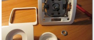
To create contact between the lamp and the base, perform the following steps:
The central contact is turned upward using a screwdriver. The contact pad should be at an angle, not vertical. The lunar contact is usually vertical
Any of the existing petals is carefully lifted (at least a millimeter), focusing towards the periphery of the cartridge. The bent ends are slightly straightened.
Most often, two or three fittings are enough for the lamp to turn on.
Particular attention should be paid to maintaining the edges of the cartridge, otherwise it will have to be replaced
Source
Do-it-yourself repair of lamps and chandeliers with an ordinary socket!
It’s not uncommon to change an energy-saving or regular incandescent light bulb in a lamp (chandelier), but the new one doesn’t light up! You need to immediately ring it or check it in a lamp that is well known to work. If it does not light there either, it is necessary to repair the socket or, less often, check the integrity and connection of the wires or cables in the lamp or the electrical wiring!
Remember, a lamp, especially an incandescent one, heats up to high temperatures! To avoid burns, always wait until it cools down! You should never screw in lamps with a power greater than that indicated in the passport for the lamp or on its socket - this threatens its breakdown and even fire!
Repairing LED and fluorescent lamps has its own characteristics, so we recommend reading our relevant instructions dedicated to this.
Do-it-yourself repair of a ceiling lamp or chandelier:
- Knocks out the machine protection when the lights are turned on:
- It rarely happens that the machine itself breaks down, then it is necessary to replace it.
- Sometimes the cause may be a short circuit (short circuit) in the electrical wiring of the apartment or inside the lamp itself. Ring all the wires to the cartridge contacts in order to find and eliminate the cause of the short circuit. If you find a short circuit near the cartridge or in any other place between the wires, you need to remove the damaged area and cut and connect the wires in a new way.
- Quite rarely, when twisting the lamp, a short circuit occurs between the contacts in the socket. Check and bend the contacts.
- And sometimes, on the contrary, the wire breaks off near the terminal block or socket through which the lamp is connected to the home electrical network. Check and restore.
- If the electrical circuit and lamps are in order, check that the contacts in the socket are touching the lamp . If one or both contacts break or burn, the cartridge must be replaced; if they are intact, simply bend them with a screwdriver.
- A cracking sound is heard and the lamp flashes (very harmful for energy-saving lamps) - this indicates poor contact and sparking in the socket. It is necessary to disconnect the wires and disassemble the socket, clean the terminals with bolts and contacts touching the lamp, and replace in case of severe wear. We put the cartridge back together and connect the wires. If the cartridge has become brittle and crumbles, then it is definitely necessary to replace it with a new one. Sometimes it is often enough to bend the central contact upward.
- Do not unscrew the incandescent light bulb from the socket. Reason: the base is rusted or the central contact is stuck to it. Take thicker gloves or a rag and try to unscrew it! Often, the lamp bulb bursts or falls off, and its base remains in the socket, which can be easily unscrewed by holding the socket by the edge with pliers counterclockwise. If it doesn’t work, disassemble the cartridge as described in the first paragraph.
- Sometimes it's the switch that's at fault, not the light fixture. Instructions for its repair.
Repair instructions for a table lamp.
When repairing a table lamp, we check the integrity of the electrical circuit and socket contacts - everything is as described above, but there are also some peculiarities:
- If the lamp blinks or goes out altogether with any vibration or movement, this indicates a broken cord. The location of the damage can only be found by visual inspection and palpation along the entire length. Pay special attention to where the flexible cable enters the luminaire and near the plug. If you don’t find it, buy a new flexible multi-core cable of the PVS brand, but remember that replacing the flexible power cord of any electrical appliance must be replaced with a new one with the same or larger core cross-section. Failure to comply with this rule can lead to heating of the cord and, in some cases, even fire.
- The lamp may not turn on due to a broken push-button or key switch. Check its functionality by testing the contacts after disassembling or, without disassembling, ring through the wires connected to it. Switches can be built into both the electrical cable and the luminaire body. When found, as a rule, it is not possible to either disassemble it or repair the damage, so I recommend replacing the switch with a new one.
- It is very rare that there is a problem with a lamp plug or electrical outlet . Check and restore contact.
Personally, I check the table lamp in the following way : I plug it into the socket, then the switch, and carefully use a multimeter to measure the presence of 220 Volts at the contacts of the socket. Just be careful not to short circuit.
Note: energy-saving lamps can be supplied with reduced and constant voltage - take this into account when checking.