- Date: 01/31/2015 Rating: 41
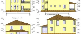
A working drawing of the house support is necessary for high-quality construction work.
To complete the correct drawing of the foundation of a house, you need an engineering education, but everyone should be able to read design drawings.
General documentation for the foundation of a house includes sets of drawings, which are drawn up in accordance with the installation work plan. Each individual document is assigned its own number.
The first sheets of working documentation for the foundation must include data on all working drawings:
All unmarked foundation beams are BF2.
- a summary sheet of drawings, which includes a list of the main set of design documentation; a sheet of specifications for the materials of the foundation of the house; symbols in accordance with GOST and ESKD; general instructions, reference documents and other data, including sketches, estimate documentation, quality certificates and documents for products.
The basis for creating a set of documents is the assignment for the beginning of the design and the project approved by all authorities. The foundation drawing must include the following marks:
- a mark on compliance with all standards, norms, rules and current legislation; a list of works for which it is necessary to draw up acts for hidden work; a mark on passing control for patent purity.
Principles for creating design documentation for the foundation
Foundation drawings include horizontal and vertical sections of the foundation, which demonstrate the configuration of the main elements of the support: columnar foundations, load-bearing wall structures, columns, equipment, etc. General foundation drawings are drawn on a scale of M1:100, as well as M1:200 and M1:400 . To begin with, the main alignment axes, axes of columnar supports and columns are applied to the drawing.
List of parts for one element.
The foundation outline is drawn with lines with a nominal thickness of 0.5 mm (thin) and 1 mm (main). The general plan must show the design configuration of the main base of the house foundation, preparations and bedding for the base, changes in depth and ledges at different laying depths. It is mandatory to display monolithic and prefabricated structural elements.
If the design assumes the presence of technological openings for utilities, then they should be shown on the plan with reference to the nearest axes, drawing the lower part and assigning a serial number to the opening.
These ledges and holes are drawn using invisible contour lines. In some cases, the holes are shaded. All dimensions and references to marks are included in the explication of the design documentation for the house.
Each building foundation drawing includes geodetic marks to determine the “common zero” and indicate the depths of the main sections. If the laying depth has a constant value, then it is indicated in the footnote of the note. Markings of opposite corners of the building and points of intersection of the main axes must be linked to the coordinates marked on the general plan of the site.
In the plans of columnar foundations, when drawing images, the length and width of the pillars are shown, taking into account each ledge of the terrain. The sole is shown separately with the cut width indicated. Dimensions are drawn taking into account the general plan and dimensions of the house.
Return to contents
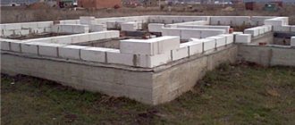
Strip foundations.
To more accurately display the structure of the house supports, cross sections are included in the drawings.
The section plane is filled with shading. Sections are drawn on a scale of M1:50, M1:25 and M1:20, as a rule, on a separate sheet with elements included in the main specification. If the foundation is small in size and has little complexity, the sections are placed on the main sheet together with the foundation plan.
The sections include an image of the main contours of the foundation support, the plinth, the lower part of the wall, the ground level, the blind area of the external walls, waterproofing and technological openings.
One of the conditions is to display the 0.00 mark (common zero). It is advisable to place all marks strictly on the same line. The leader shelves rotate in the opposite direction from the section.
Each drawing of the foundation of the house must have notes on the construction of the foundation, preparatory and waterproofing work. On the right is a table of standard loads on the base and a specification of standard concrete, steel and reinforced concrete components of the support. When constructing a structure from individual elements, an installation plan and layout are drawn up indicating the location of the individual blocks.
The foundation plan is the main guideline when constructing the support of a building. Therefore, the quality of further work depends on its accuracy and information content.
Constructive section: how to draw drawings and diagrams of individual elements
The structural section is an already detailed part of the project, which contains both general and individual data, various layouts of building elements: foundation, staircase structures, floors, trusses. Also included in this part are detailed drawings of all components, which indicate the specifics of products and materials.
The cross-sectional drawing of the foundation deciphers the dimensions of the strip fortifications of the house, the depth of their occurrence and the materials that are necessary for their construction.
The image of the foundation is presented in the form of the following plans and drawings:
- general foundation plan;
- longitudinal section diagrams;
- cross-sectional drawings.
Certain types of drawings provide a cross-section of floor slabs, their longitudinal and transverse sections at different elevations:
- overlap plan at point +0.00;
- at + 3.00;
- at an altitude of +6.00.
At the constructive stage, layout plans for the foundation, floors, and trusses are made.
Assemblies of structural parts are objects of a special structure, including stairs and flights both outside and inside the premises. Accurate calculations for strength and static strength are also given here.
This section of the project contains in separate tables the characteristics and sequence of use of materials, in particular:
- steel reinforcement;
- reinforced concrete elements;
- wooden crossbars.
Conditions for accurately transferring the plan to the area
In order for the drawing to be easily transferred to the area and to mark the site with sufficient accuracy, certain conditions must be met.
Accurate scaling for each part of the plan. When performing enlarged callout images, their scale is indicated separately. For general scaling of foundation plans, ratios of 1:100, 1:200, 1:300, 1:400 are used.
Axial marking will help to significantly simplify the transfer of the diagram to the terrain. The alignment and extreme axes are marked on the general plan and separately for remote views, as well as in places where individual elements (columns, etc.) are installed. It is mandatory to indicate the distance between the extreme axes (of walls or support columns) and the alignment ones.
General plan of the foundation indicating dimensions, materials and required holes.
Simplifies the task of transferring the plan to the terrain and coordinate grid.
What equipment will be needed?
Site planning can be done mechanically or manually.
- In the first case, heavy equipment is rented: a bulldozer or grader, a tractor with a leveling bucket, a tractor with a cultivator.
- When carrying out mechanized independent activities, a walk-behind tractor with a cultivator and a cutter for cutting soil is used.
The cheapest method is manual planning. To carry it out, you will need the following tools: a shovel (scoop and bayonet), a hoe of different sizes, a rake, a crowbar, pegs, a hammer (sledgehammer), an axe, a saw (hacksaw) for removing vegetation. To transport soil you need a wheelbarrow or cart.
Measurements and markings are made using:
- level;
- building level;
- roulettes.
Basic calculation parameters
The foundation drawing must be created on the basis of calculations, which take into account:
- the total weight of the structure being constructed, the degree of load increase during operation, the type of soil on the site (its density, water content, etc.).
Based on these data, not only the geometric parameters of the support are taken into account (depth - for all types, sectional shape and width of the support of a strip-type house, diameter and wall thickness of pile structures), but also materials for manufacturing (grade of concrete and use of fillers, type of reinforcement, device waterproofing).
Specification for additional materials with explanatory notes for the foundation plan.
Sequence of design work
Before starting to draw up a project, it is necessary to make a decision on the purpose of the future object. For example, you should decide whether to build a foundation for a small residential house or pour a foundation for a summer house.
For a house, you should determine how many rooms you plan to arrange. If necessary, guest rooms should be included in the living quarters. The draft layout should include detailed drawings of the foundation.
The foundation drawing must include the entire mass of the object, an indicator of the increase in loads during the operational period, and features of the soil composition. Here it is very important to display the type of soil on which the strength and durability of the future object will depend.
The next stage of project development is to count and indicate all additional structures that are planned to be built on the site. This may include a garage box, storage room, toilet, bathhouse.
Customers who want to create a secluded recreation area on their own territory need a special layout for the placement of the foundation. It is very important for them to position the main facade in such a way as to hide it from prying eyes with landscape decorations.
Before the creation of the foundation plan is completed, the required volume of earthworks to eliminate all uneven places on the territory should be indicated. Now it is possible to proceed to drawing up a general plan and drawing drawings of the foundation on paper.
Proper planning and accurately drawn up drawings make it possible to carry out construction work with significant savings in labor costs and finances.
Features of the implementation of the strip foundation plan
The support plan for a strip-type house should show:
- the configuration of the section, the type and structure of the footing, the laying depth in each section (if the depth of the entire support is equal, the parameter is indicated once, if it is predominantly equal - once with an additional indication of the places of the foundation with a depth different from the general value), the location of utilities (the lower mark of the holes and their diameter can be indicated directly in place, on a remote view or in an explication).
A simple drawing of a strip foundation indicating materials and additional explanations.
When drawing a prefabricated strip base, the coordinates and parameters of the reference block are indicated with maximum accuracy. During installation, it is installed first, the rest are mounted by reference to the reading block.
When making foundations with monolithic and prefabricated sections, their boundaries must be accurately marked on the plan.
Examples of additional reinforcement schemes for strip foundation plans.
Plan of a one-story house up to 100 sq. m – construction of a building for a comfortable life
One-story houses with an attic, up to 100 sq.m. can be an excellent solution for small areas located within the city. Such structures are very popular due to their affordable cost and low physical costs for construction. Moreover, for construction you can use different materials, from wood to concrete blocks.
PHOTO: z500proekty.ru/projekt/z72.html The simplest, modest, but beautiful option
There are a number of advantages of a small house with an attic:
- high speed of construction and design;
- less material costs for foundations and building materials;
- it is easier to provide the entire room with the necessary communications;
- you can order a ready-made project of economy or luxury class;
- the building can be erected on almost any type of soil without fear of destruction or settlement of the house.
PHOTO: z500proekty.ru/projekt/z71.htmlThe design with an attic will provide additional space
The disadvantages include limited space and layout options, since only 3-4 full rooms can fit on the ground floor.
PHOTO: z500proekty.ru/projekt/z7.html Option with a small terrace
Among typical projects, the following dimensions are distinguished:
- 6×6;
- 9×9;
- 8x10 m.
Each design has its own characteristics, and externally can be made in any design, distinguishing your home from others.
Plan of a one-story house 6 by 6 m: interesting photo examples of finished work
Planning a one-story cottage can take a lot of time, but the construction process itself, with a well-prepared plan, will go much faster
In a small house, it is important to take into account the correct arrangement of rooms with the most rational use of the entire living space
Among the plans for small houses 6x6 m with one floor you can find very interesting options. Here are some photographic examples of schemes and finished buildings:
Simple layout
Option with one large living room
House plan 6x6 m with attic floor
You can choose a slightly larger project 6x8 m
The living area in such a modest room is only 36 m², but even in such an area you can arrange a sleeping room and a living room, and move the nursery to the attic. It is better to make the bathroom combined, freeing up space for the kitchen or hallway. Such designs are often chosen by elderly couples or small young families with one child.
Plan of a one-story house 9 by 9 m: photo examples with room distribution options
There are quite a lot of layouts for a one-story house 9 by 9 m, despite the modest living space. You can make a plan yourself or order a ready-made version from the masters. Here are some interesting room layout options:
Location of rooms with two bedrooms
Corner layout. You can make a big porch
Option with terrace
Example with an attic
A one-story house 9 by 9 m can be built from brick, stone, timber, energy-saving panels or foam blocks. The last option is the most affordable. A garage or attic can be added to any structure to make the space larger and more functional.
On average, the total living area will be 109 m², and the facades can be very diverse. Here are some ready-made beautiful houses 9x9 m:
Layout of a one-story house 8 by 10 m with photo
When planning the construction of a house and drawing up a project, it is worth thinking through many nuances, ranging from the number of people in the family, ending with the location of the building on the site with the choice of window location.
Modern technologies make it possible to create 3D designs of one-story houses 8 by 10 m, taking into account their location on the site. To do this, they use special computer programs, where it is even possible to distribute rooms and arrange furniture.
3D design option for the exterior of a house
There are many layouts and options for distributing living rooms; you can choose a project for a one-story 8x10 house with an attic or an attached garage, and also think about the basement. All this allows you to maximize the usable area of the building.
Here are some interesting layouts:
House with attic, ground floor plan
Ready-made designer house made of wood with a large open terrace
3D modeling of the location of the house on the site
Option for the location of rooms with an attic floor
Sections in terms of the foundation
Sections clarify the plan of a strip or pile foundation. They depict:
- geometry (contours of support), waterproofing, blind area (when depicting external walls), dimensions of ledges.
Section of a strip foundation with waterproofing and blind area.
For the tape type, it is necessary to indicate the levels (to make the drawing more clear, marks are placed on the plan at the same level with the shelf turned away from the section). The zero level is considered to be the floor level of the 1st floor. In addition to this, the following levels are indicated:
- surface of the earth, base of the foundation, edge.
To make it easy to establish the cross-sectional location of a strip-type house support, a trace of the secant plane is applied on the general plan - open strokes with arrows indicating the direction.
Principles of room arrangement
The layout of the rooms in a private house determines the level of comfort. Regardless of the number of floors, the mansion is conventionally divided into two zones: day and night or recreation. You can see the options in the house layout photos.
The day part of the project includes:
- kitchen;
- dining room;
- hall.
Designers sometimes include a terrace and veranda in it, where relaxation is carried out in the warm season. There is also a toilet and bathroom here.
In the night rest area there are:
- bedrooms;
- children's;
- wardrobe;
- bathroom with toilet.
Based on this principle, standard layouts of one- and two-story houses have been developed. The first floor is used for active pastime with the whole family. The second one is reserved for night time. If there are people in the family with limited mobility or elderly people, in the design of the first floor they allocate space for a bedroom and build an additional toilet with a shower. This layout is considered convenient, allowing you to fully relax and receive guests at the same time.
There is an opinion that it is better to orient bedrooms towards the southern sides of the house. This layout will allow you to fill the rooms with enough sunlight. The disadvantage is that in the summer the rooms will need air conditioning; this is achieved by installing household appliances and running them constantly.
Additional Documentation
As additional clarifying documentation, the following is attached to the general house foundation plan:
- summary specification of all elements that are located below the zero mark (finished reinforced concrete and concrete products, metal structures, etc.). table of load standards, layout and installation plan (for prefabricated supports), notes and notes regarding the preparatory stage of construction, installation of hydro- and thermal insulation , design features (on separate sheets or on a general plan).
Drawing of a prefabricated strip foundation with a remote section and developments for installing blocks.
What is a residential building project?
A project for an individual residential building is a set of working documentation that is created as an action plan for builders based on a preliminary program approved by the customer. The construction project consists of three parts:
- The architectural part, which includes drawings of the future house. It includes all floor plans (including the basement and attic), plans for facades and sections of the building, plans for the roof, doors and window openings.
- The design part is aimed at the implementation of architectural drawings. This includes plans for the arrangement of all parts of the house (foundation, walls, floors, roof), tables and calculations of the use of building materials. All plans and tables are supplemented with recommendations for carrying out construction work.
- The engineering and technical part includes calculations and drawings for installing utilities into the house (water supply and sewerage, heating system, electrical networks).
Types of projects
All residential building projects are divided into two types:
- Standard projects are intended for repeated implementation and serial construction of buildings of the same type. They are also called ready-made because they are created once and then used as a template. The development of ready-made plans is carried out on the basis of studying the construction market, soil characteristics, weather conditions, specific building materials, taking into account all the necessary building codes and regulations.
- Individual projects. Individual design is the development of design documentation, which is based on the requirements of a specific customer, correctly combined with the features of construction using the chosen technology.
Individual design allows you to realize the client’s wishes, to create not just template housing, but to build a structure that harmoniously fits into a non-standard site. An individual project contains exactly those documents that are necessary for the construction of a specific house - a master plan, facade and floor plans, sections of the building, drawings of all structures and important elements. In addition, for an additional fee, the client can order plans for additional facilities, such as a garage, sauna, summer house.
Pile foundation plan
The drawing of a pile foundation is a marking of a pile field with reference to the coordinate axes. It accurately indicates the position of each support, taking into account the basic rules for creating foundations of that type:
- piles must be placed under the external walls of the house (along the perimeter of the building), supports are required under the internal load-bearing walls, the distance between adjacent supports of the pile foundation in any direction must not exceed the established norm (for a residential building - 3 m).
Plan of a pile foundation with dimensions.
Pile-type grillage foundations are more difficult to construct, but their design helps to evenly distribute the weight of the structure onto the support. When choosing this option, the drawing must contain an installation diagram for the pile foundation grillage, a specification or explanatory notes about the materials required for its manufacture.
Explanatory note
The foundation design must include an explanatory note, in which the developer must include:
- initial parameters for the house design, on the basis of which the loads from the above-foundation part on the foundations are calculated;
- characteristics of the soil conditions of the construction site included in the calculation of the foundation structure;
- other natural and climatic parameters included in the calculations
- (normative and calculated freezing depth, predicted values of heaving deformation of unloaded soils, calculated heaving forces);
- boundary conditions for the structure of the house included in the calculations (level of responsibility of the structure, thermal conditions, absolute and relative heaving deformations permissible for structures of the above-foundation part of the house);
- basic principles of foundation construction technology;
- technical indicators of the foundation design.
In conclusion, it should be noted that obtaining a reliable foundation with significant savings in the cost of its production is possible only through a qualified approach and accurate calculations. Practice has shown that if at first the costs of the foundation seem too high to the developer and he does without design, then the costs of eliminating defects in the building many times exceed the supposedly saved funds. Expensive engineering-geological surveys and a developed foundation design may ultimately turn out to be cheaper than “free” foundation projects. We must always remember the saying about free cheese.
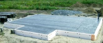
Slab foundation drawing
The most important elements of a slab foundation drawing are:
- heat and waterproofing, reinforcement diagram.
The choice of reinforcement scheme is selected taking into account the design of the support:
- for shallow supports, it is possible to install separate reinforcing elements; to increase strength, it is recommended to bundle them into a single structure; for monolithic supports with a depth of more than 1 m, it is recommended to reinforce the lower and upper zones; prefabricated foundations are reinforced at the joints between elements in the vertical or vertical and horizontal directions.
Rice. 8. Plan of a slab foundation with an extension section.
Plan of a slab foundation with an extension section.
When choosing a combined type of support (a combination of large concrete blocks with poured areas or brickwork), sectors that differ from the overall structure are marked on the diagram.
The drawing of the slab support must necessarily contain markings (indicating the lower point, axial center and diameter) of the holes for supplying utilities.
Reinforcement diagram for slab foundation plan.
Step-by-step instructions for installing MZLF
One of the most popular types of tape for private houses is a shallow foundation. This is a good foundation option that allows you to save on the amount of building materials, reduce the amount of excavation work and general labor investment.
Given the relatively shallow immersion depth, a high-quality survey of the site is required, including test drilling and determination of the groundwater level. This will make it possible to determine the composition of the layers and give grounds to predict the presence of problematic factors, heaving loads, etc.
These actions, as well as the creation of the project, must be performed by a trained specialist.
Further actions are carried out in stages:
Surface marking
The top layer of soil is removed from the site and, if necessary, leveled. Then, using stakes, the corner points of the future tape are marked. Cords are pulled between the stakes, compliance with the design data, orientation to the cardinal points and other parameters is checked.
Be sure to check the correspondence of the lengths of the diagonals. If they are not equal, you need to find the error and correct it in order to obtain high-quality and accurate markings.
Preparing the trench
After the marking has been made, trench digging begins. Excavation is carried out to a predetermined depth. Typically an excavator is used for this purpose, so the corners have to be adjusted and cleaned manually.
The excavated soil is stored on the sides of the trench, but most often it is removed or stored in a separate place.
The width of the trench must provide enough space for the installation of formwork, for which it is usually taken 30 cm larger than the design width of the tape.
Pillow for strip foundation
The sand cushion performs several functions:
- Leveling the bottom of the trench, forming an even horizontal reference line.
- Performing drainage functions.
- Receiving heaving loads and redistributing them along the entire length of the tape.
The usual thickness of the pillow layer is 10-20 cm. Some builders indicate larger sizes - 30-40 cm, but it is not recommended to follow such advice. The main task of the bedding layer is to level the bottom of the trench.
The thicker the layer, the greater the amount of subsidence. The sand must be compacted carefully, but some settling will occur anyway, so the thickness of the cushion should be limited.
Installation of formwork
FormworkThe higher the tape, the thicker the boards
When assembling, the maximum density of connections must be observed; all cracks are sealed with tow and wooden slats. The assembled panels are carefully lowered into the trench and installed in the desired position.
From the outside, the formwork is fixed with vertical and inclined stops; from the inside, cross members are installed that determine the width of the tape.
Installation must be done as firmly and accurately as possible, all fasteners must be placed outside to make it easier to dismantle the formwork later.
Reinforcement
The thickness of the reinforcement for shallow tape ranges from 10-12 mm for workers, and 6-8 mm for smooth rods.
You can make complex calculations, or use online calculators, but in the vast majority of cases the result will be exactly the same.
Traditional metal or modern composite reinforcement is used, which is non-corrosive and lightweight.
Knitting reinforcement
The reinforcement frame is assembled using the knitting method. To do this, you need soft annealed wire about 1 mm thick. The knitting process is simple - a piece of wire 25-30 cm long is bent in half, resulting in a kind of loop.
Then it is brought from below under the connection of the rods, the ends are raised up, grasping the connection. Then, use the end of a special hook to pick up a loop and twist it several times (4-6) around the other end.
The result is a strong and tight connection.
Selecting concrete for pouring
The most preferred option is to use concrete grade M200. It has sufficient strength, resistance to loads and external influences.
It is not recommended to use less durable grades, since concrete has large quality tolerances and may turn out to be very weak, although the grade of the material will be maintained.
The use of M200 concrete is guaranteed to provide the required quality of the material.
Fill
FillingIt is made from several points evenly spaced along the entire perimeter of the tape
The poured material is bayoneted or treated with a vibrating plate to remove air bubbles. Then the tape is covered with polyethylene to protect it from contact with sunlight. The formwork cannot be removed within 10 days.
At this time, periodic watering is necessary - for the first 3 days this is done every 4 hours, then for a week watering is done three times a day. Structural hardening is considered complete after 28 days of exposure.
Determination of the degree of depth
As already mentioned, the depth of the trench to create a strip-type foundation is calculated depending on the scope of application of the supports. Today, two main types of structures are popular – deep and shallow. Once you decide which option is worth giving preference, the corresponding designation should be made on the plan.
The first type of base is characterized by reinforced reinforcement and is an excellent choice for large structures, the design of which involves the creation of basements, attics or heavy partitions. It is believed that the most optimal indicator of the degree of deepening of a trench for a tape is an indicator that is 20-25 meters higher than the level of soil freezing depth in a particular region. The drawings certainly contain information about how deep the tape will be buried
It is important to remember that the amount of consumables for forming buried supports is an order of magnitude greater.
Pouring concrete solution
It is advisable to use an automixer to install the foundation slab, which can prepare the required amount of concrete in a short period of time without losing the quality of the mixture. In addition, when pouring the solution, you should adhere to the following recommendations:
- The solution is poured in one go. It is forbidden to extend the loading of concrete into the formwork for several days. This violates the technology of installing a monolithic slab.
- When pouring the solution, you must compact the mixture with your own hands using a construction vibrator, and the maximum interval between the compaction process and the supply of the next portion of concrete should not exceed 2 hours. In this case, the mixture must be compacted with a vibrator until the crushed stone is completely hidden in the solution and cement laitance appears on its surface.
- It is prohibited to touch the vibrator nozzle and the steel rods of the reinforcing frame.
- The vibrator should be deepened to a level no greater than the diameter of the nozzle.
- It is prohibited to move or redistribute the concrete mixture in the formwork using shovels. It is only necessary to move the automixer around the perimeter of the pad to fill new foundation points.
- If the foundation is poured in winter, then it is necessary to ensure the heating of the formwork around the perimeter and the installation of a protective tent on the construction site with its heating using a gun.
- Concrete takes about 30 days to dry in warm, dry weather. In case of heat, you need to cover the foundation with oilcloth with your own hands and moisten it every 7-8 hours in the first week and 2-3 times a day until it dries completely for another three weeks.
- Stripping can be done after 6-7 days in dry, warm weather. In the cold season, it is better to leave the frame for 2-3 weeks.
Thus, by following the step-by-step installation instructions, you can create a strong and durable foundation for any building with your own hands.
Design
In order for the underground part of the building walls, called foundations, to be reliably operated, it must be correctly designed and calculated. Since the reliability of the building and the safety of the people in it largely depend on the foundation, such work is strictly regulated by the fundamental document SNiP SNiP 2.02.01-1983* “Foundations of buildings and structures” as updated by SP 22.13330.2016. And as manuals and guidelines, it is sometimes recommended to use manuals and books by authors such as A.V. Pilyagin, B.I. Dalmatov S.E. Aksenov and I.Yu. Zaruchevnykh written in the period from 1988 to 2021.
However, strictly speaking, many books on this topic published after 1983 (when the current SNiP was issued) can be used as such literature. And those that were released earlier should not be discounted, since modern methods of foundation design mainly developed in the period from the mid-50s to the end of the 80s of the last century. The only difference in our time is that the slide rule and manual adding machine have been replaced by a computer, and the ink (pencil) and drawing board have been replaced by programs such as “Archicad” and similar ones.