The importance of the drawing and the components of its preparation
A construction drawing involves making an image of a building using the graphic projection method. A facade drawing is a display of the front side of a building, while a building plan is a sectional projection in a horizontal plane. All documents performed must comply with GOST 2.301-68 - GOST 2.307-68 .
When creating drawings, scale also matters. In relation to the facade of the house, a scale of 1:100 is used. In some cases, when depicting elements and small details, a scale of 1:50 or life-size images of parts can be used.
Execution Rules
The construction of the drawing must comply with a number of rules. The same width of the main line according to the drawing, making inscriptions on the drawings in upright and italic font. Since the facade represents the four sides of the building, the drawings are divided into the main one, which is the front, the sides, which reflect the left and right sides and the back of the building.
The drawing indicates all the details planned for placement on the facade: eastern pipes, stairs, decorative decorations.
Creating a competent drawing of the facade of a building is a responsible task that requires special knowledge. Therefore, it is better to entrust all design issues to specialists, even if we are talking about the design of simple objects.
Drawings of standard projects can be obtained quickly enough, but creating exclusive projects takes time.
Methods of execution
The facade drawing can be done in several ways. As an architectural and construction drawing or in linear graphics. But a polychrome approach can also be used. It is justified when it is necessary to convey the expressiveness of the drawing, to display, among other things, color schemes when using finishing materials.
Features of the facade scheme
The drawing created should give a clear idea of the planned appearance of the building, its proportions, and planned elements. From a technical point of view, the necessary elements are the axes of expansion joints and height differences.
Preparatory stage
Before carrying out work, it is necessary to clarify the purpose of the building. Will it be a permanent living space or a summer home, as well as other features and wishes.
The preliminary stage includes the preparation of a sketch and sketches. The sketch includes the general parameters and characteristics of the living space. It also displays the location of windows and doors and the roof structure.
Attached to the sketch and specifications of various building elements (windows, doors).
Basic terms
First of all, it is worth getting acquainted with the terminology adopted in construction:
- facade drawing is a projection of the front wall of the building;
- projections of sections of a house made in a vertical or horizontal plane are called, respectively, longitudinal and transverse sections;
Advice! A horizontal section of a building, transferred to paper, is called a plan. For example, the drawing may be a plan of one floor or attic of a house.
- the image of the top view of the designed group is the master plan.
Assistants in preparing drawings
Using various types of programs will allow a person far from architecture and construction to create his own project and drawings of a house. Creating a 3D model will provide an opportunity to see the advantages and disadvantages of the planned building. You can use Google SketchUp .
Even those users who have no experience in design will be able to work in this program. You can create not only residential, but also commercial buildings. You can use such constructors both online and offline.
AutoCAD is popular among beginners and professionals; the disadvantage of this software product is its high cost, which also distinguishes KOMPAS-3D. The programs allow you to create working drawings and perform detailing of individual elements. But their use is more justified for those who are professionally involved in design and construction.
As an alternative, you can consider Ashampoo Home Designer , which allows you to calculate areas, lengths, select ready-made options from the program library, or create your own. It all depends on the wishes and budget of the upcoming construction.
Nuances of independent design
A full-fledged project, including architectural, structural and engineering sections, with all calculations, sections, statements, specifications and drawings, will take at least forty sheets, and depending on the complexity, up to a hundred. And without specific skills and certain experience, developing it yourself is almost impossible. Another thing is that when it comes to private low-rise buildings, you can get by with smaller amounts of information. However, smaller does not mean minimal - it will not work to build only on the basis of sketches, that is, several pictures with facades and layouts. Or rather, it will work out, but this is an almost guaranteed long-term construction, cost overruns and hassle with imperfections, alterations and the regular need to reinvent the wheel. It is even sadder that some “specialists” who undertake the design of private houses sell the same visualizations instead of full-fledged documentation.
I am for the project with both hands. But for one in which all the components and materials were worked on by a specialist for you. How to find a person who will make you a PROJECT, and not a few beautiful pictures? I'm now faced with this myself. I paid the money, received a “project”... and there were several general types. Not a single specific node. Yes, there are sizes. But how the roof is attached to the walls, how the beams are connected to each other - there is nothing. The architect answered my questions - give the drawings to the builders, they will build, I make these for everyone. My experience of working with an architect was a waste of money.
And this is not an isolated case, but a common practice, which pushes people to design independently. A homemade house project, which will help you clearly determine the design, cost estimate and deadlines, should contain sketches, data on materials, and load calculations. And if not all, then most of the programs used to design a private house allow you to design, and not just plan.
Building elements
The drawing is the basis of construction documentation. The progress of the construction of the building and the final result depend on how the drawing is executed. This is a display of not only the building, but also all the necessary accompanying communications (water supply, sewerage, heating). The consumption of materials and the final cost of construction, all of these factors depend on the drawing.
Foundation drawings
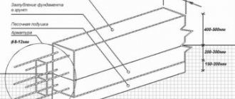
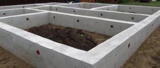
The basis of a building is the foundation. A drawing will help you calculate the underground and above-ground parts of the foundation and select materials for the foundation itself and waterproofing. It will also be the main document for builders during the construction of the building as a whole and its individual elements.
In addition to the drawing, an estimated cost is calculated, which includes the cost of materials and work.
Floor covering diagram
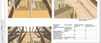
Methods for making floors between floors, as well as attic spaces, are shown in the drawings. Dimensions, material consumption, main structural elements. Depending on the type of materials used, the method of making the floors is determined.
Stairs
They can be installed both inside and outside the building. The drawings show the size, “step” of the staircase and indicate the features of its installation, as well as the use of materials.
Ventilation ducts and chimneys
Chimneys and ventilation ducts, which are also displayed on the facade of the house. The ventilation system must be designed in such a way as to ensure effective air exchange in the premises. Chimneys are included in the heating system.
Drawing the facade
When drawing building facades, all constructions must be carried out in the following sequence:
External contour of the building
Drawing of coordination axes, designation of the general outline of the structure, as well as (if any) its protruding parts.
Architectural elements of the facade
Drawing of door and window openings, slabs of canopies over entrances, balconies, cornices, as well as other existing façade elements.
Development of the facade of the house
Applying doors, window frames, balcony railings located on the roof of chimneys and ventilation pipes, placing elevation signs.
Development of building facades
Next, they check whether the facade corresponds to the sections and the plan, and carry out its final outline. If the buildings are large-block or panel, then seams are drawn between the blocks and panels.
To depict visible contours in facade drawings, a solid thin line is used. To draw the ground contour line, you can use a thick line extending beyond the boundaries of the facade.
Source
Frame houses
The planning and design of frame houses have some features. This is the use of materials, the use of a standard plan. And the main thing that distinguishes frame houses is the speed of their construction.
Drawings of the future building will be useful not only during the construction of the building itself, but also for submitting them to state or municipal authorities that carry out construction supervision and issue building permits. They may also be needed to present them to the bank when obtaining a mortgage.
Functionality of specialized programs
A wide selection of software is freely available, focused on solving various problems and designed for both ordinary users and the professional level. Some programs are highly specialized and “tailored” rather for renovating an apartment or house with an emphasis on design, others, on working out the layout and arranging furniture, and still others, on visualizing architecture. There is no universal amateur builder in which you can create a full-fledged house project, from the first to the last nail, but programs with extended functionality are quite enough “for yourself.” Modern software has a large number of possibilities.
If a couple of years ago there were still difficulties with Russification, today builders use Russian to design private houses. Conventionally, almost all construction kits designed for installation are professional software - they came from abroad, and there is no concept of self-builds and home-made house designs there at all. But in fact, they are already adapted to the amateur level, which, coupled with educational videos, makes them accessible even to beginners. However, the most valuable resource will have to be spent.
If you have never dealt with house design and drawings before, then any, even the simplest program will take time to master and understand - it’s not like drawing in Paint.
How to make window openings on a house plan in AutoCAD (algorithm)
To create window openings in AutoCAD, I used the following algorithm (you can use any convenient method for creating window openings on the plan):
Call the Line command in AutoCAD and draw the first wall of the window opening.
Select the segment and activate the handle. Select the “Move” option from the context menu for editing objects in AutoCAD using handles. Next, to make a copy of it when moving a segment a specified distance, select the “Copy” option. Copy the segment to a distance of 910 mm, i.e. the width of the window opening. To track perpendicular angles and polar angles in AutoCAD, you will need polar snapping or ORTO mode.
Using the “Copy” and “Rotate” commands in AutoCAD, copy the window openings and place them according to the drawing of the house plan.
First floor project
We draw the vestibule and the hallway on the sketch - and from there there will be transitions to the kitchen and other rooms. The location of the premises must take into account the following points:
Step 2: draw all the rooms and premises of the first floor with the required size
After this, we arrange and plan all the doors of our house
Step 3: designing doors on the first floor
Then windows, taking into account the desired lighting of the rooms and your budget
Step 4: designing windows on the first floor
As a result, we get this first floor:
This is how the 3D model of the first floor turned out
Measuring and determining the size (width) of window openings on a house plan in AutoCAD
Use the “Distance” tool on the classic “Details” toolbar, or from the “Utilities” toolbar on the “Home” tab of the tool ribbon, thereby calling the “Dist” command in AutoCAD. Measure the width of the window opening. Its width was 932 mm.
Below is a picture of “Width of window openings for residential premises for external walls”. According to GOST data, the sizes of window openings for the plan of our cottage are 910 mm, 1210 mm, 2110 mm.
What are window trims used for?
The platband is made of a material that is intended to frame the window. The thickness of the platband is about 3-4 cm, so it will stick out a little to create the aesthetics of the facade. Also, such a strip can close all sorts of gaps that form between the window frame and the plane of the window. The casing prevents precipitation, temperature and pressure from entering the room. With the help of this element it is possible to reduce the noise level in the house and prevent the development of mold and mildew in the window area. The casing is also installed for thermal insulation, so they retain heat inside the room.
Source
Window sashes
If a binding is not hung on the binding shown on the construction drawing, then the top of the corresponding sign should be directed towards it. As for architectural drawings that depict window units, they must be part of the design documentation or the documentation of the order for the manufacture of a particular product.
On those construction drawings that are made on a scale of 1: 200 or less, quarters are not shown.
| Image | Name |
| Binding hung from the side and opened inward | |
| Side hanging and outward opening | |
| Binding suspended from below and opened inward | |
| Bottom hung and outward opening | |
| Top hanging and inward opening | |
| Top hanging and outward opening | |
| The suspension is located horizontally in the middle | |
| The suspension is located vertically in the middle | |
| Sliding window sash | |
| Window casement with riser | |
| Blind binding | |
| Side or bottom suspension and inward opening |
Window sash
A window frame is a building structure necessary to strengthen and divide the glazing field and decorate it. It consists of several elements: transoms, windows, sashes. The window frame, in turn, together with the window frame, makes up the window block.
Window units are designed in such a way that during their operation it is possible to replace glass, double-glazed windows, sealing gaskets, window devices, while maintaining the integrity of these parts.
All opening elements of windows installed in residential buildings must open only to the inside of the premises. For individual structures (for example, windows that are installed in the premises of the first floors of buildings or overlook balconies), modern standards, building codes and regulations provide for the possibility of opening outward.
In order to ensure ventilation of the room, in the windows with which they are equipped, either transoms, or casement windows, or regular windows are installed, or special supply valves are installed in them. Transoms can be either openable or blind; they are usually mounted above the sashes, in the upper parts of window frames. To secure an openable transom in the window frame, a horizontal impost is used.
If the box is wide enough, then a vertical impost is installed in it so that the edges of the vertical bars of the sashes adjoin it. Based on the number of sashes in one row, windows are divided into:
- Single leaf
- Bivalve
- Multi-leaf
As for the design of window frames, they are:
- Single
- Paired
- Separate
- Separately paired
In window blocks with paired sashes there are two of them: external and internal. They are connected to each other, and the inner one, in addition, is hung on the box using hinges. Thus, the sashes, connected to each other by fastening elements, form a binding with a fairly high rigidity.
TYPE 8 Window trims decorative design of windows on the facade of a building photo, drawing
Decorative design of windows on the facade of a building is an important issue that deserves detailed consideration. The exterior of a house can be compared to a face, and the windows reflect its internal state, the owner’s attitude towards personal property. It is possible to make a building more attractive to others with the help of platbands. They are the ones who can transform windows, give them a new style and, moreover, protect them from the influence of external factors. The main thing is to choose high-quality window frames and their design.
Approval of the project to begin construction
The need to adjust the project. Even if you yourself were able to depict the house of your dreams on paper, you will still need to consult with specialists before starting construction of the house - the opinion of a competent foreman or architect will not be superfluous. At a minimum, the following points will need to be agreed upon:
It is necessary to understand that all the above issues are not an artistic or architectural part of the project. These are all the most routine issues, a competent approach to solving which is provided only by professionals in their field. As a last resort, any oversight in independently drawing up a house project, which was made by a person who does not have a specialized education, can be corrected by a competent foreman who understands the practical side of any idea much better. Although even if the project is drawn up by professional architects, purely practical shortcomings cannot be ruled out.
Independent work on a house project and its advantages
You can create the design of your house yourself - in order to develop drawings of the relative position of certain rooms, as well as determine the place of the house on the site, you do not need special knowledge. A competent and responsible approach to business will ensure the success of your event. However, in terms of communications, it will be necessary to consult with professionals. This way you can properly plan a house that will serve you faithfully.
Source
Develop a project or order?
An almost eternal question, to which there will always be two answers.
I drew it myself, put up the box myself. I think I'm doing everything right.
I am not an architect or a designer - therefore, everything I draw will be crude and require rework. I consider design a very important part of construction, which needs to be done for a fee and by professionals. And to visually express your wishes, the best is “Sweet Home 3D”, you can even do it online. No more is needed. I mastered it in 2 hours with all the nuances - it’s a pleasure to draw, simple and fast.
Which option is correct depends on specific conditions; there are also two incentives for both “for” and “against”.
I drew the house myself in Archikad. Only because of austerity, because... I'm building myself. Ideally, it would be to get a finished project, with all the subtleties. And you wouldn’t have to rack your brains about how and where to lay the pipe, where to lay the cable, whether the partition or beam or slab will withstand the PC, etc. little things that take a lot of time to think about. One good thing is that the work is such that there is enough time.
Source
Designation (image) of windows on a house plan in AutoCAD, line thickness
We built window openings on the house plan in AutoCAD, and also made a symbol for the glazing of window openings, but the designation (image) of windows on the house plan does not end there. The fact is that you also need to observe the thickness of the lines on the window designation on the plan!
In order not to redraw the walls that run directly through the window openings, break them at a special point with the “Break at point” tool of the “Break” command in AutoCAD.
To conveniently change the thickness of wall lines from thick to solid thin, passing through window openings, use the “Copy Properties” tool in AutoCAD.
See the video tutorial below for more details.
AutoCAD commands and tools used to create window openings and windows on the house (cottage) plan:
Window sashes
If a binding is not hung on the binding shown on the construction drawing, then the top of the corresponding sign should be directed towards it. As for architectural drawings that depict window units, they must be part of the design documentation or the documentation of the order for the manufacture of a particular product.
On those construction drawings that are made on a scale of 1: 200 or less, quarters are not shown.
| Image | Name |
| Binding hung from the side and opened inward | |
| Side hanging and outward opening | |
| Binding suspended from below and opened inward | |
| Bottom hung and outward opening | |
| Top hanging and inward opening | |
| Top hanging and outward opening | |
| The suspension is located horizontally in the middle | |
| The suspension is located vertically in the middle | |
| Sliding window sash | |
| Window casement with riser | |
| Blind binding | |
| Side or bottom suspension and inward opening |

