One of the alternative sources of heating a house or apartment is an electric underfloor heating system. Due to ease of installation and ease of use, cable flooring is rightfully one of the most popular among consumers.
Before considering how to make an electric heated floor, we suggest that you familiarize yourself with the advantages and disadvantages that this system contains.
Electric heated floor - advantages and disadvantages
Pros:
- the ability to be used both as the main and as an additional source of heating for housing;
- uniform heating of the entire area of the room;
- unlimited installation locations. Availability for installation in both living rooms and offices;
- compatibility with most floor coverings (laminated boards, ceramic tiles, linoleum);
- the ability to adjust the temperature regime - both throughout the apartment and separately in each room. The system on/off time is also set at the discretion of the users;
- no need to install additional equipment (as, for example, in the case of a water heated floor);
- relatively simple installation technology;
- aesthetics. The system is installed under the finished floor, this eliminates any restrictions when designing the available space;
- long service life.
Minuses:
- significant cost of using the system. This type of heating can hardly be called economical;
- danger of electric shock. Which puts forward special requirements for the calculation and installation of the heating element in all rooms, and in particular in the bathroom;
- the presence of an electromagnetic field created by the heating element (cable);
- The use of natural wooden flooring is excluded (laying under parquet or floorboards is not possible), because under the influence of temperature changes, the wood will dry out, as a result, cracks and creaks of the floor will appear;
- reducing the height of the room by installing a subfloor with a heating system;
- additional requirements for the power of existing electrical wiring.
Professionals and users who have installed electric heated floors themselves note that compliance with installation requirements and competent design make it possible to eliminate most of the listed disadvantages.
What affects energy consumption with cable floor heating
Factors affecting the energy consumption of an electric heated floor system
- climatic zone in which the house is built (private or multi-apartment);
- volume of the room (area);
- type of floor (type of floor covering);
- level of thermal insulation of the room (degree of fatigue);
- the state of the warm circuit (windows, doors) and the level of heat loss through them;
- purpose of the premises (living room, industrial facility);
- purpose and period of operation. Is the electric floor used as a primary or secondary heating system? Constantly or periodically;
- the degree of heat perception by people living in the room.
According to reviews from those who already use electric heated floors - when using the system as the main heat source - its power is 170-200 W/sq.m., as an additional one - 100-150 W/sq.m.
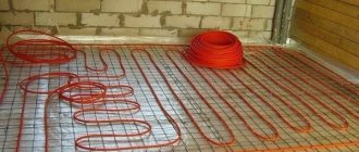
Surface preparation
First step. We dismantle the old floor covering and screed. When laying a film heated floor, the old screed, if it is in good condition, does not need to be dismantled. If you install a cable system, you will have to get rid of the tie. Thoroughly clean the surface from dust and dirt.
Dismantling the floor screed
Second step. We lay a layer of waterproofing material. Traditionally, polyethylene film is used, but you can choose other insulation if you wish. It is important that the moisture-proof material extends approximately 100-120 mm onto the walls.
Floor waterproofing
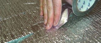
Third step. We attach a damper tape to the wall along the perimeter of the base. Thanks to it, it will be possible to compensate for the thermal expansion of the system during heating. We carefully trim off the excess waterproofing and damper tape.
Film and damper tape
Fourth step. We lay a thermal insulation layer. Thanks to it, loss of thermal energy through the base will be eliminated. Choose insulation taking into account the location of the room, the type of base and the intended purpose of the heating system.
Floor insulation with polystyrene foam
If you plan to use the system as an addition to the main heating, thermal insulation can be done using polyethylene foam equipped with a reflective foil layer. Additionally, the material will take on the function of a substrate for a heated floor.
Foamed polyethylene in a heated floor system
If there is a heated room on the lower floor, it is best to install thermal insulation using expanded polystyrene sheets. The thickness of the material is 2-5 cm. Another insulator with a similar thickness will do.
When installing a heating system in a previously unheated room, for example, on a veranda or balcony, the thermal insulation layer must be more thorough. For example, 10 cm insulation with polystyrene foam or mineral wool of similar thickness is suitable.
Insulating the loggia floor with mineral wool
Fifth step. We lay a reinforcing mesh on the insulation. If desired, you can add microfiber and plasticizer to the screed solution. This improvement in the composition will make it possible to do without additional reinforcement.
A reinforcing mesh is laid on top of the insulation and beacons are installed for pouring the screed
Installation of electric heated floors - errors
Here are a few typical mistakes that, as evidenced by reviews from home craftsmen, are very common:
- buying extra material. The error is due to the fact that in the calculations the user is guided by the total area of the room, and not by the area that will serve as the basis for the heated floor. The calculations do not take into account the area occupied by furniture and heavy household appliances (refrigerator, washing machine);
- The cable used in the heating mat must not be cut. You need to choose a laying pattern in order to use the mat completely. It is better to leave part of the floor surface uncovered;
- You cannot turn on the floor heating system until the screed is completely dry, because this can lead to uneven drying of the layer and the appearance of cracks and voids.
- The cable must not be laid on an unprepared surface. It is better to treat the surface of the subfloor with a primer to eliminate dust, which can cause air pockets to form around the cable and cause it to overheat;
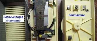
- the temperature sensor is placed in a corrugation, so it can be dismantled and repaired if it fails;
- Resistance measurement is an important stage of pre-operation testing of an electric floor; it should not be ignored. In case of significant deviations, you need to make a decision to correct the situation on your own or involve professionals;
- The cable laying diagram will be useful when moving furniture and performing repair or maintenance work. The easiest way is to photograph the installed floor before pouring the screed.
Electric heated floors are easy to use, reliable (if you choose good components and install them correctly) and will last a long time.
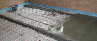
Fill the screed and lay the finishing coating
Filling the screed
The screed is best made from a special ready-made mixture. The packaging of this composition will indicate that it is designed specifically for use in combination with heated floors. Prepare the mixture according to the instructions. Sufficient layer thickness is 40-50 mm.
Approximate table for calculating the power and length of the heating cable
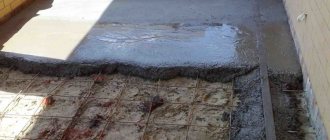
Spread the mixture evenly over the surface using a spatula. Make sure that there are no air pockets under the cable body. Because of them, the quality of heating will noticeably deteriorate. Let the screed dry completely.
Summary table of requirements for specific and linear power depending on the purpose of the room and type of heating
Important: infrared and heated floors require different “holding” times after installation. You can use the film floor after 2-3 days (if the screed has not been poured). The cable system must be allowed to settle for 3-4 weeks.
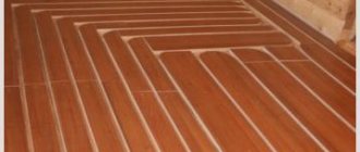
We lay the finishing coating in accordance with the installation technology of the selected material. Most often, tiles and laminate are laid on top of a warm floor. You can also lay parquet and even linoleum. If desired, you can use another coating. Focus on your preferences, the interior of the room and your available budget.
Approximate values of energy that should be emitted by a heated floor in domestic premises
Good luck!
Prices for various types of screeds and self-leveling floors
Screeds and self-leveling floors
Some brands of power cables
VVG. A power cable with multi-core copper wires, sealed and durable PVC insulation, is laid to connect distribution boards over the air on cables, along walls, underground and cable ducts in various structures. It is very flexible and suitable for routes with a lot of turns and bends.
AVVG. This is practically the same cable as VVG, but the letter “A” means that the conductors are made of aluminum wire; without the letter, the default means that the wires are copper.
AVVG cable structure with solid current-carrying cores
Two letters “B” mean that each core and outer sheath are covered with a vinyl layer of insulation, “G” - the bare cable does not have additional armored protection.
Specifications:
| Brand | Number of cores | Section, mm2 |
| AVVG | 1…4 (round) | 1,5… 240 |
| AVVG | 3-4 (sector) | 70… 240 |
AVK. The cable has a coaxial design, in the center there is a monolithic aluminum core, then an insulating vinyl layer, which is shielded by thin aluminum wires arranged in a row around the diameter along the entire length. The outer shell is made of durable sealed plastic.
AVK cable structure
The cable is very practical; it can be laid from overhead lines with voltages up to 380V, underground from substations to distribution boards of buildings. One of its main advantages is considered to eliminate the possibility of unauthorized connection on uncontrolled sections of the route.
SIP-4. A special feature of this cable is its self-supporting design, which allows the cable to be placed on overhead lines without cable suspension.
Colored marking stripes on the insulation of SIP cable cores
This quality makes it universal; it can be laid along the walls of buildings, underground and cable ducts, in rooms with high humidity. It has reliable sealed PVC insulation on each wire with a multi-core structure.
Main parameters of SIP-4:
| Number and cross-section of cores, mm2 | outer Ø mm | SIP cable weight, kg/km |
| 1x16 | 7.5 | 70 |
| 1x25 | 8.5 | 100 |
| 2x16 | 15.5 | 140 |
| 2x25 | 17.5 | 200 |
| 3x16 | 16.5 | 205 |
| 3x25 | 18.5 | 290 |
| 4x16 | 18.5 | 280 |
| 4x25 | 21.0 | 395 |
For the supply from the overhead line to the control panel of a residential building, 3x16 or 4x16 cables are usually used; the number of wires in the cable and the cross-section are quite sufficient for the power consumed in domestic conditions.
AVBbShv/VBBShv. The design feature of this cable is the presence of an armored layer; two steel tapes are wound onto the surface of the cable so that the top one covers the gaps between the turns of the bottom tape. The cable is fully armored, in addition there is PVC insulation on each core and a common sheath.
Cable structure AVBbShv/VBBShv
Explanation of markings:
- A - aluminum conductors can be monolithic or twisted from individual wires; the absence of this letter by default implies a copper alloy of wires.
- B – vinyl insulation of wires;
- BB – armored steel belts;
- Shv – PVC hose as an outer insulating sheath.
- Shv ng - may indicate that the insulation is made of non-combustible materials.
The cable structure can have from 1 to 5 cores of the same or different cross-sections; usually the yellow-green or neutral blue ground wire is made of a smaller diameter. To connect private houses, do not use cables with a wire cross-section of more than 16mm2. At industrial facilities, the cross-section can reach 300 mm2 or more.
Specifications:
| Number of cores, mm2 | Cable outer diameter, mm | Weight of 1 km cable, kg | |||
| AVBbShv | AVBbShv ng | ||||
| ~ 660 V | ~1000 V | ~660 V | ~1000 V | ~660 V | ~1000 V |
| 3x4 | 15.5 | 17 | 380 | 435 | 395 | 450 |
| 3x6 | 16.5 | 18 | 435 | 495 | 450 | 510 |
| 3x10 | 19.0 | 19.5 | 575 | 595 | 595 | 615 |
| 3x16 | 21.5 | 22.0 | 720 | 744 | 745 | 770 |
| 3x25 | 25 | 25.5 | 955 | 980 | 985 | 1010 |
| 3x35 | 27.0 | 27.5 | 1135 | 1160 | 1170 | 1200 |
| 3x50 | 30.5 | 31.0 | 1445 | 1480 | 1490 | 1525 |
| 3x4+1x2.5 | 16.5 | — | 420 | — | 435 | — |
| 3x6+1x2.5 | 17.5 | — | 490 | — | 505 | — |
| 3x6+1x4 | 17.5 | 19.0 | 370 | 555 | 390 | 570 |
| 3x10+1x4 | 30 | — | 675 | — | 695 |
A cable with armored protection can be laid in an environment with high humidity and underground, but this does not exclude the possibility of using it in other more favorable conditions.
Which wires are not suitable?
There are product options that are strictly prohibited from being used for laying electrical networks, even in the most extreme cases. These include the following types of products.
Product #1 - PVS wire
Copper connection element having a PVC sheath and insulation. It has a stranded design with 2-5 conductors with a cross-section of 0.75-10 sq. mm.
The wire, designed for a voltage rating of 0.38 kW, can be used to connect household electrical appliances to the power grid and for making extension cords.
PVA is not suitable for laying wiring for the following reasons:
- It has a multi-wire core structure, so it requires tinning and soldering to connect the ends, which requires a lot of time and a lot of experience.
- The product creates a fire hazard: the wire strands cause the cable to heat up more, causing the insulation to wear out faster, which can lead to a short circuit.
- PVA cannot be laid in a bundle, whereas almost all cable models are suitable for this. Due to the fact that the wiring lines must be at a certain distance from each other, you will have to make grooves in the wall for each of them.
Thus, even the low price of such wires cannot compensate for the high installation costs, and the quality of the installed electrical network will not be too high.
Product #2 - SHVVP, PVVP wires
Cords or cables having single or multi-wire copper cores can be used to connect household appliances and electrical equipment.
However, they are not suitable for fixed electrical communications because these products do not have non-combustible insulation.
Although a flat cord with polyvinyl chloride sheaths (SHVVP) is not recommended for laying electrical networks, it is quite suitable for organizing low-current lighting up to 24V, namely for laying wiring from a transformer to LEDs
In addition, the service life of SHVVP and VPPV is quite short, and the multi-core design requires processing of the ends and soldering during installation.
It is also worth mentioning PUNP (universal flat wire), which was banned for laying electrical networks in apartments back in 2007.
This outdated product has poor insulation and low power, making it unable to withstand modern loads
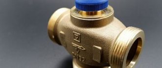
Return line
Warm floor → 35 °C → Check valve with outlet → 35 °C → Boiler
To install the circuit, use one of the types of three-way valves:
- With thermostat function. Adjustment of the pressure of mixed flows plus maintaining the set temperature.
- With remote sensor. Adjusting the intensity of hot water supply.
Automation controls the temperature of the water supply to the VTP. According to the specified parameters, the thermoelectric servo drive closes and opens the valves of the distribution manifold. It blocks the passage of hot coolant, and when the water in the system cools, it raises its rod, mixing the flows.
Water heated floors are suitable for connection to a heating system only in private housing. In city apartments or high-rise buildings, such installation is impossible for technical reasons.
The maximum effect from HTP is achieved with the help of autonomous heating sources. The best option is a gas boiler, which heats the circulating coolant to 45–50 °C.
If the system is correctly connected according to the most effective scheme for specific rooms, the heated floor will last for a long 30–50 years.
Application of thermal insulation
Electric floor heating elements are mounted on an insulated surface (gypsum fiber board, polystyrene or PVC boards, etc.).
It is desirable that the insulator have a foil surface. It should be located in the border zone, between the cement base and the self-leveling screed.
It should be noted that this installation option is not durable and reliable, but, nevertheless, its popularity is quite high, since it is easy to install.
Installation of heating sections
When the cable has not yet been unwound, you will need to measure its resistance level. After this, enter the resulting value into the warranty card and check whether it matches that specified by the manufacturer. In this case, the possible deviation is approximately 10%, but if the values diverge by a larger number, then it is better to replace the cable.
If everything is in order with this, then we proceed to the next stage. Namely: you need to insert the cold end of the heating cable into the corrugation, and then put it in the groove, which we have already prepared. Then attach the beginning of the cable and the connecting sleeve to the mounting tape. Cable laying will need to start from the same place. It is important that the coupling is completely covered by the concrete screed. In addition, you need to ensure that there is no crossing or contact of the cable laying lines and strictly follow the laying step.
In the place where the heating cable makes a loop and bends, the radius of this bend must be at least 5 centimeters, otherwise the cable may be damaged. The coupling for the two-core cable is also fixed to the mounting tape, and it must be completely covered with a concrete screed. If a single-core cable is used, when drawing up the installation diagram, remember that both ends of the cable must be connected to the thermostat.
Counting the number and power of mats
First you need to decide on the power of the mats, and then calculate their number. Since tiles are installed mainly in the bathroom and kitchen, it is worth taking the indicators for these rooms as a guide:
- average power for the kitchen – 110-130 W/m2;
- the average power for a bath, shower and toilet is 120-150 W/m2.
These indicators are relevant only if the heated floor is installed as an auxiliary heating system. If the electric floor is designed to thoroughly heat a kitchen or bathroom, the power of one mat should be at least 140-180 W/m2.
Next, we calculate the usable area of the room - multiply the length of the room by the width and subtract the area that household appliances will occupy.
Now you can calculate the number of mats - divide the usable area by the area of one element of the selected power.
Laying infrared film
Finally, let’s look at how to install infrared-type heated floors.
The installation operation is not particularly difficult, but before installation it is necessary to carry out preparatory work.
It will be necessary to lay a thermal insulation layer on the floor surface. In this case, the layers of thermal insulation are secured to each other with mounting tape.
Next, an infrared film is spread on the surface of the thermal insulation.
If necessary, pieces are cut off; this should be done only in the places indicated on the film.
In this case, a distance of 4-5 cm must be maintained between the two strips of film.
Also, the film does not need to be placed in furniture locations; it should not come close to the walls or other heating elements of the house.
Connection diagram
The installation of heated floor systems depends on parameters such as the specifics of the premises and the type of heating elements used. The most common:
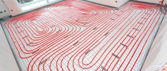
- resistive cable is a reliably insulated cable with high resistivity that generates heat when electric current passes;
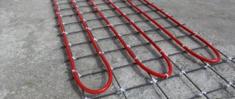
- thermomat - differs from the previous one only in that the cable is already mounted on a special nylon mesh;
- film flooring is a thin film of a special composition with built-in carbon fiber strips, which serve as a heating element.
In any embodiment, they have three main components:
- heating, as already noted;
- intermediate, consisting of a coupling through which the cold end of the heating elements enters the installation box - it is installed on the wall;
- control, the main components of which are a temperature sensor installed through a corrugated tube and a thermostat.