Supply and exhaust ventilation works by consuming and processing outside air. In conditions of negative temperatures and long winters, the air flows must be heated, because if you let them in directly, the microclimate inside the building will become unsuitable for humans. The supply air is heated by a heater. The efficiency of the ventilation system directly depends on it. Therefore, the piping of the supply air heater must be carried out in compliance with all norms and rules and only with high-quality materials. The technical part is being developed in the project.
Variants of typical solutions for piping steam equipment
Today, various equipment is used to install steam heaters. Depending on what it will be, completely different patterns and piping knots are used.
Special heater steam piping system for condensate removal:
Typical steam equipment piping.
- 3 shut-off valves, which are installed at the inlet, outlet and in the middle;
- thermodynamic diverter, which has a valve and a built-in filter to protect the system;
- sight glass for periodic inspection;
- check valve;
- special drain pipe for condensate;
- condensate drain;
- condensate line
The minimum length of the common condensate drainage unit for a steam heater is 1 m.
Collector piping.
If it is necessary to connect several points, then the use of a steam manifold with drainage is required. The diagram includes the following nodes:
- 3 shut-off valves (at the beginning, end and middle for adjustment);
- pressure gauge for pressure control;
- viewing window for system monitoring;
- float drain for condensate, which has a built-in filter and valve to protect the system from contamination;
- check valve
Steam reduction unit with pilot control.
Such a unit is necessary for generating steam; it includes:
Steam reduction unit.
- shut-off valves;
- several pressure gauges to control pressure in different areas;
- filters that are designed to work for 3-9 hours;
- pressure reducing valves designed to control the system;
- check valve;
- viewing window for monitoring the system and its condition;
- blast safety valve;
- special drain pan for collecting condensate;
- conclusion;
- drain pipe.
The length for such a system unit cannot be less than 10 diameters of the steam line; in some cases, a built-in impulse tube is provided.
Options for adjusting temperature during heating process
Diagram of a heater piping unit with a three-way valve
The heating control process is of two types: qualitative and quantitative.
The use of quantitative heating control is not always advisable, since the amount of coolant constantly changes during operation.
High-quality heating regulation implies operation of the heater using the same volume of coolant.
There are several advantages of the high-quality heating principle:
- stable linearity of the process is ensured in any position of the control valve;
- freezing of the unit can be prevented or reduced by ensuring a constant flow of water;
- if there is a special pump and a three-way valve, then in this case the qualitative principle of heating control is used.
Heater steam distribution unit
The steam heater must be connected with a special distribution unit, that is, up to the supply point. This node includes:
Figure 2. Components for piping heaters of supply air systems.
- a special cyclone filter with condensate drainage, which also provides protection against contamination;
- pressure gauge to monitor the operation of the system;
- shut-off valves;
- safety valves;
- pressure regulators that provide pilot control;
- check valves;
- pressure reducing valves;
- special condensate discharges into the atmosphere.
The length of each steam supply section cannot be less than 10 steam line diameters. For each outlet, a shut-off valve and a pressure gauge for each section are installed at the steam supply point. The diagram of the strapping unit is shown in Fig. 2.
Automated air heating in supply ventilation
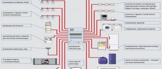
Options for constructing round and rectangular ventilation shafts - the system is automated
- The operation of the equipment is controlled using a control panel (CP). The user presets the mode for regulating the supply air flow and temperature.
- Using a timer, the heated ventilation system automatically turns on and off.
- Equipment that provides heating can be connected to an exhaust fan.
- Heaters are equipped with a thermostat that prevents fire.
- A pressure gauge is installed in the ventilation system to monitor pressure differences.
- A shut-off valve is installed on the supply ventilation pipe; it is designed to block the entry of incoming wind masses.
(no votes yet)
Heater connection diagrams
The heater has one task - heating the incoming air masses, with the ability to adjust the temperature of the coolant. There are several installation schemes:
- One ventilation circuit, one heater. The simplest scheme is when a single copy of the device is installed at the entrance or any other point of the ventilation duct. Suitable for seasonal heating. There is no backup heat source.
- Two ventilation circuits, several heaters. A more complex scheme, with numerous strapping nodes. The first circuit with its channel heating elements operates in the autumn-winter period, the second - in the summer. The double scheme is applicable for large buildings that require heating all year round. Allows you to safely pass through peak frosts by turning on both heating circuits.
What it is?
The heater for supply ventilation is made in the form of a heat exchanger, in which the air masses coming from the street are heated to the desired temperature. The device is a separate device that is either installed into the system independently or is already built into the ventilation unit. This depends on the design features of the ventilation unit, and is determined by the technical capabilities of installation and the personal preferences of the consumer.
In prefabricated modular systems, all elements are purchased separately and then connected into a single ventilation network, while in monoblock installations the elements are already installed and adjusted. In addition to heaters, the ventilation unit includes a filtration and humidification system, which allows you to obtain air at the entrance to the room that meets strict sanitary and hygienic standards. Some modern systems are additionally equipped with devices for disinfection and ionization of air flows.
Harness knots
They supply coolant to the heater and provide control over the temperature and pressure in the system.
Composition of the node diagram
Scheme of operation using the example of a water heater.
The classic scheme of the piping unit includes:
- Circulation pump.
- Compressor-condensing unit (KKB). It is used in piping cooling systems as an external unit. Connects to coolers of supply ventilation units or duct air conditioners.
- Devices for monitoring basic parameters: temperature and pressure.
- Shut-off valves.
- Bypass.
- Filter for cleaning incoming air masses.
- Automatic valve. There are two-way and three-way.
- Pipes and fittings.
The piping unit can be connected to the system using a rigid or flexible connection:
- Hard eyeliner. A simple connection option using metal pipes. It is practiced when the installation location of the heater is known and prepared in advance.
- Flexible eyeliner. A more complex connection option. Flexible corrugated hoses are used. It is practiced when the heater is installed in an unprepared place.
Heating adjustment
Designers distinguish two ways to regulate the temperature of a duct heater: quantitative and qualitative.
- Quantitative. An outdated method of adjustment. The temperature is directly dependent on the volume of the coolant; for this purpose, a two-way valve is installed in the piping system. The method is recognized as not rational, since the volume of coolant consumed is constantly “jumping”.
- Qualitative. More efficient way. At any position of the control valve, the coolant is consumed according to a linear principle. Linearity is ensured by a three-way stem valve and pump. The pump cuts directly into the heater circuit, its rotor rotates in a liquid medium. There is no need for seals and leaks are completely eliminated.
A three-way valve with a stem is installed at the entry point. If it is closed, then water circulates in a closed circuit. In the open state, the possibility of recirculation is excluded, since the backflow is prevented by the check valve.
Classification
To create an optimal microclimate in the building, a calorific heating system is used, that is, forced heating using equipment that is installed in air ducts.
Depending on what coolant is used, there are 4 types of heaters:
- Steam - used most often in industrial enterprises where steam production is provided for by technological processes.
- Electric - this option is the easiest to install (you only need a power source to heat the built-in heating elements), but it requires a lot of electricity consumption. The use of an electric heater is considered appropriate only in facilities whose area does not exceed 150 m²
- Water - this type of heater operates on the basis of hot water and is installed in ventilation systems with a rectangular or round cross-section in areas over 150 m². This type of heating is reliable, practical, easy to maintain and inexpensive.
A special feature of the heater is that the composition of the air flow coming from the street should not be sticky, fibrous, or contain solid particles. Permissible dust content is no more than 0.5 mg/m³. Minimum intake air temperature -20 °C.
When choosing a heater, the following factors are taken into account:
- room area;
- weather conditions in a given climate zone;
- ventilation power.
The heater is installed in the inside of the ventilation shaft, so it must correspond to its parameters (configuration and size).
If the performance is low, the device will not be able to warm up the air masses.
If it is not possible to install a heater with the required parameters, then several mechanisms with lower power are mounted in series.
Types of thermal energy consumption systems
There may be several such systems compatible with the heater. Let's look briefly at each.
Ventilation system
It is characterized by the fact that the maximum temperature of the coolant is directly influenced by the technical parameters of the existing equipment. The problem with regards to how to choose the right piping unit is the need to protect the heater from possible freezing. In winter, when the air is supplied at sub-zero temperatures, the temperature of the coolant cannot be reduced or the energy consumption lower than what the system requires.
Radiator heating
In this case, the coolant temperature is strictly limited. For single-pipe structures it is 105 degrees, for two-pipe structures it is 95 degrees. But the temperature of the carrier can decrease indefinitely, until the operation stops altogether, which distinguishes heating from a ventilation system. Here, all elements are in direct contact with the air in the building, and due to the fact that it also has heat-storing characteristics, the building cools quite slowly. In this case, the time period during which a decrease in temperature is possible is established for each individual case.
Underfloor heating
The heat consumption here is the same as in the previous version. The only difference can be considered that the temperature of the coolant (maximum) is limited. In most cases this is no more than 50 degrees.
Thermal curtain
The heater piping for thermal curtains differs significantly from all previous options, so we will consider it in more detail. First of all, this relates to the peculiarities of the operation of the thermal curtain itself: almost all the time the curtain “rests”, waits, but its working time often does not exceed two to three minutes. Moreover, the installation site is always located far from the heating source. In most cases, this is a place under the ceiling, and there, accordingly, hypothermia often occurs, as well as drafts. Below is a diagram with adjustment elements that are suitable for this case.
The system is equipped with special ball joints necessary to disconnect it from the described curtain or from the thermal route. There is also a coarsely cleanable filter that protects the device; an adjustment valve that prevents the entry of solid particles, which, in turn, can extremely negatively affect the performance of the system in general. There are two more valves:
- Regulating-shut-off.
- Regulating, equipped with a special drive.
Each of them is designed to provide maximum fluid flow in operating mode, and minimum flow when “inactive”. In order for the valve drives of such a piping intended for thermal curtains to be provided with proper power, a single-phase voltage of 220 volts should be connected.
Finally, all the elements that make up the heater piping in this case are necessary not only to regulate the temperature in the building, but to protect the device itself from temperature changes and pressure “jumps” that often occur in the heating supply network. If you install mixer blocks, the heating circuit will reach the operating mode that is necessary for the controlled parameters.
Note! Ventilation works more efficiently in this regard, since less energy is consumed.
How to make exhaust ventilation with your own hands
Installing exhaust ventilation yourself is a completely feasible idea. First, they make calculations and select components, after which they begin assembly. For residential premises, a local hood in the kitchen is popular. It can be installed not only by a specialist, but also by the apartment owners on their own. Air and steam will be removed forcibly through air ducts, of which the flexible version is easy to install. In this case, control is carried out manually using a switch.
A simple diagram for installing a kitchen hood
The hood is placed above the stove. It is preferable to take the outlet out to the outside. Otherwise, reverse draft is possible from the natural ventilation of the building. Installation instructions and a list of components can be found in our article on installing a kitchen hood.
Water heater calculation
Calculation of the heater power required to heat a particular room is carried out taking into account such data as:
- The volume (mass) of supply air that needs to be heated.
- Initial (external) temperature of air masses.
- The target temperature to which the air must be heated before being supplied to the room.
- Temperature regime of the coolant.
The heater is calculated based on the heating surface area and the required power. Each operation has its own formula. The heater power can be calculated only taking into account real data in specific conditions, among which the most important are:
- connection method (to the central heating network or boiler room);
- strapping method.
Calculation of heater power
Qt – heater heat power, W; L – air flow, m³/hour ρair – air density. The density of dry air at 15 °C at sea level is 1.225 kg/m³; air – specific heat capacity of air equal to 1 kJ/(kg∙K)=0.24 kcal/(kg∙°C); tin – air temperature at the outlet of the heater, °C; tnar – outside air temperature, °C (air temperature of the coldest five-day period with a probability of 0.92 according to SP 131.13330.2012)
Heater power calculator
Air flow, m³/hour: Air density, kg/m³: Specific heat capacity of air, kJ/(kg × K): Air temperature at the air heater outlet, °C: Outside air temperature, °C:
Coolant consumption per heater
G—water consumption for heating the air heater, kg/h; 3.6 - conversion factor W to kJ/h (to obtain flow rate in kg/h); Qt – heater heat power, W; sv – specific heat capacity of water equal to 4.187 kJ/(kg∙K)=1 kcal/(kg∙°C); tpr – coolant temperature (straight line), °C; trev – coolant temperature (return line), °C.
Coolant flow calculator for heater
Thermal power of the air heater, W: Specific heat capacity, kJ/(kg × K): Coolant temperature (forward line), °C: Coolant temperature (return line), °C:
Air heating process diagram
You can determine the required heater power using special diagrams. The amount of energy required (Joules) to heat 1 kilogram of air is produced using the i-d diagram of moist air. The calculation is made under the condition that the air heating process occurs at d = const (with constant moisture content). Next, taking into account the calculated air flow rate and the conversion of units (J/s to kW), the heater power is determined.
i–d diagram of humid air
To obtain accurate data, you can use online calculators, with which you can find out the power indicator by indicating performance and temperature. Since the performance of the installation may decrease as a result of gradual wear, it is recommended to include a power reserve of 5 to 15% in the calculation.
Methods for organizing air exchange in the house
There are different ways to ensure air exchange in a residential building - from periodically briefly opening doors and windows to installing multifunctional systems for preparing and delivering clean air to each room.
From the point of view of ventilation, a healthy and comfortable atmosphere in the house is formed not only due to the composition of the air. Its temperature, uniformity of distribution and mobility play an important role.
The influx of cool air can create a powerful convection current, which will be perceived by humans as an unpleasant draft. As a result, even at normal temperatures the room will be uncomfortable.
In old brick buildings, ventilation and aeration were provided by special vents left during the construction of a residential building
The ventilation system in the cottage kitchen, made from wooden beams, also seemed as simple as possible. Leaky doorways and window blocks contributed to the continuous circulation of air currents in the house.
All these methods are still used today in small one-story buildings. There is quite enough natural air ventilation there. But if we talk about large and spacious private houses, then it is impossible to do without additionally installed central air conditioners and fans.
Advantages and disadvantages of water heaters
A water heater for fresh air ventilation has significant disadvantages that limit its use in residential premises:
- large dimensions;
- difficulty connecting to a common hot water supply system;
- the need for strict control of the temperature of the coolant in the water supply system.
However, to create a comfortable temperature in large premises (production workshops, greenhouses, shopping centers), the use of such heating systems is the most convenient, efficient, and economical.
The water heater does not load the electrical network, its breakdown will not cause a fire - these factors make the equipment safe to use.
Principle of operation
A fan, a heat exchanger and a convector - this is what a water heating device looks like in general terms.
The operating principle of supply ventilation is as follows:
- The air flow enters special air intake grilles that prevent insects, small objects, birds, and animals from entering the ventilation channels.
- Filters clean the air from contaminants, harmful substances, and dust.
- The heater, using heat supplied from the water main, heats it to the desired temperature.
- The recuperator mixes the newly supplied air with the heated one.
- The fan supplies heated air masses into the room, and the diffuser distributes them evenly over the entire area.
- Sound absorbers reduce the sound power of a running installation.
- If the air supply is cut off, valves are activated to prevent cold air from entering the room.
An example of using a VOLCANO air heater in a tire shop (water temperature +90 ºС)
The heater, which does not have its own heater, consists of two main elements:
- A heat exchanger, the design of which is represented by a system of metal tubes - water coming from the general heating system reaches the required temperature here.
- Built-in fan that disperses heated air flow throughout the entire area.
Basic equipment of heat supply units. Selection and calculation
The heat supply units of air handling units made according to different schemes, as a rule, include identical equipment. Such units differ only in the installation location, the saturation of the reinforcement and the selection method.
When selecting equipment for heat supply units, there are several general rules and recommendations:
- When choosing a particular type of valve, you should carefully check the technical characteristics of both the maximum operating pressure and the maximum temperature.
- It is highly not recommended to purchase ready-made mixing units that are selected based on average conditions without taking into account important parameters such as free pressure drop in the system, type of coolant, flow rate, type of heat source, the need for frequency regulation, and so on.
- The diameter of shut-off valves, as well as check valves and mud traps must be no less than the diameter of the pipelines.
- The diameter of the heating system pipelines is determined as a result of hydraulic calculation based on the calculated (required) coolant flow rate, type of coolant (water or low-freezing liquids) and pipeline material. In no case should the diameter of the heating supply units be selected based on the connecting ports of the heater. It is selected ONLY BY CALCULATION!
Shut-off valves
It is necessary to shut off the water flow in cases of emergency stops of the heating system, for example, to eliminate a leak, to carry out service or inspection work, etc. As shut-off valves, steel or brass ball valves (preferably full bore) or flanged valves are used.
For heat supply units with a pipeline diameter of up to 40 mm inclusive, it is customary to install threaded shut-off valves, and flanged valves over 50 mm.
To facilitate the installation or dismantling of assemblies, threaded fittings should be provided with union nuts, otherwise called “American or socket nuts”.
Check valves
Check valves are used in control units to prevent water from flowing back into the heating system if control valves are opened or closed. Or this is possible when the heating system is not balanced, a large number of units are installed in the system and when the coolant flow changes, pressure may occur on each other. Therefore, check valves are installed on the return pipeline and on the jumper of the heating supply unit.
Control Valves and Actuators
Two way valve.
A two-way or three-way control valve is the main actuator, which, by changing the flow rate or by mixing coolants, allows you to regulate the power of the air-handling unit heater depending on the heating demand of the installation. Another important function of the valve is to prevent the coolant from “freezing” when the units operate in winter. When the automation receives a signal about the critical temperatures of the coolant and air after the heater, the drive opens the control valve to the maximum flow.
Three-way valve.
The valve is selected based on the determination of the throughput coefficient Kv, which means how much coolant flow will pass through the valve in the open state with a loss of 10 meters of water column.
,
where G is the estimated water flow, m3/h; ∆p - actual pressure drop across the valve, bar Ƥ - coolant density.
The size of the control valve cannot be selected according to the diameter of the pipeline or heater ports. The smaller the Kv or valve diameter, the higher the speed of response to changes in air or heating network parameters will be, that is, the system will not be inertial.
In heat supply systems of air supply units, as a rule, two and three-way valves are used. Two-way valves work only in systems with changes in coolant flow, and three-way valves either act as mixing valves or work to separate heat flows.
Measuring fittings: pressure gauges and thermometers
Measuring equipment
Pressure gauges and thermometers are necessary tools for visual monitoring of the performance of the heating system. Thermometers are usually installed on the supply and return pipelines directly next to the heater. Pressure gauges are mounted on the pump group to monitor the operation of the pump and visually determine the difference created. Pressure gauges are also installed before and after the sump tank - to determine the degree of its clogging, and on the supply and return pipelines of the heating network in front of the piping unit - to control the free drop necessary for the full operation of the control valve.
Air bleed valves and system drain taps
Automatic air release valve
To bleed air after filling the system and during operation, it is recommended to install automatic air bleed valves in the piping units. They are conveniently mounted on special ports embedded in the heater coils in the upper part of the housing or at the highest point of the control unit pipelines.
Taps for emptying heaters and draining a section of the heating system should be installed at the lowest point of the control unit, or at the bottom of the heater.
Balancing valves
Balancing valve
If the heat supply system has several air supply units operating in their own independent mode, then the heat flows in the pipelines will not be constant and may differ significantly from each other. To prevent pressure on each other from the coolant side, balancing valves are provided. Their main and main function is to throttle excess pressure and equalize the distribution of water flow between heaters in accordance with needs. Balancing valves installed on the return pipelines hydraulically link the heaters to each other.
Brief overview of modern models
To get an impression of the brands and models of water heaters, let’s look at several devices from different manufacturers.
No. 1 – KSK air heaters
Heaters KSK-3, produced at the company T.S.T.
The model range of domestically produced KSK water heaters includes 2/3/4-row devices that differ in performance and size
Specifications:
- coolant temperature at the inlet (outlet) – +150 °C (+70 °C);
- inlet air temperature – from -20 °C;
- working pressure – 1.2 MPa;
- maximum temperature – +190 °C;
- service life – 11 years;
- working resource – 13,200 hours.
External parts are made of carbon steel, heating elements are made of aluminum.
No. 2 – Volcano fan heaters
The Volcano mini water fan heater is a compact device from the Polish brand Volcano, characterized by practicality and ergonomic design. The air flow direction is adjusted using controlled blinds.
One Volcano mini fan heater is capable of generating as much heat as a dozen conventional bimetallic radiators made up of ten sections
Specifications:
- power within the range - 3-20 kW;
- maximum productivity – 2000 m³/h;
- heat exchanger type – double row;
- protection class – IP 44;
- maximum coolant temperature – 120 °C;
- maximum working pressure – 1.6 MPa;
- internal volume of the heat exchanger – 1.12 l;
- guide blinds.
Volcano water fan heaters are designed to heat the air in domestic and industrial premises using water coolant.
No. 3 – Galletti AREO air heaters
Galletti AREO heater made in Italy.
Galletti AREO water heaters are capable of both heating the premises being treated and cooling the space in hot weather
The models are equipped with a fan, a copper-aluminum heat exchanger and a drainage tray.
Specifications:
- power in heating mode – from 8 kW to 130 kW;
- power in cooling mode – from 3 kW to 40 kW;
- water temperature – + 7°C +95 °C;
- air temperature – from 10°C to + 40°C;
- working pressure – 10 bar;
- number of fan speeds – 2/3;
- electrical safety class – IP 55;
- motor protection.
In addition to the devices of the listed brands, on the market of heaters and water air heaters you can find models of the following brands: Teplomash, 2VV, Fraccaro, Yahtec, Tecnoclima, Kroll, Pakole, Innovent, Remko, Zilon.