SHARE ON SOCIAL NETWORKS
FacebookTwitterOkGoogle+PinterestVk
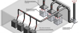
From this article you can learn how to make a wood milling machine with your own hands at home to perform basic operations with workpieces. The text outlines a step-by-step technology for creating a tool: an analysis of the design features of the device and all the components necessary for its installation, drawings with dimensions and detailed descriptions that will help create each of these elements and put them together.
Milling machines are often made to perform multiple functions in woodworking
Selecting materials to create a device
Very often among home craftsmen there are those who try to make their own lathe from an electric drill.
The manufacturing process is not at all complicated, and to achieve the desired result you will need to take all the necessary materials to prepare them in advance. In the production of the machine, woodworking materials can be used, but you should be aware that with such devices you can only process small parts and workpieces, for example, make handles for knives, handles for furniture, etc. If you need a reliable sled that you plan to use very often, then it’s worth investing once and making it out of metal.
Lathe capabilities
Initially, I used a Soviet-made drill with thyristor speed control and a power of only 300 watts. It worked for me until the collector mechanism wore out for more than 30 years under various loads, including extreme drilling of concrete slabs. Rotary hammers were simply not on sale at that time.
This power is enough for leisurely small crafts. But for normal operation, it is better to use the design of a modern drill with at least 800 watts. The difference will immediately be felt.
For many types of work, high rotation speeds are not needed: you have to use a regulator. In this mode, the load on the engine increases, and a reserve of its power, and the entire structure, is simply necessary.
In order to increase the efficiency of the lathe, instead of a drill, I installed a three-phase asynchronous electric motor, giving it a capacitor start from a single-phase network.
This made it possible to turn long and strong workpieces like the handles of shovels and other country tools.
To attach the wooden workpiece to the engine, it was necessary to make a bushing with a locking screw on the rotation shaft and an W-shaped tip inserted into the center of the wood cut.
All the photographs show that my lathe was made a long time ago, and is stored in a workshop where humid air penetrates. Over the course of several years, clearly visible signs of corrosion appeared. Don't let this happen to your instrument.
If you are thinking about creating a lathe design for wood processing not from a drill, but from an asynchronous motor, then it is better to use a three-phase voltage of a standard value of 380 volts to power it. Power losses will be minimal.
For a single-phase 220 V network, you can connect a frequency converter, which will allow you to use all the power inherent in the design of a three-phase asynchronous motor. Such devices are available for sale at a very reasonable price. They are convenient to use on different engines.
When equipping a turner’s workplace, pay special attention to safety measures and the selection of electrical protection. Be sure to connect the electric motor only through a circuit breaker, which eliminates accidents associated with short circuits and overloads
The need to connect a power tool through an RCD is determined by local conditions. But in critical situations, protection is never superfluous.
The design of the tailstock can be improved by including a thrust bearing in the center, for example, size No. 607. The friction spent on rotating the workpiece will immediately decrease, and its combustion will be eliminated.
For a better understanding of the material, we recommend watching the video of the owner Dobry Gena “Do-it-yourself universal lathe from a wood drill.”
Useful products
- Magnetic bracelet - holder
- Souvenir coin for decision making
- Barista thermometer
Make or buy?
An electric drill is a ready-made drive, gear, spindle and chuck in a monoblock. Place it on the carriage of the machine and you can drill. In terms of accuracy, the solution, generally speaking, is not optimal (see below), but in many cases it is acceptable, but eliminates the need to order expensive turned parts of increased accuracy, see below. In view of this, frames for installing drills are now sold only on the street from trays; prices are affordable. When choosing one to make a drilling machine from a drill, be guided primarily by the operating mode of the equipment; The price also depends on it:
- Occasional drilling/milling for yourself with the accuracy of what you get - cast plastic bed or stamped steel. The feed mechanism is lever with a cranked lever (see below). Carriage sliding bearings (see below) are steel on steel or with nylon liners. Prices are $20-$30.
- Regular drilling for yourself or to order with ordinary machine-building precision. The materials processed are up to the hardness and toughness of ordinary structural steel. Everything is the same, but the sliding bearings are steel on steel (worse) or with bronze bushings, and the frame is cast iron or (more expensive) composite, also vibration-absorbing. Prices: $30-$40.
- Regular drilling and milling of any materials that can be tooled with periodic overloads of the tool and/or with increased accuracy - plain bearings are only bronze on steel, cast iron frame. The feed mechanism is rack and pinion (see below); vibration-absorbing console. Prices: $60-$180.
Choosing a bed
The stand for the drill (which sellers for some reason stubbornly call stands) must be chosen not according to - not “China”); Now the market is full of “German China”, not to mention products from post-Soviet states. The design needs to be checked.
First, samples with plastic non-nylon liners for sliding bearings are definitely rejected: runout and drill drift of more than 0.5 mm will appear already on the 10th – 20th “hole” and will further increase. The second is console play. We take it by the far end, swing it up and down and to the sides while holding the latch. There should be no noticeable “chatter” (the tactile sense of an untrained person feels a beat of 0.4-0.5 mm).
Next is an inspection of the structure, see Fig. below. For regular drilling, the one shown in pos. 1. The ideal option is at pos. 2: collet clamp of the drill, shifting the column to the side reduces the vibration of the console by an order of magnitude, and by turning it sideways by 45 degrees, you can mill the part by hand with the precision “as best you can” on a standard fixed table, removing a couple of table fasteners, because in this case, its manual displacement relative to the horizontal working axis of the console will be linear.
How to choose a bed (stand) for a drill
And here is a sample for pos. 3 do not take under any circumstances. Firstly, the collar of its column is low and its fastening is unreliable. Secondly, longitudinal grooves under the table facilitate manual milling “as it happens,” but, unlike diagonal ones, they do not dampen vibrations of the bed. Moreover, they will concentrate where shown by the arrows (the tide under the column is made too narrow) and from there they will go straight into the column and table.
Popular articles Apologies on Forgiveness Sunday
Which is cheaper?
Bench Drill Press Spindle Drawings
Let’s say the price for the machine you like doesn’t suit you. Or a drill, if it’s a “crowbar” one, with an impact mechanism, that was used in work on building structures and the beating of the chuck is visible to the eye. Then the first thing we do is find out if there is a craftsman within reach who owns a lathe with high precision (no rougher than 0.02 mm). Which, by the way, is not a fact - a high-precision machine is very expensive and never pays off with the flow of regular orders. But let's say he was found. We take the drawing in Fig. on the right, we go to him and ask if he can turn it out of steel no worse than 30KhGSA, and how much he will charge for the work. “This” is the drawings of the tabletop drill spindle. The rest of its parts can be turned on a regular machine, or found in ruins at an iron market or in your trash. Most likely, it will turn out that it is cheaper to buy a bed + table, and if you estimate the costs for the rest, then perhaps a drill of increased accuracy will emerge. There are some of these on sale; they can be recognized by the absence of a striking mechanism and a collar specifically for installation in the frame: a turned steel cuff is put on it.
Which is the best wood router?
Now we know enough to choose a horizontal or vertical axis of rotation of the machine spindle. Comparative performance characteristics of horizontal and vertical wood milling machines are summarized in the table:
Horizontal or vertical?
From the data in table. It follows that it makes sense to make a horizontal wood router yourself if you are faced with the need for mass, simple processing of lumber from low-quality raw materials. Not necessarily for sale; perhaps for covering your home with wood siding or clapboard. The savings will be such that it’s time to buy a branded router, but a normal developer doesn’t have extra money. Or, let’s say, still for sale, if you are an individual entrepreneur with a sawmill and a circular saw. Compare market prices for unedged and tongue-and-groove boards, calculate the profitability - is it worth the gamble?
The parts for the most complex module of a horizontal wood router - the spindle assembly - will be made by any skilled turner in a similar way to the same assembly of a circular saw; Structurally, they are the same (see drawings in Fig; sleeve bearings are highlighted in red).
Drawings of a circular saw spindle assembly suitable for a horizontal wood router
The cabinet, dust collector and base plate are the same as for the vertical machine (see below). The plate is even simpler - there is no need for a cutout to mount a vibration-damping motor. The intrinsic vibrations of a horizontal router are an order of magnitude less than those of a vertical router. Transmission from the motor to the spindle further reduces them, and pulleys or sprockets for it can be found in your own trash or at the iron market. An existing circular saw can also be converted into a quite decent horizontal milling machine for wood, see for example. video:
Video: milling machine from a circular saw / jointer
Features of the use of machines
Working with a drill while holding the tool only with your hands significantly limits its capabilities. The weight of the tool and vibration do not allow the drill to be firmly fixed in the desired position. But if you think through and design a special frame where it will be firmly attached, then an ordinary hand drill will turn into professional, almost industrial equipment.
From a drill you can make the following types of machines yourself:
- drilling;
- turning;
- milling;
- grinding.
Moreover, after replacing the working or cutting element, the machines become interchangeable. They provide a two-in-one function, for example, a drilling and milling machine, a lathe and a grinder. It all depends on the installation conditions and the needs of the owner.
The power of the machines and their capabilities will depend on the type of drill (the power of its electric motor), the method of fastening, since in this case it is the main working part of the equipment.
Professional equipment for milling: option No. 3
If you need to perform complex milling operations with maximum accuracy, you need to purchase a factory bed. You can install any router on it and adapt the electric motor for connection. This method is the most expensive, but also reliable.
- presence of coarse and fine feed mechanisms; table with T-shaped slots for fixing the workpiece; the ability to rotate the working head 90° with subsequent fixation; minimum machine assembly time.
The average cost of a bed is 12,000 rubles. These costs are offset by high accuracy and the ability to adapt existing milling equipment to produce a homemade model.
When choosing a factory bed, it is necessary to take into account the dimensions of the work table and the maximum distance from the Morse cone to its surface. The presence of dimensional scales will allow you to perform operations with maximum accuracy.
Also see new technologies in the world of CNC milling and engraving.
How to make a lathe with your own hands
Making a small lathe with your own hands will be greatly simplified if your workshop has a workbench with a flat and durable working surface. In this case, you won’t have to waste time and effort searching. An electric drill, which will simultaneously serve as a headstock and a rotation drive, is secured to such a surface using a clamp and a clamp fixed to the neck of the tool.
Version of the machine with a wooden bed
Now you need to make a stop that will act as a tailstock. Such a stop, installed opposite the fixed tool, can be made from a pair of wooden blocks and an adjusting screw, the end of which is sharpened to a cone. If you plan to process not very massive wood workpieces using your homemade drill machine, then you can fix such an emphasis on the surface of the work table using a clamp.
You can also use a wooden block as a support, against the supporting surface of which you will press the cutting tool. It is secured to the surface of the workbench using a clamp.
Obviously, using available and inexpensive materials, you can make a simple lathe with your own hands, on which various woodworking operations can be successfully performed. Using such a simple device, made on the basis of a drill, you can turn various parts from wood: handles for doors and tools, structural elements of stairs, decorative items.
Scheme and drawing of a machine on a channel base
The design of such drill-based machines and their design options can be different.
In order not to understand the process from scratch, you can find on the Internet a photo of the device that best suits you and make it yourself. However, no matter what scheme you use to make a turning device from a drill, it is very important to ensure the most accurate alignment of the axis of rotation of the spindle assembly and the conical adjusting screw located on the tailstock
If you are going to make a machine on which you can perform turning operations on metal, and not just on wood, then it is better to make it according to all the rules. First of all, focusing on the design of the existing drill and the dimensions of the workpieces that will be processed on such a device, it is necessary to make a drawing and select a specific shape and type of fastener for the assembly. As a basis for the drawing, you can take a photo of similar units that many home craftsmen make for themselves.
A homemade lathe, made according to all the rules, is a rigid structure on which the mutual alignment of the front and tailstocks does not change. All moving elements of such a device, installed on a reliable frame, move along its guides. If you purchase or make your own faceplate, which will be fixed in the drill chuck, such a unit will be able to process workpieces of even large diameter.
With a drill, all of whose elements are fixed on a rigid frame, you can perform work on metal, but only on soft metal (this includes alloys based on aluminum and copper). On such a machine, workpieces are processed using a needle file, a file and sandpaper wrapped around a block. In this case, the tool rest used to hold the tool will be quite sufficient. If you plan to work with turning tools, then you cannot do without a support, the movement of which in the longitudinal and transverse directions is ensured by a screw mechanism.
A factory turning device for a drill, like the one shown in the photo GRIZZLY H2669, will cost about 5,000 rubles without delivery
Materials and tools
List of tools and materials required for assembly:
- Chipboard or a sheet of plywood approximately 12 mm thick is suitable for making a tabletop (the exact dimensions are selected individually).
- Boards of suitable thickness.
- Several wooden blocks.
- Self-tapping screws, screwdriver or screwdriver.
- Ruler and pencil for marking.
Important! If the design should ultimately be as reliable as possible, you can use metal (pipes, corners) instead of wood.
It is advisable to coat the wood with construction glue or PVA. To secure the moving units, studs or bolts with a diameter of 8 mm are used. You need to select nuts for them (regular and wing nuts).
Device
The traditional version of a lathe includes the following main components: electric drive, bed (base), headstock, tailstock, caliper. An electric drill is used as an energy source (electric drive) on a homemade lathe.
bed
Designed to accommodate all other nodes. She takes all the workload on herself. Therefore, the bed must have a margin of safety. The design is minimally deformed during work, ensuring precision in the manufacture of parts.
The bed is highlighted in red
In the classic version of a lathe, the bed is a technologically difficult unit to manufacture. Its surface, mating with other assembly units included in the lathe, is made with high precision requirements. In the process of its technological processing, special high-precision equipment is used.
Headstock
In the headstock of the lathe there is an electric motor with a gearbox and a control unit. Its functions include transmission of rotation, as well as positioning of the workpiece for processing. Another name for the headstock is spindle, because the main part of this unit is the spindle. This is a multi-stage shaft with a hole inside, rotating in precision adjustable bearings.
On the side of the working area there is a flange to which a three-jaw self-centering chuck is attached. Various clamping devices, such as a collet, are installed through the holes in the shaft. Fastening the workpiece in a homemade machine is carried out using a drill chuck of an electric drill, that is, it has significant limitations.
Popular articles Apologies on Forgiveness SundayThe control unit of a conventional lathe allows you to select almost any option for processing the part according to the technological process. In the homemade version, the function of the headstock is performed by an electric drill along with the base on which it is attached. Therefore, the choice of workpiece processing mode is limited by the functionality of the power tool.
Tailstock
To create the necessary rigidity during processing, the workpiece is fixed on both sides
This is especially important for long parts. Therefore, the back one is located opposite the front headstock.
In the tailstock body there is a thrust or rotating center that serves to press the workpiece. Cutting tools such as drills, countersinks, and reamers can be installed in the tailstock.
Caliper
The lathe support ensures that the tool is fed into the processing area. Typically, the tool is mounted in a special tool (tool holder), which is placed on the support. The kinematic design of the support allows it to move both longitudinally and transversely relative to the spindle axis. To obtain conical surfaces, the tool can be installed at an angle.
The working tools of lathes are driven both manually and with the help of mechanical devices. On homemade lathes, the tool is fed into the cutting zone mainly using manual physical force.
Design features and device of the milling cutter
A milling cutter is a unit for processing wood or metal, designed primarily for cutting technological recesses. The device consists of a housing in which key components are located, a motor and a holder for installing collet adapters for cutters. At the bottom of the unit there is a platform made of cast or stamped metal.
When turned on, the electric motor of the milling cutter imparts rotation to the shaft and sets the milling attachment in motion. The tool allows you to make grooves and cavities in wood, process the edges of parts or create threads without wasting time and extra effort.
Design of a homemade lathe from a drill
Drawings of a lathe from a drill consist of four important components: bed, headstock, tailstock, support (support).
A homemade lathe made from a drill must have a reliable, stable base, which ensures quality, accuracy and ease of processing various materials.
The most precise industrial units for metal, wood, and other materials are equipped with a massive frame on legs.
It is better for a home craftsman to make his machine more mobile. Accordingly, the frame should be light or collapsible.
With its help, the machine can be installed on a table, workbench, cabinet, moving it as needed.
The main thing is that the bed fulfills its main function, being a rigid, reliable base on which the main functional components of the machine are correctly located.
Headstock - the main task of this unit is to rigidly fix and ensure rotation of the workpiece being processed.
During operation, the part must be firmly fixed in one place and not move under the influence of vibrations.
On the other hand, the headstock can move longitudinally.
Thanks to this, it is possible to optimally arrange the working units of the device depending on the size of the workpiece being processed.
On stationary industrial machines, such a functional unit is included in the monolithic structure of the entire frame.
A homemade lathe, made from a do-it-yourself drill, uses a hammer drill or drill as this important functional part of the device, which can be easily removed if necessary. The tailstock is a movable unit of the machine that can be easily fixed in the desired place on the bed
Due to mobility, you can install workpieces of different lengths
The tailstock is a movable unit of the machine that can be easily fixed in the desired place on the bed. Due to its mobility, workpieces of different lengths can be installed.
A correctly made such device should have the most accurate adjustment of the thrust cone.
The correct pattern of the relative position of the two “headstocks” allows you to securely secure the workpieces during processing.
Caliper (hand rest) - the main task of this element of a lathe from a household drill is to act as a stop for cutting tools, which are mainly held by hand.
This device can move along the frame in the longitudinal and transverse directions and be rigidly fixed during operation.
It is important to install the support in such a position that the cutting tool arm to the workpiece is as short as possible. Video:
Video:
This will ensure safety when working with various workpieces.
It is important to consider that in a homemade lathe, the caliper has the greatest freedom of movement, moving in the longitudinal and transverse directions. This ensures an optimal working position with the desired tool lever arm.
This ensures an optimal working position with the desired tool lever arm.
The remaining two mobile units of the unit must move only along guides along the axis of the workpiece.
Making it vertical
A vertical wood milling machine has much greater functionality and provides better quality of material processing than a horizontal one. It is vertical milling machines that are mostly built by home-made amateurs. However, the problem of combating vibrations in a vertical milling machine is much more acute. If in a horizontal router vibrations through the base of the spindle unit are given priority. down and are effectively damped, being reflected in the thickness of the material, then in a vertical machine, elastic waves in the machine plate propagate mainly to the sides. In this case, their inerference is possible and the emergence of standing waves with antinodes (foci) of such a size that the workpiece is thrown away from the cutter. Therefore, one of the main tasks of designing a homemade vertical router is to suppress machine vibrations.
Structural diagram
Vertical milling machines with a bottom drive of a free (fixed only from below) cutter are least susceptible to vibration. The working body is mounted directly on the motor shaft. The entire drive is made as vibration-resistant as possible. Under the influence of the beating of the cutter on irregularities in the workpiece, the drive staggers and sways. At the same time, a noticeable transverse (vertical) component appears in the waves of elasticity, effectively absorbed by the frame, and a heavy motor with a massive, rapidly rotating rotor plays the role of an inertial absorber of mechanical vibrations.
The structure of industrial and homemade vertical wood milling machines is shown in the figure:
Construction of industrial and homemade vertical milling machines for wood with bottom drive
Their main difference is in the folding (lifting) stop 7. Since amateur designs do not use drives of 5 kW or more with high-performance cutters, the folding stop is replaced by a lifting one, which prevents the workpiece from being squeezed upward from the cutter. Also, for an amateur machine, an adapter attachment with a Morse taper on the motor shaft is machined to order, the same as for a homemade drilling machine. A standard clamping chuck for a cylindrical shank is installed on the cone. In this design, it is also possible to use mounted cutters: adapters for them with a cylindrical shank are commercially available or are included in the set of cutters. The most important structural components of such a machine are:
- The base plate is the main damper of longitudinal (horizontal) elastic waves in the machine;
- Vibration damping drive board;
- Comb stops (stop) – dampen vertical vibrations of the workpiece;
- Static side stop - ensures correct feeding of the workpiece, and in a homemade machine also some adjustment of the cutter output (horizontal processing depth);
- Dust collector – removes processing waste to the dust collector.
The latter is absolutely necessary when milling, because The cutter produces several times more wood dust, sawdust and shavings than is produced during sawing. The base plate is most often made integral with the vibration damping suspension of the drive. The cabinet (bed) can be anything, as long as the slab and other parts do not fall down.
Drive plate and suspension
Installing the drive of a homemade wood milling machine into the base plate
The window (opening) for hanging the drive from the machine plate is most often cut out square (see figure on the right), this is easier at home. But the machine will tremble much less during operation if the window for the drive is made round. In any case, the motor should not directly touch the plate (again, see the figure on the right), otherwise, instead of dampening vibrations, they will be amplified.
The best materials for the plate and drive board are fiber-laminated plastics: textolite, fiberglass with a thickness of 12-15 mm; the thicker the better. Hardboard and other massive plastics are less suitable: they dampen vibrations well, but over time they warp when heated by the motor and the machine loses accuracy. Getinax and other thermosetting laminates are unsuitable: they delaminate very quickly due to vibrations.
However, it is neither possible nor practical to make the entire slab as one piece: it is difficult, expensive, and the vibrations of the drive itself will be freely transmitted to the slab. You only need to make the motor board from plastic, and the slab from plywood impregnated with a vibration-absorbing composition and glued together, and low-grade construction and packaging material will do. The slab must be re-glued with at least 5 sheets so that the fibers of the outer layers of adjacent layers are oriented mutually perpendicular.
The cutting diagram for a standard sheet of plywood 1550x1550x4 mm into sheets for the base plate of a wood milling machine is given on the left in Fig. Sheets for the horizontal router plate are cut out without windows for the motor, but with a dust collector socket (see above and below). Slab size up to 750x500 mm. A 50 mm flash along the contour of the sheet is needed to cut off low-quality material at the edges.
Scheme for cutting a sheet of plywood and a device for suspending the drive of a homemade wood milling machine
The sheet is first generously impregnated 2-3 times on each side with eco-construction soil (water-polymer emulsion), it perfectly dampens vibrations. The interval between impregnations is at least 3.5 hours. Then the sheet is cut out and a plastic film is spread on the floor (not PVC, it will stick!). Sheet No. 1 is placed on the film and with a brush (preferably a “shaggy” paint roller) a thin, even layer of mounting (reinforced) PVA is applied to it; the same layer is placed on the adjacent side of sheet No. 2. Immediately after applying the glue, the brush (roller and its tray) are thrown into a bucket of water, and after all gluing is completed, they are washed in water.
Before folding, the sheets are kept for 15-20 minutes (or according to the instructions on the glue package), folded and straightened, without being separated, so that the edges of the drive window meet exactly. Then sheets No. 3, 4 and 5 are glued in the same way. The entire package is covered with film and loaded over the entire area with a dispersed load of 30-40 kg (it is best to pile on more books or magazine files). Dry for at least 3 days at room temperature: mounting PVA is durable, its adhesive layer is viscous and perfectly absorbs vibrations, but takes a long time to dry to full strength.
The design of the motor suspension is shown in the section on the right in Fig. A gap of 0.5-1 mm should be left between the motor board and the machine plate. There is no need to clean sawdust out of it: it will serve as an additional side vibration-damping cushion. It is advisable to find a motor with mounting feet that protrude beyond the dimensions of the housing: then it will be possible to install (not quickly) the extension of the cutter upwards. To set the cutter in height, the motor mounting screws are taken long, and the stem itself is set by putting steel washers on them, between the rubber suspension cushion and the motor body, alternately with gaskets made from the same tube-type truck tire.
The slab with the hanger is checked for workmanship with a pencil. If you place it sticking out 5 cm from the edge of the suspension board, then when the engine is on at idle, the pencil should not fall.
Stop and dust collector
For a drawing of a simple but good static side stop with a dust collector socket, see the following. rice. The material is re-glued plywood from the same sheet. Holes for the comb and lifting stops are drilled in 3-5 pieces: the first 50 mm from the edges of the cutout for the cutter (rectangular); the rest after 25-30 mm. The position of the stops is selected depending on the size of the workpiece and the quality of its material. The lateral offset of the cutter is adjusted within small limits by turning the stop and securing it with a clamp.
Drawing of a side support with a dust collector for a homemade wood milling machine
Dust collector
Dust collector device for a homemade wood milling machine
Since there is no industrial pneumatic system with air extraction at home, milling dust has to be sucked out with a household vacuum cleaner. If you connect it directly to the dust collector pipe, the required expensive household appliance will soon fail. An expensive, well-cleaning vacuum cleaner with a hydraulic separator will most likely immediately. So, in addition to a dust collector, a homemade wood router also requires a dust collector, through which the vacuum cleaner is connected.
The design of a dust collector for a milling machine is shown in Fig. on right. The container is round, from 10-15 l (preferably from 20 l). The ideal option is a household bucket with a tight lid, fitted with a seal and equipped with snap-on latches (both can be done with your own hands).
Inlet pipe – diameter approx. 20 mm (inside). Its end is beveled 45 degrees and rotated 20-30 degrees outward; installed 15-20 mm from the side of the vessel (counting from the outer edge of the pipe). The exhaust pipe is wider, approx. 30 mm inside; is installed exactly along the vertical axis of the container. Its selected end is narrowed to 15-20 mm (the taper is not critical). Everything works together like a cyclone, and the air entering the vacuum cleaner is clean enough not to spoil the device.
Note: an additional advantage of the dust collector is that the dust from it is an excellent filler for high-quality wood putty. For this, the dust is mixed with PVA (3-4):1 by volume.
Comb
A drawing of the comb stop of a wood milling machine is given in the following. rice. Material – hard elastic fine-grained wood (oak, beech, walnut) without defects – strands, rot, cross-layers, knots – 20 mm thick. A pair of combs is needed, right and left, so that the workpiece can be fed from either side.
Drawing of a comb stop for a homemade wood milling machine
The first comb tooth along the workpiece (pay attention!) is shortened by 3 mm. It does not directly contact the workpiece, but serves as a rebound spring for the entire comb. Without it, the comb may get caught in the workpiece and break.
Fastening the combs to the side stop - with a bolt with a wing nut through a longitudinal groove (slotted hole in the figure); fixing the non-working one with a self-tapping screw to the same stop through hole D7. The comb is placed in the working position so that it touches the workpiece with all teeth except the first, and is fixed with a thumb.
Common Mistakes
If mistakes are made during the manufacturing process of a home drilling machine, all the costs of money, time and other resources will be wasted. Typical errors are shown in the figure:
Each figure shows the following typical errors:
errors in the manufacturing process of a home drilling machine
- Low accuracy and weakness of the frame under the influence of standard load;
- The column should not be hollow inside, otherwise it will not withstand the bending load;
- The rod will not support the tool stop.
- There is no point in doubling the column transversely. This will not increase stability.
- The bump stop (in this case, the spring), due to its disproportionate size, does not dampen loads and vibrations, but rather enhances them.
- An asymmetrical arrangement of the drive and spindle on one side of the column will only increase vibrations.
- The main mistake is the lack of a bump stop as such. It must not be used as it is hazardous to health.
Many owners who independently engage in construction and construction have an electric drill. However, one such tool may not be enough for operations requiring high precision, right angle drilling or complex tasks. To achieve these goals, drilling machines are created - installations that can be made at home from scrap materials and household appliances. There is nothing complicated about how to make a drilling machine from a drill.
Additional materials (drawings):
how to make a drilling machine from a drill with your own hands drawings
how to make a drilling machine from a drill with your own hands drawings
how to make a drilling machine from a drill with your own hands drawings
Summary
Article Name Do-it-yourself drilling machine from a drill - detailed instructions, drawings
Description It is better to make or buy ➜— Do-it-yourself drilling machine ➜— Common mistakes ➜— Drawings ➜— Location of the main structural elements.
Author
Publisher Name
Wikipedia of construction tools
Publisher Logo
Preparing for work
Before constructing a homemade combined machine with your own hands, you need to prepare the following materials and tools:
Tools
- drilling machine;
- band saw or jigsaw;
- screwdriver;
- clamps;
- ruler, pencil;
- hand cutter;
- cutter-crown 30 mm.
Materials
| Name | View | Quantity |
| Sanded plywood | 15 mm | 1 |
| Wooden block | 8x9x650 mm | 1 |
| Wooden block | 290x27x16 mm | 1 |
| Wood glue | ||
| Sandpaper |
Accessories
| Name | View | Quantity |
| bolt with nut and washer | 6x55 mm | 3 |
| furniture steel coupling with slot | DIN 7965, internal diameter M6 | 2 |
| metal strip | 0.5x10x200 | 1 |
| hook screw | 3x30 mm | 1 |
| aluminum sleeve in the form of a tube | Outer diameter 10mm, length 23mm, 2mm wall thickness | 1 |
| steel clamp | According to the diameter of the router | 1 |
| self-tapping screws | 35 mm | 20 |
| mini router | 1 |
Design elements
Figure 2.
Figure 3.
Figure 4.
- Drill version cover.
Figure 5.
Figure 6.
Figure 7.
Woodworking Machine
The woodworking equipment market offers an extensive line of wood lathes. Each consumer makes his choice taking into account his interests, but the main criterion is the drive power. For a home workshop where turning work is performed sporadically, a simple tabletop machine with an electric motor power of 1 kilowatt and a spindle speed of 3500 rpm is suitable.
https://youtube.com/watch?v=xs8KOp1HoFI
The main components and mechanisms of a wood lathe correspond to the classic structure of a lathe, which processes workpieces by rotation. Three main mechanisms:
- drive - electric motor, single-phase or three-phase;
- transmission - a set of devices that transmit the rotation of the motor shaft to the spindle head;
- the executive is the support.
Four main nodes:
- bed - the body on which the mechanisms are fixed;
- front spindle headstock - for attaching a faceplate or lathe chuck;
- rear fixing headstock - for installing a rotating center or drill chuck.
Popular articles Dragon made of polyurethane foam
Design feature
You can assemble a wood lathe with your own hands from available materials. The design is simple and does not require much time to manufacture. The main part of the machine is a bed made of a channel, in which a groove is cut along the central center line with a grinder for fixing the tool rest and tailstock. The fixation principle is an eccentric mechanism.
The tailstock design is standard. The quill has a hole for Morse taper No. 2 to set the center of rotation. The drill chuck shank matches the quill hole. It is recommended to use a factory made tailstock.
Under the quill, machine a hollow cylinder with a blank end wall, in which a thread is cut for the flywheel screw. The moving part of the quill is a cylinder with a conical hole and a keyway along its entire length. The moving part moves with the help of a flywheel screw along a key welded in the headstock body.
The tool rest is classic, has an adjustment function with fixation to the diameter of the workpiece being processed, the base of the tool rest moves across and along the bed. It is fixed with an eccentric with a handle. The upper part is a regular corner.
The headstock has two angular contact bearings. The spindle shaft has an M14 thread, step two. This is a thread that is used on grinders and grinders. Thanks to this, all the attachments used by the grinder can be attached to the spindle.
DIY spindle head
The quality of the entire structure depends on the accuracy of the headstock manufacturing
Therefore, special attention must be paid to this node. Craftsmen recommend making the headstock of a lathe with your own hands
To do this, you need to machine a cylindrical body with a wall thickness of 10 mm. To attach it to the frame, you need to make a special stand. A section of channel is suitable for this. The channel end is welded to a corner made of sheet steel 10 mm thick. The headstock body is attached to the resulting stand.
To make a wood lathe with your own hands, drawings and dimensions do not matter, since everyone makes the design individually, taking into account their capabilities. Sectional view of a cylindrical body:
- outer diameter 56 millimeters;
- wall thickness 10 millimeters;
- length 180 millimeters;
- mounting sockets for bearings with a diameter of 24 millimeters;
- shaft with a diameter of 30 millimeters.
Simple accessories make the machine universal and increase the list of operations. For example, by installing a sanding drum with sandpaper in the chuck, you can sharpen the tool. The device for turning on a copy machine looks like this:
- copier;
- a pipe installed along the frame, acting as a slide;
- circular electric saw that acts as a wood cutter.
The milling attachment will replace the milling machine. Arbor with disc cutter
is clamped into the chuck. Instead of a tool rest, a work table with a stop ruler is installed. You can mill platbands, baseboards, and blanks for frames.
Enthusiasts and lovers of making homemade items are constantly coming up with mechanisms that make manual labor easier. Such people always have an answer to the question of how to make a woodworking machine.
Which one should I do?
Dozens of different milling operations and at least a dozen types of machines for them are used to process materials. At home, not all of their designs can be repeated by beginners and intermediate craftsmen. 2- and 3-axis CNC machines (2D and 3D wood milling machines) are not discussed in this article. It is possible to make a 2D or 3D milling machine yourself (item 1 in the figure below), but already having quite a lot of experience working on a simple machine, a significant volume of orders and an urgent need for a sharp increase in labor productivity. At the same time, you will have to master programming microcontrollers, because... finished samples are designed for a machine of a very specific design; There will also be significant costs for stepper motors and precision drive parts.
Types of homemade wood milling machines
To begin with, at home, you can make a homemade milling machine using any of the following. varieties:
- Horizontal (item 2 in the figure).
- Vertical (item 3).
- Flat copy machine with pantograph (2D duplicator, item 4).
- Machine for volumetric copying (3D duplicator, item 5).
Tool…
The choice of a machine of one type or another is determined, of course, by the work operations most used by the master. To specify their nomenclature, you must first decide which working parts (cutters) you will most need. Most of them are applicable in both horizontal and vertical machines.
Types of wood cutters
Mounted cutters (item 1 in the figure) are processed primarily. straight edges of the boards: grooves and ridges (including shaped ones) are cut out to their full length, and a chamfer is applied. The spindle assembly of the machine for attachment cutters (see below) is structurally the simplest; its parts can be turned by a 3rd class turner. The required drive power for a processing depth of up to 60 mm is from 1.5 kW. The quality of the material is almost any, ranging from raw material straight from the sawmill. A vertical wood router is most suitable for attachment cutters, see for example. Below is a video in 4 parts:
Video: homemade wood milling machine with attachment cutters
There are many more varieties of milling cutters with a cylindrical shank (landing, seating), because their functionality is wider. But for such a cutter it will be necessary to machine a spindle attachment with a Morse taper for a clamping chuck; It is also possible to use ready-made spindle units from a drilling machine.
End mills, e.g. Forstner cutter (item 2 in the figure above) is a specialized tool; They choose round holes with a flat bottom in thin boards with a decorative coating that cannot be damaged. Have you ever hung doors on furniture? The holes for their loops were chosen using a Forstner cutter. The quality of the material is no worse than straight-layered wood of the 1st grade, chamber dried. Required drive power from 150 W. They work with end mills only on a vertical machine or, with a certain skill, manually.
Note: using a Forstner cutter in a 170 W screwdriver to select holes D32 for door hinges in furniture chipboard 16 mm thick is quite possible, I did it myself.
End (finger) milling cutter, pos. 3, can be threaded into both horizontal and vertical spindles. Using end mills, blind grooves are selected (not the entire length of the board) and tenons are cut for tongue-and-groove joinery joints. It is more convenient to work with an end mill on a horizontal machine. On a vertical surface, it can be used to select long grooves (grooves) of a rectangular profile on the surfaces of boards and beams. Tapered end mills (item 4) are also a specialized tool for preparing parts for dovetail joints. They work with conical end mills only on a vertical machine. For both of them, the required drive power for a processing depth of up to 80-100 mm is from 1 kW. The quality of the material is from commercial wood of the 2nd grade, air dried (from a timber exchange).
End shaped (curly) cutters, pos. 5, also a specialized, but highly sought after tool. They apply molding (including on curved edges) and select shaped grooves (decorative grooves) of any configuration in the faces of the boards. Drive power from 1.2-1.5 kW; The quality requirements for the material are the same as for end mills. To process edges, the shaped cutter can be threaded into either a horizontal or vertical spindle; for working on layers only in a vertical position.
Roller-cone cutters (burrs, item 6) can also be used to select shaped grooves and create a groove on both a horizontal and vertical machine, but in general they are a special tool for copy milling machines. The requirements for the quality of the material are high, as for end mills, but the drive power in the copier can be from 250-300 W.
And, finally, using a circular cutter (item 7) in a vertical milling or drilling machine, round holes of large diameter are cut out in almost any material that is not overly thick (including sheet metal). Required drive power per hole D200 in 60 mm thick oak board approx. 2-2.5 kW.
...and his presentation
Milling can be done in two ways: up and down, see fig. below. As for wood, ordinary straight-layered wood (especially one that is not of very high quality air-dried) is milled only along the way, otherwise the milling cutter can even split and/or fray the workpiece. But in this case, with an excessive feed rate, there is a considerable probability of the workpiece being pulled away by the cutter and damage to the processing profile. Removing dust, sawdust and shavings from the working area (and this is a serious problem) on a vertical milling machine during down milling is difficult, because The dust collector (see below) has to be placed in the field of view in front of the cutter and it obscures the working area.
Up and down milling methods
Note: on a horizontal milling machine there are no problems with removing processing waste during down milling, because dust (sawdust) then flies down, and the dust collector socket can be placed directly on the machine plate (see item 2 in the figure at the beginning and below).
Up milling gives better precision and cleanliness of processing, but only on sufficiently high-quality and homogeneous materials. From wood - on solid, fine-grained wood, chamber dried. Removing processing waste on a vertical milling machine is easier, but on a horizontal one it is difficult - dust and sawdust fly upward. The removal of the workpiece is almost impossible, but there is a danger of it being bitten by the cutter. A well-behaved profile can often be modified; a bitten and broken piece is an unconditional defect.
Motor
Based on the above, it is optimal to make a do-it-yourself milling machine with a drive with a power of 1.5-2 kW. The reason is that motors up to this power are produced, incl. asynchronous with capacitor starting for voltage 220 V 50 Hz. They can be plugged into a regular household outlet, and switching the direction of rotation is a child's task for an amateur electrician; rotation speed is 700-2850 rpm, which is suitable for milling. It is also possible to use an electric motor of the same type from a washing machine; in this case, it becomes possible to switch the rotation speed (in asynchronous washing machine motors there are different windings for this). A 2 kW motor will provide a processing depth of up to 80-100 mm; if a larger one is required, you will have to install a three-phase motor at 380 V 50 Hz from 3 kW into the machine, see for example. video clip:
Video: homemade vertical milling machine for wood
Note: commutator electric motors of 1.5-2 kW 220 V 50/60 Hz (for example, from another washing machine or vacuum cleaner) are of little use for driving a milling machine - due to their excessively soft external characteristics, the cutter may get stuck in the wood if the workpiece is not manually fed, tear and rag it (if it’s damp).
Lathe device
Regardless of the size or purpose, at their core, lathes are designed the same, they just have features that depend on the area of its application. In order to figure out how to make a lathe with your own hands, we need to take a closer look at this very device.
Many people from the school labor course can remember that the basis of everything is the bed. It is on this part that all the parts for fastening and moving the workpiece are located. It is the basis of the entire structure, and the stability and reliability of the entire machine depends on it.
For household needs, a tabletop machine will be sufficient, which does not require additional stability, making it much easier.
Next comes the headstock. Of the two main parts that are responsible for fixing the workpiece, this one is located on the side of the rotating element.
All drawings of a lathe from a drill have such a detail in their design. It is used to center the part that will be processed, and transmits the driving moment, which, in our case, will come from the drill. If the machine is a heavy model, this part will be welded to the frame, and only the height will be adjusted.
There is also a tailstock, which also acts as a fastening device. It is a moving part whose task is to secure the part and press it against the chuck, which will be mounted on the headstock. In the case of heavy machines, this part moves not only vertically, but also horizontally, thereby making it possible to process larger parts.
Last, but not least, is the caliper. It is necessary for working with the part and processing it
It does not hold it, but at the same time acts as a stop for your instrument. It is possible to work without it, but it will be terribly inconvenient, and the overall quality of the part will suffer, which is not desirable.
Professional equipment for milling: option No. 3
If you need to perform complex milling operations with maximum accuracy, you need to purchase a factory bed. You can install any router on it and adapt the electric motor for connection. This method is the most expensive, but also reliable.
- presence of coarse and fine feed mechanisms; table with T-shaped slots for fixing the workpiece; the ability to rotate the working head 90° with subsequent fixation; minimum machine assembly time.
The average cost of a bed is 12,000 rubles. These costs are offset by high accuracy and the ability to adapt existing milling equipment to produce a homemade model.
When choosing a factory bed, it is necessary to take into account the dimensions of the work table and the maximum distance from the Morse cone to its surface. The presence of dimensional scales will allow you to perform operations with maximum accuracy.
Also see new technologies in the world of CNC milling and engraving.
Types of do-it-yourself drilling machines
There are different types of drill presses made at home. They differ in: material of manufacture, structure, size.
And home craftsmen never stop coming up with new designs and selecting sizes for drilling machines. After all, not everyone makes machines according to ready-made drawings.
Here are some of the most popular drill press designs:
Wireless machine made of wood. This design is well suited for portable drilling of large items. Since the operation of the drill in such a machine is provided by the battery, it is necessary to make a special wooden box. The machine drawing is adjusted independently to the dimensions of the built-in drill.
Mini drilling machine. Making such a tool will not take much effort and time. This design is considered the most economical and does not require a large amount of materials. The model is designed depending on the size and shape of the drill; the drill itself can be secured with ordinary rubber bands or cable ties.
Machine made of plastic pipes. This option is good for those who have pipe scraps left after plumbing repairs. In another case, this option is very economical, since PVC pipes are cheaper than metal or wood. It’s not that difficult to make, the main thing is to maintain the proportions and dimensions.
The feasibility of creating a homemade turning unit
The range of capabilities of the machine - homemade drills is not limited to repair work on small wood products and the creation of wooden crafts.
Additional features:
- Sharpening metal knives, drills, chisels and other household items. To do this, it is necessary, by installing an additional stop, to equip the machine with a round emery stone driven by an electric drill motor.
- Processing of parts made of organic glass, plexiglass, wood. A plywood disc with sanding paper is installed in the electric drill chuck. The role of the stop is performed by a wooden stand for placing the workpiece.
- Sanding any wooden and metal products with a rubber wheel complete with sandpaper.
- Polishing household metal utensils and wooden objects with a felt disc to a perfect shine.
All these additional features are strong arguments in favor of creating your own home lathe equipment.