Scheme of Connecting a Generator to the Home Network
The number of phases that will be used in the generator depends on how many phases come from the main power supply.
Just one turn of the switch or operation in fully automatic mode and you will feel calm and safe. Generator autostart The most complete way to switch the load is using an automatic transfer switch.
Here it also makes sense to use partial automation, since semi-automatic machines are inexpensive. 220V home generator with autostart system from Kirill Plisov. It will be interesting to read:. The nuances are that when connecting a gas generator to the network, it is necessary not only not to confuse the phase-zero polarity, but also in some RCDs the power source is connected to the upper terminals, and the load to the lower ones.
Otherwise, you can get heavy fines for illegal tapping. At the location of the electrical panel.
Do not wear loose clothing, as the fan inside can pull in the fabric and other items of clothing. Connecting a single-phase generator to a three-phase network at home will not be a problem, the main thing is that the generator’s power is enough to consume the most important consumers in the house.
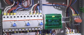
Preference should be given to a brushless design with better current characteristics and less radio interference. ATS circuit with two contactors and a phase control relay
Application of ABP
The autostart system is more expensive than the manual one, but it constantly monitors the network voltage. When the voltage disappears, the contactor interrupts the connection between the ATS and the central power grid. The starter turns on and the generator starts working. Most generator owners prefer using cheaper partial automation, which works as follows:
- The main power supply is connected through a contactor that opens when the input is disconnected.
- The gas generator is started manually. A time relay is installed in it to warm up the engine and automatically switch to connecting the reserve to the home network.
- When the power supply is restored, the contactor is switched off and the load is supplied again from the public network.
A fully automated power supply system regulates the operation of the gas generator using microprocessors. Video on this topic
How to connect a single-phase generator?
There are several connection options. The first is connecting the unit to a designated group of consumers.
Connecting voltage in manual mode
The second method is to use a rocker switch (switch) in 3 positions 1-0-2, in other words, in the 1st position, power is taken from the centralized (city) electrical network, switch position 0 - the electrical circuit is turned off, in position 2 - home connected to a backup source of electricity, in this option it is a gas, gasoline or diesel generator.
Without delving too deeply into the structure of the devices, we only note that the design of a changeover switch or a 3-position switch is quite simple and includes stationary contacts to which the wiring is connected (consumer-city-device generating electricity), and movable contacts that switch the consumer from the centralized power grid to the generator and back.
When switching a 3-phase load, the city-consumer will switch 3 phases, in other words, 3 city phases A-B-C go to the switch, and the same 3 phases go to the consumer.
When switching the consumer to the generator, we need to do it in such a way that all 3 phases receive electricity.
In this case, it is necessary to slightly modify the switch-switch - make a jumper between phases A-B-C on the side connecting the device that generates electricity. Now, when the consumer switches to the generator, electric current will flow to all 3 phases.
Connecting the consumer via contactors
The third way to connect a consumer to a single-phase generator is to use contactors. With this option, 2 contactors are used, one to power the consumer from a centralized network, the 2nd contactor is needed to connect the consumer to a backup source of electricity - a gas, gasoline or diesel generator. This method is acceptable when using automatic backup power (ABP).
When the consumer is powered from a centralized network, all 3 phases connected to the contactor go to the consumer. When connecting a generator, as in the version with a 3-position switch, at the contactor terminals in the area where the cable from the generator is connected, we need to slightly modify the switch switch - place a jumper between phases A-B-C.
When operating a single-phase generator, it is necessary to take into account that if there is 3-phase equipment, it must be disconnected from the power supply while the generator is operating, since this can cause breakdown of these devices.
Connecting three-phase models
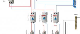
Connection via an additional distribution machine. The circuit diagram for connecting the machines from the power line and the generator is almost the same, which makes it possible not to change anything in a functioning 3-phase electrical network. This approach to introducing an individual home into the network is considered the most reliable and ensures the efficient operation of the equipment connected to it.
To implement it, you will need to take certain actions.
- Turn off the 380 V input circuit breaker, stopping the supply of current to the house.
- Install a new 4-pole circuit breaker in the panel, the output terminals of which are connected by pieces of wire to the input terminals of all linear devices.
- The generator output cable with 4 wires (3 phases and neutral) is fed to the new circuit breaker, and each of them is connected to the correct terminal.
- If a residual current device is installed further in the diagram, when performing switching, the wiring of the wires connected to it (each of 3 phases and zero) is provided.
Connection via switch
A changeover switch (reversing switch) is the same switch, only with three positions.
When using it, the busbars from the generator are connected to one group of poles, and the supply wires from the power line are connected to another.
The central group of contacts of the switch, the wires from which go directly to the consumer, are sequentially transferred towards the input from the explosive or to the generator supply. In the middle position of the switch, the entire house is completely de-energized.
Device and main parameters of generation
Three-phase generator design
A three-phase generator is a device that operates on the principle of converting the mechanical energy of a rotating shaft into electricity. In addition to the moving part associated with the drive, it consists of three coils made up of many windings and placed on the stator core. In brushless generators, when the rotor rotates, an EMF is induced in the coils, whose parameters correspond to the standards of 3-phase mains power. This means the following:
- the resulting voltages have a sinusoidal shape;
- the amplitude of each of the 3 phases is 220 Volts;
- the voltage between them is 380 Volts;
- frequency of generated oscillations – 50 Hz.
A design feature of such units is a phase shift of 120 degrees.
An alternating voltage is supplied from the stator coils to the serviced line, providing it with the necessary power of 380 Volts.
How to connect a single-phase generator to a three-phase network.
How to connect a generator to the house ? It would seem that it could be simpler, start the generator, connect it to the house and that’s it, we live as before))). In previous articles, we have already looked at how to connect a generator to the house and the main mistakes that can lead to big troubles, the smallest of which is the failure of the generator.
In this article I would like to consider the issue of connecting a single-phase generator to the house
, in which all electrical wiring is designed and executed for a three-phase network. Oddly enough, many electricians, even with decent work experience, fall into a stupor and begin to reinvent the wheel))).
The most optimal solution when connecting a generator to the house
,
This is when, even at the stage of construction and electrical installation work, a separate group of the most critical consumers is provided for backup power supply. As a rule, some lighting, heating equipment, some sockets, and a security and fire alarm are connected to this group. This method is good because you can get by with a relatively low power generator.
But quite often, in 90% of cases, people only remember about purchasing and then connecting a generator to the electrical network at home when power outages begin.
In order for everyone to understand what goes where, we will try to explain everything in simple and understandable language, without the use of special terms and various abstruse language.
We do not recommend:
- Ground one of the generator outputs to the common house PE bus (ground). If your ground “falls off” (a wire rots or a connection comes loose), dangerous voltage will appear on all grounded appliances in your home.
- Connect budget generators directly to the load without using network interference filters. Changing the generator speed causes strong interference and voltage surges, which are dangerous for sensitive electronic equipment (automatic gas boilers, expensive household appliances).
- Use three-phase generators with a power of up to 10 kW for backup power at home. Phase imbalance will lead to rapid failure of the generator. Use single-phase generators with a phase combination circuit.
- Connect inverter generators to a common neutral bus. This can lead to rapid generator failure.
- Neglect the rule of grounding the generator housing itself.
- Use a non-inverter generator without a solidly grounded neutral of one of its outputs, because this leads to incorrect operation of differential protection devices (RCDs) and errors in the operation of phase-dependent boilers.
- Use the generator output for grounding, which is turned off by a single-pole circuit breaker on its body.
We’ll talk about how to properly connect a generator to the network (220/380V) of a country house later.
How to connect a gas generator
The use of an electricity generator in the house can be done in 2 ways: by connecting electrical appliances directly to the unit’s outlet through an extension cord and by integrating the generator into the general electrical network of the room. If the first method is suitable for infrequent and short-term use (for example, in the country or in nature), then the second method is used during long power outages or in the absence of electricity at the site. In this article we will talk about generators as the main or backup power source in a country house or in any other building (in a store, workshop, production facilities) and about their correct connection.
Before connecting the power plant to the home network, you need to solve several problems:
- Understand how much backup power is needed. Assess how critical a power outage will be or whether constant power is required (for example, if a server is running in the house or just expensive equipment)
- Determine the location for the unit, taking into account safe operation and close proximity to the connection point.
- Calculate the required power for all electrical appliances in the house that can be used. It is also necessary to take into account possible losses on the line and leave a small power reserve (20–30%).
- Decide whether to use automatic or manual control.
The use of automatic control and protection systems will be more expensive due to the cost and the need for additional measures to protect the wiring from strong voltage surges when switching from the general network to the generator and vice versa. A more gentle measure would be to use manual control when you make the switch yourself.
When connecting the generator, it works with 3 networks:
- the general network through which the house receives electricity;
- home internal network;
- generator wiring.
Why can't you connect the generator through an outlet?
Connecting via a connector is a fairly simple procedure, but you should not give it preference when connecting a generator to a general house electrical network, as this entails many problems:
- Possibility of overload at the connection point - since the entire load falls entirely on only one outlet, this is fraught with rapid overheating, melting and even fire.
- The absence of a separate circuit breaker in the power line that would be responsible for safety and emergency shutdown in the event of dangerous situations.
- Human inattention - when turning on the unit, sometimes they forget to turn off the input machine. This entails overload and activation of the protection unit
- Possibility of generator breakdown when starting electric current through the line and reaching the contacts of a working unit. In this case, major repairs or complete replacement of the power plant may be required.
Methods for connecting a generator to the network
There are 3 ways to properly connect a power plant to a home network.
Changeover (reversible) switch (manual control)
This is a device that will be responsible for a secure connection. Advantages of this type of control:
- Simplicity of design - the switch is equipped with 3 modes - 1-0-2. 1 — power from the general network, 0 — closure of all contacts, 2 — power from the generator.
- Simplicity of connection - the general network is connected to the upper part of the switch on the left side, and the generator on the right. At the bottom, jumper wires form the input to the common house line. For system security, it is recommended to add machines to each line. They ensure system shutdown during overloads and other critical situations.
- Affordable price - switches of this type cost around 500 rubles.
Changeover switch principle of operation
An electrical type device that serves to disconnect an electrical load from one energy source and connect it to another source is called a changeover switch, or a changeover type switch (switch with a midpoint). The devices are available with or without arc arresters. In the first case, network switching can occur with a fully connected load. In the second - only when it is turned off.
The switch is operated manually, that is, if it is necessary to switch power sources, the operator acts on the isolated control lever of the switch. There are also automatic switching systems.
Connection options
Before moving on to considering specific systems, it is worth understanding why it is necessary to make a special input system. The fact is that many users simply connect the generator through a connector - they say, anyway, the electricity disappears every few months, and there is no point in spending time and money on arranging a connection point.
But connecting through an outlet is fraught with many problems:
Connecting via an outlet can only be considered as a temporary option
Option 1 - connection via changeover switches
In this case, the following generator connection diagram will be used:
A very simple and understandable design that you can do yourself
The main element that will be responsible for a safe connection is the changeover switch; its design has the following features:
The changeover switch has three positions
- Simplicity . The switch has three modes: 1-0-2. In the first position, the system is powered from a stationary network, in zero all contacts are opened, and in position “2” energy will be supplied from the generator;
- Easy to connect . Below is a simple instruction, following which anyone can do the work with their own hands, even if they have never worked with electrical networks. The work does not require electrician skills or special equipment;
- Low cost . A reversible switch (as it is also called) will cost you about 500 rubles, the price is more than affordable.
Let's figure out how to connect the generator to the house:
If the walls do not hold sounds well, then you need to additionally soundproof them using special mineral wool or polystyrene foam.
Below, the entrance to the house is arranged using jumper wires.
The system startup process is carried out in the following sequence:
- The machine at the main line input ;
- The reversing switch switches to power from the generator;
- Automatic load switches off;
- The generator starts . For full operation, the equipment warms up for 3-4 minutes;
- Power is supplied to the changeover switch;
- Automatic load switches on.
What are the advantages of changeover switches and their disadvantages?
An electric switch is a fairly simple device, but it also has its pros and cons. There are quite a lot of advantages:
- a simple open design or semi-closed, that is, visuality, which allows you to easily find and fix the breakdown;
- easy maintenance and repair;
- ability to work with switching current of 500, 630, 1000 amperes;
- variety of models and wide application;
- availability of a device with high switching power at a low cost, which is a significant advantage.
Open changeover switch
The main disadvantages are:
- available among a wide variety of large number of open designs. Therefore, if you do not use it carefully, you can get under voltage;
- depending on the switching speed and the operator's response. When switching slowly, a high-temperature arc may form and the internal components of the switch may burn out;
- in the occurrence of current surges if switching occurs before the load is turned off;
- in the existing possibility of a short circuit during an arc.
It is better to place such switches in a casing or a closed, secure cabinet.
CONNECTING A GENERATOR TO A PRIVATE HOUSE - VIDEO
This type of connection is strongly recommended by experts, since it is not only very reliable, but also provides the necessary comfort.
For those who know electrical engineering at a professional level, this method is better than all others. It involves the installation and use of an automatic transfer switchboard (ATS). As soon as the centralized power supply is turned off, the controller or relay of the ATS unit will start an autonomous source without human intervention and after some time transfer the load to it (Fig. 2).
If you understand that your qualifications are not high enough, then you should limit yourself to the stage of connecting the ATS unit, and involve a specialized organization in the assembly of this shield. This will protect the house from incorrect circuit solutions. For example, the absence of a mechanical interlock for the simultaneous activation of a pair of contactors can lead to parallel operation of the generator and the network, the consequences of which will be disastrous for both the equipment and the building.
Mini-power plants equipped with an electric starter, which, upon receiving a signal from the ATS, will start the generator, have the ability to connect via an automatic transfer switch. If the purchased model of an autonomous source is designed only for manual start-up mode, then the AVR. of course, will switch the consumer circuit to an autonomous source and back when the centralized power supply is restored. But you will have to turn the generator on and off manually. In this situation, it is more advisable to limit yourself to connecting the generator through a three-position switch-disconnector.
When contacting third-party contractors or making your own connection, you must strictly follow the manufacturer’s recommendations for installing and operating the generator, including the requirements for the presence of protective grounding. Only technically correct connection using reliable switching and protective devices guarantees long-term and trouble-free service of the entire in-house electrical network.
Choice
The buyer must determine from the very beginning which technical parameters are the most important for him. It is worth taking a closer look at these indicators:
- Weight.
- Dimensions.
- Power.
- Fuel consumption.
- Noise level.
- Duration of work.
Automation and price are parameters that are also being looked at
This is important for those who are interested in how to connect a generator to the home network, the diagram of which is posted on specialized websites
Generator operation
By parameters
Many people first look for an answer to the question of how many phases a generator should have for maximum convenient operation. To do this, you need to understand what electrical appliances will be connected. Three-phase options allow connection to both single- and three-phase devices. Single-phase ones are combined with only one type of consumer. But this does not mean that models with more phases will be better under all circumstances.
At each phase, the maximum load should be no more than 30%. This means that in reality the owners will not be able to use more than a third of the rated power that the outlet initially has. For example, the rated power of a three-phase generator is 6 kW. This means that no more than 2 kW can be removed from a regular 220 V outlet. The load still needs to be distributed over several phases when connecting a single-phase generator to a three-phase network at home.
Note! For power, they also check the parameters of the devices that are planned to be connected
It is important to have a reserve of at least 20-30%. Otherwise, you may encounter problems such as overload and work stoppage. Too much fuel will also be consumed
Too much fuel will also be consumed
Otherwise, you may encounter problems such as overload and work stoppage. Too much fuel will also be consumed.
Type
Synchronous and asynchronous types of devices are available. The choice involves a careful study of the characteristics of each of the existing models.
Asynchronous
Their main problem is their inability to handle so-called peak loads. Although these devices can also be used to maintain normal voltage readings. They are suitable for joint use with equipment sensitive to voltage surges:
- Electronic devices.
- Computer Engineering.
- Medical devices supporting gasoline generators.
Residual magnetization of the rotor is the main source of energy for such devices. Therefore, the service life of asynchronous generators is longer than that of their closest analogues. They do not require the use of cooling systems; the unit housing is completely closed. Thanks to this, protection from dust and moisture is fully guaranteed.
Interesting! The asynchronous generator is immune to short circuits. Therefore, this energy source is the optimal solution for welding machines. But such devices can be very sensitive to overloads. Therefore, it is prohibited to connect them to devices with initially high inrush currents.
Synchronous
The quality of the current in this case is lower when compared with the previous option. Suitable for providing emergency power in various circumstances:
- Offices.
- Refrigeration units.
- Electrical equipment in dachas and country houses.
- Construction projects.
Such devices also have some positive qualities:
- Resistance to short-term overloads.
- Ability to normally withstand peak loads, including mechanical loads.
But protection from moisture, dust and dirt is worse than that of asynchronous structures. After all, in order to cool, such generators need to pass a certain amount of air through themselves. A synchronous generator will be needed if devices operating with reactive loads are used. Then the power will be less.
Changeover switches
Phasing
It has already been mentioned above. It is worth buying three-phase generators only if there is a consumer with the appropriate characteristics in the house. If all the devices are single-phase, then the generator is selected of this type. This even applies to situations where there is a three-phase network connected to the house.
Network connection
Installation of a grounding system at the dacha
A grounding device is a system of conductive rods immersed in the ground and connected to each other. The most important property of grounding is resistance - the lower it is, the better. If you use grounding only for household appliances, its resistance should be no more than 30 Ohms, but if you use it together with a lightning rod, its resistance should not exceed 10 Ohms. This can be achieved in several ways: increasing the depth of immersion of the rods, increasing the distance between the rods, increasing the number of rods, or filling the soil with saline solution.
There must be at least 3 rods, 4 or more are possible. Depending on the number of rods, dig a hole around the perimeter of a conventional triangle or a square with a side of at least 1.2 m (the larger the better) to a depth of 0.5 m.
At the tops of the excavated figure, drive rods into the ground. The rod can be a square, fittings, or pipe. In general, what is at hand. Drive to a depth of at least 2 m. The deeper, the better. Experience shows that doubling the depth of the rod reduces resistance by 40%. You can use a heavy sledgehammer or an electric hammer. Don't forget to sharpen the rod first. You can simply use a grinder to cut off the end at an acute angle. This will make it more likely not to hit the stone. If the ground is rocky and it is not possible to deepen the rods much, increase the distance between them and the number of rods themselves. In this case, do not dig the connecting channels, but drive the rods first. And so, the rods are clogged. Connect them together by welding a 40x4 metal strip or something like that. If for some reason it is not possible to use welding, the circuit parts can be connected to each other and with a bolted connection, but in this case, try to achieve the most reliable contact. Use the same strip or 12-15 mm wire rod to ground the house. Assume that the cross-sectional area of the conductor used to connect the rods and ground the house should be about 150 mm 2 for steel or 50 mm 2 for copper. After connecting all the parts, measure the circuit resistance. (You are unlikely to be able to measure the resistance yourself. You need a special device and some skills. Therefore, invite a specialist in advance). If the resistance is too high, add another pin and connect it to the others.
Before filling with soil, take a photograph of the outline linked to the building. This may come in handy in the future. In general, photograph all wiring in the house, as well as other communications, with a ruler before plastering or other facing work.
The ground loop does not have to be in the shape of a triangle or square. This option will also work quite well.
Or like this - When the pins are not driven into the ground, and the current goes into the ground due to the large area of the frame.
The electrical safety system at home will be complemented by a potential equalization system (EPS).
Its essence is to connect all potentially dangerous surfaces with each other. As you know, voltage is a potential difference. Thus, if a person touches a surface with a high potential and at the same time a surface with a low one, current will flow through the person’s body from the first to the second. If all the surfaces in the room are connected to each other, then everyone will have equal potential. If such a system is used, it is necessary to connect all metal communication pipes (water, gas, heating), metal parts of the building frame, ventilation systems, ground loop and neutral conductor of the power supply system.
Characteristics
The main characteristics of the changeover switch are:
- The rated current it can carry. The devices are produced at 15.0, 25.0, 32.0, 40.0, 63.0, 80.0, 100.0 and 125.0 A.
- Thermal current that does not destroy elements.
- Permissible mains voltage.
- Short-term impulse voltage that the insulation can withstand.
- The number of poles that a changeover switch can simultaneously switch.
- The wear resistance of electrical contacts is determined by the operating voltage and the amount of current passed.
- The wear resistance of mechanical elements is determined by the number of switching cycles.
Installing a ground loop
The circuit must be placed underground, therefore, to make it easier to enter the ground, the lower end of the vertical grounding conductors is cut at an angle. The ground loop usually has the shape of a triangle, therefore, at a distance of at least 3 meters from the building, a triangular trench is prepared with dimensions: depth 70 cm, width 50 cm. A trench is laid from this triangle to the distribution cabinet. Vertical grounding conductors are driven into the vertices of the prepared triangle to the extent of soil freezing from 1.5 m to 3 m. a segment measuring 20-25 cm should protrude above the soil (inside the trench).
Advice: if the soil is dense, it is possible to prepare holes for mounting electrodes in advance.
When the electrodes are installed, a horizontal ground electrode is welded to the ends of the electrodes that remain above the ground. The joints should be treated with anti-corrosion agents. Next, a grounding wire is welded to this structure using a 10mm bolt. When assembling the entire structure of the grounding loop, twisting is not allowed; all parts are connected only by welding.
After the circuit is completely assembled and installed, it is checked for resistance level. If it does not exceed the norm, then a trench is buried. The wire from the grounding switch goes into the power cabinet and is connected to the grounding line.
How to perform grounding and lightning protection of a diesel generator set?
Networks with a rated voltage of up to 1 kV, powered by step-down transformers connected to networks with Un > 1 kV, are carried out with solid neutral grounding. Networks with Unom up to 1 kV, powered from an autonomous source or an isolation transformer (according to the condition of ensuring maximum electrical safety in case of ground faults), are carried out with an ungrounded neutral. Networks with Un = 110 kV and higher are carried out with effective neutral grounding (the neutral is grounded directly or through a small resistance). Networks 3 - 35 kV, made by cables, with any ground fault currents are carried out with grounding of the neutral through a resistor. 3-35 kV networks with overhead lines with a circuit current of no more than 30 A are carried out with the neutral grounded through a resistor.
Do-it-yourself grounding at the dacha. Circuit diagram
The resistance of the current drainage system must be less than the resistance of the human body. For calculations, the average value is taken - less than 4 ohms. The standards contain permissible resistance values of 0.5 Ohm, 30 Ohm, 60 Ohm. But here, where we are actually talking about life and death, less is better than more.
Related article:
220V voltage stabilizer for a summer residence: which device to choose to protect equipment. Parameters of single-phase devices. Features of installing the stabilizer. Selecting the optimal model.
Soil resistance
The grounding circuit must provide the lowest possible resistance and reliable contact with the ground. However, soil has different resistivity. It depends on its composition:
Indicators of resistivity of various soil layers
We see that the layers with the lowest resistance values are located at a significant depth. The problem of successful grounding is solved in several ways:
- deeper immersion of electrodes into the soil;
- adding additional vertical elements;
- increasing the contact area of the rods with the ground (using wider pins with a larger cross-section);
- increasing the distance between the electrodes.