Electrical installation products are used by consumers as functional devices and play an important role in interior design. Therefore, when developing such devices, manufacturers pay attention not only to the technical characteristics, but also to the appearance of the products, trying to ensure that the products meet the requirements of modern design. Among the world's manufacturers of electrical accessories, one of the first places is occupied by Legrand, whose products are distinguished by a variety of shapes and colors.
“Horror stories” and myths about the illuminated switch
To understand the so-called "problem", let's look at the different types of indication. It comes in neon and LED. There is no fundamental difference in power consumption; both schemes consume no more than 1 W of power. Neons come in two colors: orange (red) or green, depending on the gas in the bulb. The LED can be of any color, even dynamically changing hue (RGB).
- Additional electricity consumption . This statement is partly true. The LED backlight circuit consumes about 1 W of energy. In a month, it accumulates 0.5–0.7 kilowatt/hour. That is, you will have to pay a couple of rubles for comfort (from each switch). Neon lamps have similar costs. There, the energy is spent mainly on the limiting resistor.
- “ We installed the backlight - now the switched off lamps glow in the dark! " And it is true. Old-style lamps (incandescent and halogen) go out regularly when turned off. But no one uses them anymore. The problem concerns economical fluorescent gas-discharge lamps (they flash periodically), and LED lamps with an inexpensive control circuit (weak glow).
The first option is gradually becoming irrelevant.
LED lamps are constantly becoming cheaper, the only advantage of housekeepers (price) is being lost. As for LED lamps, you can buy more expensive ones with a dimmable power supply. Such lamps can change the brightness of the glow when connected through a regulator: the so-called “dimmer”. At the same time, the issue with parasitic glow is resolved in the power supply if a backlit switch is used.
Information about this is in the instructions for the lamp.
If you have to come to terms with the first myth (additional energy consumption): you just pay a small amount for convenience, then the second “problem” has several solutions. You will learn about this from our material.
Connection
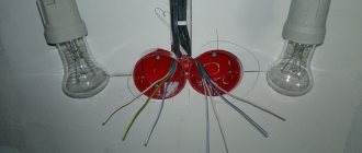
First, let's look at the design of the backlit switch. The operating principle is based on Ohm's laws. When lines with different resistances are connected in parallel, electric current flows along the path of least resistance.
Regardless of the indicator used (neon lamp or LED), the connection circuit has a high resistance. This is provided by a limiting resistor. The backlit switch circuit is shown in the illustration:
When contacts L and L1 are closed, the backlight unit is bypassed and current flows through the switch contacts. The main lamp lights up.
When the switch is opened, the lamp serves as a normal conductor. A small current flows through it, sufficient to operate the backlight. If an incandescent lamp is used, the spiral does not glow at such a meager current. But with housekeepers and LED lamps the same problem arises. The control circuit (the so-called driver) starts at a small current, which is provided by the backlight connection circuit.
If the parasitic glow does not bother you, the question: “how to connect a backlit switch” is not relevant. The scheme is no different from the usual one. Unless there are some nuances for the night illumination or operation indication modes. What does it mean? The indicator can light when the main lamp is turned off (night mode), or, on the contrary, signal that it is turned on. The second option is useful, for example, for lighting a bathroom or pantry, so as not to leave the lamp on.
How do dimmer buttons work?
Buttons on scenario-type dimmers open/close a circuit (electrical), and also reduce or increase the intensity and brightness of the lighting. These actions are performed by pressing them appropriately, in addition, the lighting in devices such as Legrand Celiane In-One (art. 067214) can also be controlled from the remote control.
How to connect backlit switches Legrand Etika 672403, 672203, 672303, 672603
look at the diagrams below.
Legrand Etika switch connection diagram in indication mode
(the lamp in the switch glows to indicate that the load is on).
Wiring diagram for Legrand Etika switch in night lighting mode
(the light in the switch helps to find the switch in the dark).
But first, we will provide diagrams that will help the customer (the owner of the house) understand the essence of the issue, and understand where, why and how he needs to install such switches.
Connections of “through” and “cross” switches are very simple, unless, of course, the “electrician” knows what “zero” and “phase” are.
An additional "crossover" switch is used.
Connection diagram for a pass-through switch for four or more control points:
This scheme differs from the previous one only in the number of control points.
Everything is very simple. You will have to run an additional cable between the switches.
Legrand switches connection diagrams
Switch 774301 (774401)
Illuminated switch 774310 (774410)
Double pole switch 774302 (774402)
Double switch 774305 (774405)
Control from 2 places (switch for 2 directions 774306 (774406))
Control from 2 places (2-way switch with backlight 774326 (774426))
Control from 2 places (2-way switch with indication 774325 (774425))
Control from 2 places of two groups of lamps (double switch for 2 directions 774308 (774408))
Control from three places (2 switches for 2 directions and an intermediate switch 7743 06+7743 07+7743 06 (7744 06+7744 07+7744 06))
Switch for controlling blinds 7743 04 (7744 04)
Push-button switch for controlling blinds 7743 14 (7744 14)
Options for using backlights
As an example, let's look at options for using backlights in Legrand products.
The backlight mode in the illustration is indicated by a picture of the month, the installation of a switch with an operation indication is indicated by a picture of a light bulb.
A single-key switch with night illumination is connected according to the classical scheme: a light bulb on contacts L. To indicate operation, a working zero must be set to the backlight lamp.
Connecting a two-key switch is done in the same way. Each operating line has a separate indicator light. The circuit provides separate indication of the double switch, each backlight works for its own line.
The three-key switch works exactly the same way. There will only be three indicators. By the way, this is another argument for opponents of the backlight: a three-key switch in display mode spends 3 times more energy than a double switch.
The pass-through switch can also work with backlight. Only the switching diagram will be different. The indicator is connected to those contacts that will be open when the key is in the “down” position. As a result, if you turn on the light with one of the “pass-throughs”, the backlight on it goes out.
When using the backlight as an indication of lamp operation, the indicator is connected to the lamp side, and a separate working zero is connected to it. Regardless of the position of the “feeders”, when the lighting is turned on, the indicator will light up.
Legrand sells backlight lamps separately. In essence, it is an ordinary LED with a quenching resistor and a freewheeling diode, packaged in a heat-shrinkable tube.
If you don’t want to overpay for the logo on the price tag, you can make a spare indicator yourself. The circuit is simple: in order to prevent reverse current from flowing through the LED element (we have alternating voltage in the network, the polarity changes with a frequency of 50 Hz), a reverse diode (type D226) is installed. And since the voltage drop across the LED is 2–3 volts (depending on the color), a current-limiting resistor is installed in the circuit. Diagram and part values in the illustration:
Any switch can be equipped with such an indicator, the main thing is that the light breaks through the plastic.
Read also: Machine for sewing gloves
We’ve figured out how to install a backlit switch, now we’ll deal with stray light. Cunning craftsmen are already offering for sale certain modules that are connected in parallel with housekeepers and LED lamps.
In fact, these are ordinary load resistors. They actually block unwanted light while using as much energy as a low-wattage incandescent lamp. That is, your lights are turned off, but the meter continues to wind.
To “make friends” between a backlit switch and LED (economical) lamps, you need a pass-through switch.
You connect a working lamp to one output, and an indicator with a separate working zero to the second. In this case, the phase works only for one consumer: either the main lamp or the indicator. In principle, there can be no parasitic glow.
Yes, the connection circuit is more complicated (you will have to draw the neutral wire). But you have to pay for the comfort of use. Electricity consumption is minimal, power no more than 1 watt.
Peculiarities
Let's take a closer look at what each switch from this company can boast of. To do this, you should consider the structure of this equipment. Like all switches, the Legrand product includes such elements as:
- The base on which all the parts are located and thanks to which they are attached to the wall or mounting box.
- Contacts and keys.
- Frame.
- Frame.
- Terminal blocks.
In order for the switch to be securely attached to the wall, the manufacturer makes its base from galvanized steel. The peculiarity of this base is that it is not deformable and has four special elongated holes for fastening. Fastening is carried out using screws. The shape of these holes makes it possible to adjust the position of the switch itself. That is, it can be tilted in different directions and centered.
This is very convenient when leveling it. Thanks to this base, the Legrand switch, which can be sold with a remote control, can be installed in any installation box. Depending on the model, the metal base may have some cutouts.
The main mechanism, the body of which is made of high-strength plastic, is attached to this plate. This plastic is polycarbonate. It is also used to create frames and keys.
A feature of most switches from this company is that the frames and key covers can be easily removed. To do this, the Legrand organization makes small grooves in them. A screwdriver is inserted into these grooves and used to remove the frame and key cover.
Helpful hint: mechanisms of the same series are the same and as a result, frames and keycaps with different colors can be used for the same mechanism.
This makes it possible not only to select the desired color at the connection stage, but also to change the color, as well as the appearance of the Legrand switch after a certain period of time.
Some series of switches provide for the use of frames that are made of porcelain, wood, and also covered with leather. As for the contacts, they are made of an element such as ArNi.
The advantage of this is that they do not contain cadmium. This element is known to cause contamination of contacts. As a result, their resistance increases and they begin to burn. Due to the absence of cadmium, Legrand switches are safer and last much longer.
We all clearly know that wires are connected to the switch. To make this connection very simple and, most importantly, reliable, the equipment is equipped with automatic terminals. All you have to do is strip the wire and insert it into these terminals.
It is noteworthy that in many models the terminals are placed at an angle of 35 degrees. And this simplifies the process of connecting wires. The terminals are quite durable and are designed for those copper and aluminum wires, the cross-section of which ranges from 1.5-4 square meters. millimeter.
Reverse side of the switch
It is worth noting that the professionalism of Legrand specialists did not stop there. On the back of the case they drew a special marker, which has a certain length and indicates how many millimeters of wire insulation need to be removed in order to make a quality connection.
In addition to the above-mentioned marker, Legrand specialists also put a connection diagram on the back of the switch, which also explains the principle of operation. Of course, this greatly simplifies the process of connecting the necessary wires.
Apparently, by applying such markings, the company takes care of those people who want to purchase, but do not know how to correctly install the Legrand switch; how to connect it is also a question to which they do not have an answer.
Another feature of many switch models from Legrand is that they can be equipped with a protection cover, backlight, dimmer, motion sensor, and also a microcircuit that can analyze remote control commands.
If we talk about backlighting, it is done using LEDs. They are very easy to replace. To do this, simply remove the key cover, pull out the unusable LED and insert a new one.
All the company's products are divided into series, they combine both one- and two-key switches. At the same time, many series have pass-through switches.
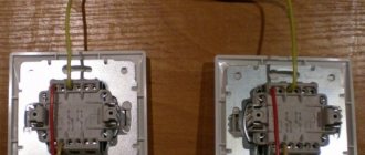
Preparatory work before installing the switch
To connect the light switch, preliminary preparations must be made. Installation is carried out from the nearest distribution box, to which power is supplied - network cables for supplying electric current.
Power to the switch and lamps is supplied from the distribution box
Three lines are laid - one from the junction box to the lamp, the other from it to the switch. The third one comes from the shield. As a rule, two- or three-core wires of the installation type are used, i.e., with a copper (or aluminum) conductor made of solid metal. In everyday life, such a wire is called hard, in contrast to soft, in which under the insulation there are pigtails of small hair conductors. On the marking, a rigid cable is designated by the letter “U”. The cross-sectional area of the conductor is selected in accordance with the load. For an ordinary lamp or chandelier, which combines up to 3 lamps, a wire with a cross-sectional area of 1.5 mm 2 is sufficient.
If energy-saving or LED light bulbs are used, the cross-section of the conductor can be reduced to 0.75 mm 2 in order to save money.
The type of wiring installation can be of two types - internal (hidden) and external. Hidden wiring is installed in the thickness of the wall or ceiling. The outer one runs along their surface, the cable is packaged in a corrugation or cable channel, which is attached to the wall with special brackets or other fastening material.
After the wires are separated, you can begin installing the switch.
Single-key switch connection diagram
The principle of operation of the switch is based on breaking the power supply circuit of a light bulb or any other device. Switching the toggle switch activates a contact pair, which disconnects the power wire from the current consumer.
The switch usually opens the phase wire
When assembling the circuit, you should pay attention to the reliability of the contacts. If the wires have large gaps, then at one point a so-called electric arc may occur, the temperature of which is sufficient to melt and ignite the insulation. This can lead to smoke in the living space and even a fire. In order to avoid such phenomena, the following connection methods are used:
- electrical terminal blocks. Connection with terminal blocks is especially recommended in cases where it is necessary to connect wires with cores made of different materials, for example, aluminum and copper;
When connected through the terminal block, strong, reliable contact is ensured, so the wires will never spark
The wires are twisted tightly using pliers and then soldered
Twisting of copper and aluminum wires is also possible. But if the connection is overloaded, aluminum can melt because it has a lower melting point than copper. The contact will be interrupted.
Tools and materials for connection
To connect you will need the following tools:
- Knife.
- Electrical screwdriver.
- Household voltage indicator.
- Pliers.
The materials on hand should be:
- Wires of the required length.
- Junction box.
- Terminal blocks or electrical tape.
- Lamp socket (and the lamp itself).
- Single key switch.
Photo gallery: materials for switch installation
Legrand company
Legrand Etika switch with 3 keys
The international company Legrand, whose headquarters is located in Limoges (France), was founded in 1866 and was initially engaged in the production of table porcelain. However, the company subsequently switched to the production of porcelain insulators (1904), and then focused on the production of electrical accessories (1949). Since then, continuously developing, the small enterprise has turned into a large international company with branches located in more than 60 countries around the world. Its enterprises produce a wide range of electrical products, from sockets to the creation of complex technical solutions for electrical and information networks.
Legrand is the only company that offers Russian enterprises and trade organizations a full range of electrical equipment developed taking into account the latest scientific and technical achievements and meeting the requirements of international standards.
Legrand products are fully certified for compliance with regulatory and technical documentation in force in Russia.
Step-by-step instructions for connecting a single-key switch
If all the tools and materials are ready, you can begin assembly. The procedure can be divided into two steps:
- connecting switch contacts and light bulbs;
- switching cables inside the junction box.
Before this, all wires are fixed in their designated places in cable ducts or corrugation. The distribution box and socket for the switch are firmly installed in (or on) the wall. The order of actions does not really matter, but experienced electricians always start connecting with the periphery - the switch and light bulb, and end with connecting the wires in the box.
Connecting the switch and lamp
- If the lamp is already connected, you can start with the switch. If not, connecting two wires to it will not be difficult. The cartridge has two connectors; one of the cable cores must be inserted into each and secured with a clamp screw.
Two wires are connected to the cartridge and fastened with screws to the corresponding contacts
When connecting wires to the switch and socket, the order in which the wires are connected does not matter
There are various models of switches, but in most cases they are mounted in a socket box using a spacer mechanism mounted on the base. Before attaching the base, you need to connect the wires to it. To do this, the screws of the clamps are loosened, the wires are inserted into the sockets, and the screws are clamped again. It is important not to overtighten the threaded fastener - you need to tighten it so as not to damage the screw slots.
If there is no socket box and the switch is attached externally, screw the base to the wall surface with two screws.
The external switch is installed directly on the wall surface
At this stage it needs to be positioned correctly. It is customary to install the switch so that turning off is done by pressing the button down, and turning on is done by pressing up. This is done for security reasons. If something accidentally falls on the switch from above, the mechanism will break the circuit and turn it off.
After screwing the screws into the wall and securing the base, the installation of the switch can be considered complete. All that remains is to insert the key into place, but this can be done at the very end, after checking the operation of the entire circuit.
Connecting cables in a junction box
Before connecting conductors, it is necessary to de-energize the line supplying electric current to the junction box. To do this, you need to turn off the plugs or the automatic breaker on the meter panel.
It is very convenient to carry out switching according to the color of the cores. Using a voltage indicator, you need to determine which core contains the phase and which contains the zero. Touching the phase wire will cause the diode on the probe to glow.
Read also: Phase black or blue
The indicator is activated by placing your finger on the red cap
Typically, the “phase” is connected to the red wire of the wire, “zero” to the blue, and “ground” to the white.
- The phase conductor is connected to one of the wires leading to the switch. This is necessary so that when the lamp is turned off, it is the “phase” that is interrupted, since it is this phase that poses the threat of electric shock.
- The second wire coming from the switch is connected to the red wire from the lamp. And the blue wire from the lamp is connected to the blue power wire coming from the electrical panel. Thus, the circuit is closed. Before testing the connection, turn the switch to the “Off” position, that is, press the down key. After this, the plugs (or machines) on the panel are turned on and the switch key is pressed. If everything works, you need to turn off the power to the circuit again and wrap the exposed connections with electrical tape. Carefully place the wires inside the box and close it with a lid.
- A key is installed on the switch. Assembly and connection are complete.
If everything works fine, you can assemble the switch and close the junction box
If the wiring in the house is made with three-core cables, all the white ground conductors are connected to each other.
Video: connection diagram for a single-key switch
Phase in the socket: left or right?
The existing opinion that the electrical voltage carrier in connectors is always on the left is not entirely correct. The arguments given are:
- Personal experience.
- Results of “ringing” of electrical cords and switches built into household appliances.
- Indicated in the specifications of gas boiler manufacturers.
- When you connect the plug to the connector with the “correct” side, you will get a cleaner sound.
All these arguments are far from reality. For a Euro socket of the Shuko type, it makes no difference at all how the wire is connected, since the connectors in Russia and other European countries do not have polarity. Only the connection standard CEE 7/5 has clear requirements for the sequence of connecting devices.
Electricians sometimes do not pay attention to the fact that the phase is located on the right. This is done for the sole purpose of making measurements easier to avoid confusion. Therefore, the phase in the socket is both on the left and on the right.
Is the phase in the socket located on the right or left? Source zen.yandex.ru
How to connect 3 sockets and 1 switch from one junction box
Sometimes you need to connect one or more additional sockets to the existing wiring. This can easily be done by running another cable into the junction box.
It should be noted that for sockets it is customary to use connecting wires with a larger cross-sectional area. This is due to the fact that a variety of household appliances are plugged into the outlet. This could be a kettle or, for example, a vacuum cleaner. Their power consumption is higher than that of a simple light bulb, and therefore the thin wires can heat up, which is undesirable. Therefore, sockets are connected with cables whose cross-section starts from 2.5 mm 2.
The connection process consists of connecting the wire to the power line that comes to the distribution box from the switchboard. As with the installation of the switch, all work should be carried out only with the plugs turned off.
- As in the first case, the sockets are first installed on the wall. Theoretically, you can install any number of sockets by connecting them together in parallel.
Special jumpers are used to connect sockets to each other.
The line of sockets is connected directly to the phase and neutral wires coming from the panel
When connecting wires using twists, it is advisable to thoroughly clean all contacts with a knife or fine file. Sometimes old wiring oxidizes at the connection points and the contact becomes unstable. When adding new wires, twisting is done using pliers.
To avoid a short circuit, the insulation must completely exclude possible contacts of wires with different poles.
Video: connecting a single-key switch and socket
Video
This video shows how to remove a socket from the wall in order to better secure it in the socket box:
Usually, disassembling a light switch in an apartment is required when it breaks, that is, to replace it with a new one. Some manufacturers, in order to improve the decorative effect of the element, make the holes for dismantling invisible, these are mainly brands: Legrand, Schneider, Viko. Because of this, a person who decides to do repairs may accidentally damage the case or spend a long time looking for clamps and connectors. The article will provide detailed instructions for removing the switch and socket.
How to connect a one-key switch to two light bulbs
If you need to turn on two light bulbs located in different places simultaneously from one switch, the same connection diagram is used.
The current supply to the lamps is controlled by a single switch, but the connection options for the lamps themselves may vary.
New cable in box
Another cable is inserted into the junction box. The ends of the conductors are stripped and connected to the same terminals as the first lamp. This will take up some additional space inside the box, but if there is enough space, then nothing bad will happen.
One way to connect two light bulbs to one switch is to connect both pairs of wires to the same terminals
Cable from an existing device
A tap is mounted from an existing lamp, which is connected to it in parallel. To do this, two additional contacts (“zero” and “phase”, red and blue) are inserted into the socket of the first lamp and extended to the second lamp.
The advantage of a parallel circuit for connecting lamps is the ability to use them in any quantity
The choice of connection is selected depending on the situation. The second option is used more often, since there is often not enough space in the distribution box to insert additional cables. In addition, in this way you can connect not only two lamps, but also a larger number of them. The main thing is to follow the principle of parallel connection of wires.
When installing household electrical equipment, you need to remember to comply with safety standards. Before starting work, be sure to turn off the power supply. It is better to use tools with dielectric coating and cables of the appropriate cross-section. Do not throw bare ends of conductors onto radiators or water pipes. In addition, the standard connection parameters must be observed.
Switches are mandatory attributes of each series of French electrical accessories - one of the leading manufacturers in the world market. They are comfortable, functional, durable, reliable and high quality, and also help shape office and living space, making it modern and attractive. Legrand offers a huge number of switches of various shapes and colors. They have various functions and capabilities.
Flaws
Such switches also have a number of disadvantages that must be taken into account during installation.
Let's highlight the main ones:
- If you don't know the main differences, they can easily be confused with a regular switch.
- There is no precise position to detect the position (on, off). For example, when replacing a light bulb, it is difficult to understand whether the power supply to the device is suitable or not. For safety, it is recommended to turn off the power supply.
- There are many wires appearing in the junction box. Their number increases with the number of light bulbs. It is not advisable to connect devices directly, because in this case you will have to endure high costs. In addition, with a large number of lamps in one circuit, the use of pulse relays is provided.
- Higher price due to design features.
What series of Legrand switches are offered to consumers?
Legrand Celiane These are premium switches. They are made in colors: white, graphite, titanium, ivory. These products are characterized by unusual stylish round shapes, sophistication of design and the ability to fit perfectly into even the most original and luxurious modern interior. They can be contactless, silent, touch, one- or two-key (with backlight or indication), switches-buttons or levers. Celiane switches are used as elements of a “Smart Home” (a high-tech control system for light, microclimate, etc.) and therefore represent unique equipment that has no analogues.
Legrand Valena This series of two- and one-gang switches and switches has a square classic shape and can be made in ivory, white, or aluminum colors. Many switch models are backlit. Products in this series will look decent in any design and are of excellent quality.
Legrand Valena Life The new series of switches has more rounded shapes than Legrand Valena. The switch key has a curved shape, which allows you to turn on the light with a light touch. Switches are available in white, ivory and aluminum colours. The modern design of Valena Life allows it to fit into any interior.
Legrand Valena Allure The innovative design of the Legrand Valena Allure series is a rejection of traditional forms. The curved lines of the series switches combine delicacy and novelty. Valena Allure switches are available in five colors: white, ivory, anthracite, aluminum and pearl.
Legrand Galea Life This series of switches is distinguished by its original colors (aluminium, dark bronze, mother-of-pearl, titanium, white), excellent quality and strict but attractive design. These are two- and one-key mechanisms. Many of them have backlighting and indication, and are also waterproof products.
Legrand Cariva These switches look attractive, have a fairly reasonable price and can look decent in both office and residential interiors. Types of mechanisms: two- and one-key, without and with backlight, waterproof, available in colors: “ivory”, “white”.
Read also: Solder for soldering copper melting point
Legrand Oteo This series of switches is intended exclusively for surface mounting. They are backlit and are offered to consumers as two- or single-key mechanisms. They are usually installed in rooms where exposed electrical wiring is carried out. Such switches are fire resistant, reliable and can be combined with products from other series.
Legrand Plexo These products are installed using both built-in and surface-mounted installation methods. Switches in this series have excellent moisture resistance and are presented on the market in the form of one- and two-key mechanisms with backlight and indication, as well as push-button switches. In most cases, they are used in production facilities and workshops/hangars with high humidity. Such switches can be either white or gray.
Legrand Mosaic These are the most high-tech switches that can be perfectly integrated with various Smart Home control elements. They have the function of controlling lighting from one or even two places, have backlighting (or are offered without it), and indication. Many models are contactless and operate with a specialized key or lanyard. Consumers are also offered switches for fans and switch buttons as part of this series.
Legrand Quteo These switches are used for surface mounting. They are used for installation in wooden rooms, balconies, verandas and other areas where hidden installation of wiring is difficult. Products are offered in both one- and two-key versions. These switches are available in woodgrain, white and ivory colours.
Legrand Anam This series differs from the previous ones in that it is presented in a range of one- to six-key switches inclusive. These products are available with or without backlighting and are available in ivory or white. They look original in any modern interior, especially in the spirit of minimalism or high-tech, and fit perfectly into modern offices and living spaces with modernist and technological notes in design.
Types of crossover and pass-through switches
Let's take a closer look at the subject of our interest. First, we will study the existing options, and then we will learn how to connect them to electrical wiring.
In appearance, changeover switches vary in color and shape, and they also come in:
- hidden or open installation;
- single-key, two-key, three-key;
- with or without backlight;
- a special character on the keys may or may not be present.
Considering the internal diagram, we can talk about the following types:
- Single-key pass-through switch. It is most often used as the first and last device in the case of 2 or more control points.
- Pass-through switch with two keys. A double device is used for the same purpose to control lighting using 2 groups of lamps.
- 3-key pass-through switch. Used for the same purpose to control three groups of lamps.
- Single-key cross or toggle switch. Used as an intermediate device in a chain of three or more locations.
- Two-key cross switch. Used as a middle device in a chain of 3, 4 or more control points for two groups of luminaires.
As follows from the illustration above, in a pass-through switch, the input terminal is connected to one of the output terminals when the key is pressed. In crossover - the conductors connected to the input and output change places when the position of the key changes.
There's no point in worrying about internal circuit diversity at this point. Firstly, most often only a single pass-through switch is in demand. Secondly, something else may be required, and this will become clear from the specific options for connecting devices.
The photo shows a rear view of the wiring accessories. Now you can choose and purchase the right model yourself. Unfortunately, not all manufacturers indicate the contact markings on the device body. If it is missing, you will have to use a multimeter to determine the placement of the product terminals.
What types of Legrand switches exist?
Based on the type of installation, these devices are divided into:
- Invoices. They are installed with the wiring open. These are the Quteo, Oteo, etc. series.
- Built-in. These devices are distinguished by a mechanism recessed into the wall surface and are used with appropriate wiring (hidden). At the moment, this is the main type of switches used in residential and office premises.
By type of on/off they can be:
- Keyboards. This is the most common type of switch. Today, they are equipped with a larger number of lighting systems in living rooms and office spaces. Moreover, devices consisting of two or more keys can control entire groups of lighting fixtures. At Legrand, such switches are presented in almost every series (Cariva, Quteo, Anam, Galea Life, etc.).
- Sensory. These are devices that use innovative technologies to control lighting. They work with a simple touch, and sometimes to turn on the light you just need to move your hand next to them (Celiane series, etc.).
- Equipped with IR sensors. Such switches have built-in devices that respond to movements and activate the lighting at the moment a person appears, and, accordingly, turn it off in the absence of people. Such devices are available in the Valena series and others.
- Push-button. These devices that control room lighting have not been used for very long, so they bring originality and freshness to every interior. They are quite convenient to use, but require some time to get used to (Celiane series, etc.).
Advantages
So, we have looked at the design features of the device for turning on lights from Legrand and now we can note what advantages they have. These advantages are:
- ease of use and installation;
- availability of additional functions;
- environmental friendliness;
- reliability;
- wide choice of external design.
As for the cons, the price is a little high for most models. However, it is quite justified, since it corresponds to the quality.
In the future, we will focus on the series of switches that are produced within the walls of the Legrand organization. So, she releases the following series:
What is the difference between Legrand switches with backlight and similar products with indication?
For example, let's take the Valena product (white) with backlight, art. 774410 and similar products of this series with indication, art. 774425.
In the first case, the lamp used for illumination is necessary to determine the location of the switch (for example, at night). It starts to glow when the switch is turned off.
The second product with an indication needs a lamp to determine the load. When the switch is in the inoperative position, it also does not function. In addition, the difference between these products is in the connection diagram. A conductor (phase) is inserted into electrical accessories with backlight for breaking. In a device with an indication, in addition to it, a neutral is carried out. The use of indication is convenient for working with remote types of loads that are beyond human vision (lighting in a barn, storage room, etc.).
Connecting switches
Two-gang switch
Model Celiane (white), art. 068002. It is assembled from two mechanisms (single-key). Installation mechanism:
- turn off the electricity;
- we prepare the wires for installation in the installation box;
- we connect two mechanisms in the caliper;
- we connect the wires to them (we use a system of 3 wires, first remove the insulation from them, and insert the phase into the terminal with the corresponding marking (L), and the other two (blue-yellow and blue) into the terminals with arrows responsible for their own key on the device);
- We fix the mounting box on the surface.
Pass-through switch
These switches are designed to control lights from different places. They allow you, while in one room, to turn it off/on in another place. Consider the Valena model (pass-through switch, art. 774306). It is connected together with its analogue through a box (distribution) with two output contacts. In this case, the neutral wire goes through it to the lamp, and the phase wire goes to the box, and then to the common contact of the pass-through switch. Unlike pass-through switches, crossover switches have not three, but four contacts (two of them are changeover) and can close and open each of the two lines.
What happens if you connect phase and zero?
When a phase and zero are connected, a short circuit occurs. Zero is the neutral of the transformer. This is the central point to which the beginnings of its 3 windings are connected at the transformer substation. The end of any of these 3 coils is a phase, between it and zero a potential difference of 220 V is formed, since the transformer is connected as a star. When a phase is connected to zero, the resistance becomes zero. The current tends to reach the maximum value that the transformer is capable of. Therefore, a short circuit occurs.
Why do energy-saving lamps flicker when connected to backlit switches?
The backlight lamps are connected in series with the load, so a small current from the backlight lamp also flows through the energy-saving lamp, causing it to turn on periodically. When a backlit switch (switch) and a compact fluorescent lamp work together, a problem arises that manifests itself in its periodic flashing when turned off. This is because the current flowing through the backlight element (neon lamp or LED) charges the capacitor and causes the lamp converter to spontaneously cycle. This problem can be solved using switches art. 067001 and backlight lamp art. 067686 (Celiane series), connected according to the diagram shown.