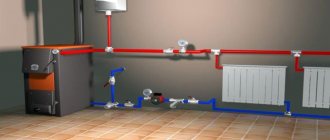
Supply and return in the heating system are separate systems designed to supply heated water to heating radiators and remove cooled liquid to the boiler or other heating equipment in order to further increase the temperature of the coolant. In what ways can you organize supply and return in modern conditions, read on.
Location of supply and return in the heating system
What should be the operating pressure in the heating system?
But to answer this question in a nutshell is quite simple.
Much depends on what kind of house you live in. For example, for an autonomous or apartment, 0.7-1.5 Atm is often considered normal. But again, these are approximate figures, since one boiler is designed to operate in a wider range, for example, 0.5-2.0 Atm, and the other in a smaller one. This must be looked at in the passport of your boiler. If there is none, stick to the golden mean - 1.5 Atm. The situation is completely different in those houses that are connected to central heating. In this case, it is necessary to be guided by the number of floors. In 9-story buildings, the ideal pressure is 5-7 Atm, and in high-rise buildings - 7-10 Atm. As for the pressure under which the carrier is supplied to buildings, most often it is 12 Atm. You can reduce the pressure using pressure regulators, and increase it by installing a circulation pump. The last option is extremely relevant for the upper floors of high-rise buildings. The advantage of using automatic balance valves is also the ability to divide the system into separate pressure-independent zones and carry out their phased commissioning. Benefits of automatic balance valves include easier and faster system setup, fewer valves, and minimal system maintenance. Modern automatic balance valves are characterized by high reliability and improved control characteristics. Some are modular in design, meaning they can be upgraded or expanded in functionality.
Boiler power
In a country house, rooms are heated using gas or electric equipment, less often - solid fuel models. Based on the size of the heated space, the power is calculated. For high-quality home heating you need 0.1 kW of thermal energy per square. Parameters may change due to climatic conditions or gentle regime up to 1.3.
The power of the boiler is affected by the material from which the walls are made and the presence of thermal insulation. Increased thermal conductivity, combined with the thinness of the partitions, increases the heat loss of a country house. Even the most efficient model will not cope with heating the building.
What to look for Source eco-kotly.ru
The quality of heating is affected by the presence of a second circuit in the boiler. When hot water is turned on for domestic needs, the performance in the utility system decreases. Designs with this option should have higher parameters than their single-circuit counterparts.
The boiler power depends on the type of fuel. Gas equipment is considered the most practical. The most expensive are electric, the most inconvenient are solid fuel. Pumps are used to optimize coolant circulation and solve the problem of air locks.
Where is the return route?
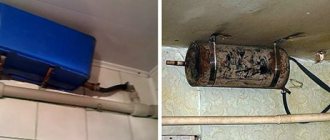
In short, the heating circuit consists of several important elements: a heating boiler, batteries and an expansion tank. In order for heat to flow through radiators, a coolant is needed: water or antifreeze. If the circuit is constructed correctly, the coolant heats up in the boiler, rises through the pipes, increasing its volume, and all excess ends up in the expansion tank.
Based on the fact that the batteries are filled with liquid, hot water displaces cold water, which, in turn, goes back into the boiler for subsequent heating. Gradually the water temperature increases and reaches the desired temperature. The coolant circulation can be natural or gravitational, carried out using pumps.
Based on this, the return can be considered a coolant that has passed through the entire circuit, giving off heat, and, already cooled, returned to the boiler for subsequent heating.
Differences between them
The difference between the described concepts is as follows:
- The supply is a coolant that flows through the radiators from the heat source.
- The return is a liquid that has passed through the entire circuit, and cooled down again to the heat source for subsequent heating. Therefore, occurs at the output .
- The difference is in temperature: the return is colder .
- The difference is in the installation. The water line that is attached to the top of the battery is the supply. What is attached to the bottom is the return line.
Important! Some tips need to be followed. The entire system must be completely filled with water or antifreeze . Maintaining fluid speed, circulation and pressure is equally important.
Temperature difference across radiators
The temperature difference should be 30 °C . In this case, the batteries will feel approximately the same to the touch . It is important to ensure that the difference in these values is not too large.
Photo 2. Heating diagram for 6 radiators: changes in flow and return temperatures on each of them are indicated.
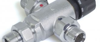
Pressure regulator
The operation of the batteries and the pump is disrupted due to high or low pressure levels. Correct control of the heating system will help to avoid this negative factor. The pressure in the system plays a significant role, it ensures that water gets into the pipes and radiators. Heat loss will be reduced if the pressure is standard and maintained. This is where water pressure regulators come to the rescue. Their mission is primarily to protect the system from too much pressure. The operating principle of this device is based on the fact that the heating system valve located in the regulator works as a force equalizer. Depending on the type of pressure, regulators are classified into: statistical, dynamic. It is necessary to select a pressure regulator based on throughput. This is the ability to pass the required volume of coolant, in the presence of the required constant pressure drop.
What to do if the radiators in the apartment are cold and the riser is hot?
Regardless of whether the cold heating equipment is only in the riser or in the entire entrance, and possibly throughout the house, you must seek help from qualified specialists.
In the case of an apartment building, this is a plumber of the company that is responsible for the heating supply of the house. Cold batteries with a hot riser may be due to a clogged system or the formation of an air lock in it. An important factor is the pressure in the wiring. In some cases, the problem of low coolant flow is relevant. It is possible to independently find out the reason for the low efficiency of heating elements. But only a true professional in his field will clearly answer any questions that arise and competently fix the breakdown. This video will help you to make your radiators heat better:
Often, residents of both apartment buildings and private houses are faced with the problem of cold radiators. In this article we will explain why this problem occurs and what to do if the batteries are cold.
Operating pressure in the heating system
Working pressure is considered to be the pressure whose value ensures optimal operation of all heating equipment (including the heating source, pump, expansion tank). In this case, it is taken equal to the sum of pressures:
- static - created by a column of water in the system (in calculations the ratio is taken: 1 atmosphere (0.1 MPa) per 10 meters);
- dynamic - due to the operation of the circulation pump and the convective movement of the coolant when it is heated.
It is clear that in different heating schemes the operating pressure will differ. So, if natural circulation of the coolant is provided for heating the house (applicable for individual low-rise construction), its value will exceed the static value by only a small amount. In forced schemes, it is taken as maximum permissible to ensure higher efficiency.
Numerically, the working pressure is:
- for one-story buildings with an open layout and natural circulation of water – 0.1 MPa (1 atmosphere) for every 10 m of liquid column;
- for low-rise buildings with a closed layout - 0.2-0.4 MPa;
- for multi-storey buildings - up to 1 MPa.
Application example: two-pipe system with circulation pump, total power 18 kW.
The wiring is made with a polypropylene pipe, symbol - PP.
As we can see from the diagram, first a polypropylene pipe with a diameter of 40 mm comes out of the boiler, its internal clearance is 25 mm, which corresponds to a metal VGP pipe of 1 inch (25 mm). Next comes the outlet for the boiler (4 kW) and heated floors (2 kW) of two PP pipes with a diameter of 16 mm. After this, part of the coolant separated, so there is no need for such a thick pipe. A thinner pipe will be used for heating the 1st and 2nd floors - 32mm, it will go to the first tee. At the tee, a branch is separated to the 1st floor, with a diameter of 25 mm, and to the 2nd floor, also with a diameter of 25 mm. A polypropylene pipe with a diameter of 16 mm is already suitable for the final radiators. And on the last 3 radiators the supply pipe is also narrowed to 16mm.
In a one-pipe system, unlike a two-pipe system, the entire coolant of the system is supplied through one pipeline. Therefore, in such a system, the entire pipeline (after branching the pipe to the boiler and heated floor) will have a diameter of 32 mm, and 16 mm pipes will be suitable for individual radiators from the main pipeline.
In the article we will consider systems with forced circulation. In them, the movement of the coolant is ensured by a constantly running circulation pump. When choosing the diameter of heating pipes, it is assumed that their main task is to ensure the delivery of the required amount of heat to heating devices - radiators or registers. For the calculation you will need the following data:
- General heat loss of a house or apartment.
- The power of heating devices (radiators) in each room.
- Pipeline length.
- Method of wiring the system (one-pipe, two-pipe, with forced or natural circulation).
That is, before you start calculating the diameters of the pipes, you first calculate the total heat loss, determine the power of the boiler and calculate the power of the radiators for each room. You will also need to decide on the wiring method. Using these data, you draw up a diagram and then just start calculating.
To determine the diameter of the heating pipes, you will need a diagram with the thermal load values assigned to each element.
What else do you need to pay attention to? The fact is that the outer diameter of polypropylene and copper pipes is marked, and the inner diameter is calculated (subtract the wall thickness). For steel and metal-plastic ones, the internal size is indicated when marking. So don't forget this little thing.
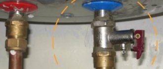
Safety valves
Any boiler equipment is a source of danger. Boilers are considered explosive because they have a water jacket, i.e. pressure vessel. One of the most reliable and widespread safety devices that reduces the danger to a minimum is the safety valve of the heating system. The installation of this device is due to the protection of heating systems from excess pressure. Often this pressure occurs as a result of boiling water in the boiler. The safety valve is installed on the supply pipe, as close to the boiler as possible. The valve has a fairly simple design. The body is made of good quality brass. The main working element of the valve is the spring. The spring, in turn, acts on the membrane, which closes the passage to the outside. The membrane is made of polymer materials, the spring is made of steel. When choosing a safety valve, it should be taken into account that full opening occurs when the pressure in the heating system increases above the value by 10%, and full closure occurs when the pressure drops below the response value by 20%. Due to these characteristics, it is necessary to select a valve with a response pressure higher than 20-30% of the actual one.
How to make radiators hot - looking for solutions
If you find that the return is too cold, you should take a number of steps to find the causes and troubleshoot problems. First of all, you need to check that the connection is correct. If the connection is not made correctly, the down pipe will be hot when it should be slightly warm. The pipes should be connected according to the diagram.
To avoid air pockets that impede the flow of coolant, it is necessary to provide for the installation of a Mayevsky valve or bleeder for air removal. Before bleeding the air, you need to turn off the supply, open the tap and let out the air. Then the tap is turned off and the heating valves open.
Often the cause of cold return is the control valve: the cross-section is narrowed. In this case, the tap must be dismantled and the cross-section increased using a special tool. But it is better to buy a new faucet and replace it.
The reason may be clogged pipes. You need to check them for passability, remove dirt and deposits, and clean them well. If passability cannot be restored, the clogged areas should be replaced with new ones.
If the coolant flow rate is insufficient, you need to check whether there is a circulation pump and whether it meets the power requirements. If it is missing, it is advisable to install it, and if there is a lack of power, replace or upgrade it.
Knowing the reasons why heating may not work efficiently, you can independently identify and eliminate malfunctions. Comfort in the house during the cold season depends on the quality of heating. If you carry out the installation work yourself, you can save on hiring third-party labor.
Economical energy consumption in the heating system can be achieved if certain requirements are met. One option is to have a temperature diagram, which reflects the ratio of the temperature emanating from the heating source to the external environment. The values of the values make it possible to optimally distribute heat and hot water to the consumer.
High-rise buildings are mainly connected to central heating. The sources that transmit thermal energy are boiler houses or thermal power plants. Water is used as a coolant. It is heated to a given temperature.
Having gone through a full cycle through the system, the coolant, already cooled, returns to the source and reheats. Sources are connected to consumers by heating networks. Since the environment changes temperature, thermal energy should be adjusted so that the consumer receives the required volume.
Heat regulation from the central system can be done in two ways:
- Quantitative.
In this form, the water flow changes, but its temperature remains constant. - Qualitative.
The temperature of the liquid changes, but its flow does not change.
In our systems, the second regulation option is used, that is, qualitative. Here there is a direct relationship between two temperatures:
coolant and environment. And the calculation is carried out in such a way as to ensure the heat in the room is 18 degrees and above.
Hence, we can say that the temperature graph of the source is a broken curve. The change in its directions depends on temperature differences (coolant and outside air).
The dependency schedule may vary.
A specific diagram has a dependency on:
- Technical and economic indicators.
- CHP or boiler room equipment.
- Climate.
High coolant values provide the consumer with great thermal energy.
Below is an example of a diagram, where T1 is the coolant temperature, Tnv is the outside air:
A diagram of the returned coolant is also used. A boiler house or thermal power plant can estimate the efficiency of the source using this scheme. It is considered high when the returned liquid arrives chilled.
The stability of the scheme depends on the design values of fluid flow of high-rise buildings.
If the flow through the heating circuit increases, the water will return uncooled, as the flow rate will increase. Conversely, with minimal flow, the return water will be sufficiently cooled.
The supplier's interest, of course, is in the supply of return water in a cooled state. But there are certain limits for reducing consumption, since a decrease leads to loss of heat. The consumer’s internal temperature in the apartment will begin to drop, which will lead to violation of building codes and discomfort for ordinary people.
Features of the heating system of apartment buildings
When installing heating in multi-storey buildings, it is imperative to comply with the requirements established by regulatory documentation, which include SNiP and GOST. These documents indicate that the heating structure must ensure a constant temperature in the apartments within 20-22 degrees, and humidity must vary from 30 to 45 percent.
To achieve the required parameters, a complex design is used, requiring high-quality equipment. When creating a project for the heating system of an apartment building, specialists use all their knowledge to achieve uniform heat distribution in all sections of the heating main and create comparable pressure on each tier of the building. One of the integral elements of the operation of such a design is operation on a superheated coolant, which provides for the heating scheme of a three-story building or other high-rise buildings.
How it works? The water comes directly from the thermal power plant and is heated to 130-150 degrees. In addition, the pressure is increased to 6-10 atmospheres, so the formation of steam is impossible - high pressure will drive water through all floors of the house without loss. The temperature of the liquid in the return pipeline in this case can reach 60-70 degrees. Of course, at different times of the year the temperature regime may change, since it is directly related to the ambient temperature.
Penalty for excess return flow Blog of a heating engineer
Hello, dear readers of the blog teplosniks.ru! On my blog I previously wrote about overheating of the heating return. The most unpleasant thing in such a situation is when you are given a specific bill for overheating in the return pipeline. No one wants to part with money, especially when the volume of heat consumption is calculated in the form of penalties. You have to pay the meter and more. So, how exactly does the energy supply organization calculate the fine?
The first point determines the contractual flow of network water through the heating unit. It is determined by the formula:
where Qdog is the heat load for heating under the contract (this figure must be in the contract, look). Let's take a specific figure of 0.332 Gcal/hour.
C—heat capacity of water, kcal/kg °C
t1 — supply temperature according to schedule, °C
t2 — return temperature according to schedule, °C
We substitute specific numbers. Usually the temperature graph is 150/70 °C (but it can also be 130/70 °C and 105/70 °C, etc.). In our case t1 = 150°С; t2 = 70°C. The heat capacity of water can be taken to be unity, C = 1. In fact, the heat capacity will be slightly different from unity, but we don’t need such super-precision. So, we calculate the figure, the consumption of network water, which should be according to the contract.
Gdog = 0.332*1000 /(150-70)*1 = 4.15 t/hour.
We have the water consumption according to the contractual load that must pass through your heating unit. The actual consumption (according to the meter printout) should not exceed the contractual one. If it exceeds, it means you are overheating. In order to count further, you need a printout from the heat meter. The printout looks like this.
This is a printout from the KM-5 heat meter. I give it only as an example. Your metering device can be any other one, not necessarily KM-5. But the essence of the matter does not change, in any printout, from any heat meter, the main figures are heat consumption Q in Gcal and temperatures t1 and t2, in °C. Using this very printout, we need to calculate the actual water flow through the heating unit. It is calculated according to the same formula:
Gfact = Qfact*1000 ⁄(t1fact-t2fact)*C.
We look at your printout of the supply and return temperatures t1 and t2. Let t1 = 73.1 °C, t2 = 49.5 °C. We also look at the amount of heat Qfact from the printout, let this figure be 101.4 Gcal. We divide the number of Gcal per month by the number of hours in the month, 101.4 Gcal per 720 hours, we get 0.141 Gcal/hour. Let's count further:
Gfact = 0.141*1000 ⁄(73.1-49.5)*1 = 5.97 t/hour.
At t1 = 73.1 °C, return according to the schedule is 43.8 °C. In fact, here we have 49.5 °C. Overheating 49.5-43.8 = 5.7 °C. If expressed as a percentage, then it was overheated by 13.01%. Accordingly, such overheating gave us an excess of actual consumption over the calculated G exceeded. = 5.97-4.15 = 1.82 t/hour. Now you can calculate specifically how many Gcal penalties the heat supply organization will charge you.
It is calculated by the formula:
Qfine = Gexceed*С*(t2actual-t2 permissible excess according to schedule)*number of hours per month*0.001.
We calculate the permissible excess of t2 according to the 5% schedule as follows: take t2, which should be at t1 = 73.1 °C, according to the schedule - 43.8 °C and multiply by 1.05 we get 45.99 °C. Let's calculate how much we will be charged for overheating:
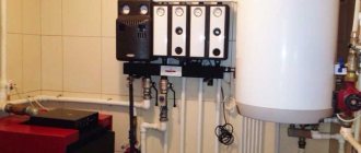
Design features of the heating circuit
Modern buildings often use additional elements, such as collectors, heat meters for batteries and other equipment. In recent years, almost every heating system in high-rise buildings has been equipped with automation to minimize human intervention in the operation of the structure (read: “Weather-dependent automation of heating systems - about automation and controllers for boilers using examples”). All the described details allow you to achieve better performance, increase efficiency and make it possible to more evenly distribute thermal energy throughout all apartments.
Operating principle of water heating
The system is a closed loop in which the coolant circulates through pipes from the boiler to the radiators.
Cooling down, the water again enters the boiler, and the cycle is repeated many times.
Water is often used as a coolant, and antifreeze is used less often. The first option is more profitable, and the second is safer, since the systems will not shrink in harsh winters.
The heating operation is regulated by additional devices, which include an expansion tank, pressure gauges, safety valves, and shut-off valves.
Pipelines are used to create a closed circuit
When choosing pipes, you need to pay attention to the material of manufacture. Popular options are galvanized or stainless steel, copper, polymers
Reference! Metal-plastic pipes are most often chosen. The products are durable, non-corrosive and durable. The inner walls of such pipelines are smooth, do not become overgrown with scale and scale, and therefore do not lose their properties over time.
Natural and forced water circulation
Water circulation is ensured by natural gravitational processes or special pumps (forced circulation).
Gravity systems are beneficial in arrangement and operation.
It does not require additional equipment, and there is no noise during operation. The heated water rises up and is distributed over the radiators, and the cooled water falls and goes to the boiler.
The movement of the coolant does not depend on the energy supply, so during periods of power outages the house remains warm.
To design and install a system with natural water circulation, no special skills are required. It is enough to think through the scheme and maintain the necessary slopes.
Such heating can operate uninterruptedly for 30–35 years. The most that may be required is minor repairs.
Important! Heating with natural circulation of water has a significant disadvantage: the system is effective if a two-pipe system is installed. When there is only one circuit, the radiators heat up unevenly and each subsequent one is colder than the previous one
When saving on equipment, you have to overpay for pipes and components.
For forced circulation of coolant, pumps are installed.
Such systems are more efficient because hot water quickly flows to the radiators, without having time to cool in the pipeline.
The heating works perfectly, regardless of which scheme is chosen - one- or two-pipe. However, when the power goes out, the heating stops and the house quickly cools down.
A compromise option is a well-thought-out scheme that provides for natural and forced circulation at the same time. When there is a power outage, the heating is simply switched to gravity mode, bypassing the pump.
One- and two-pipe, manifold wiring
Depending on the specifics of the coolant movement and the principle of operation, a single-pipe, two-pipe, or collector system is distinguished. Each of the schemes has its own advantages:
Single-pipe. This is a standard scheme in which the system resistance increases with distance from the boiler, which leads to uneven heating of the radiators. To solve the problem, use balancing fittings.
Photo 2. Single-pipe heating system with boiler, radiators, expansion tank, circulation pump.
- Two-pipe. The scheme provides two pipes - supply and return. The coolant from the boiler is supplied to all radiators in the circuit, due to which they are evenly heated. Two-pipe wiring is convenient, practical, but metal-intensive, and therefore requires serious installation costs.
- Collector (radial). This is an ideal option in terms of performance and hydraulic stability. To adjust the operating technology of radiators, a cabinet is installed where the collectors and all shut-off and balancing valves are placed. If necessary, one or more radiators are turned off without damaging other devices.
Types of heating systems
The amount of heat that the heating radiator will emit depends not least on the type of heating system and the selected type of connection. To choose the best option, you must first understand what kind of heating systems there are and how they differ.
Monotube
A single-pipe heating system is the most economical option in terms of installation costs. Therefore, this type of wiring is preferred in multi-storey buildings, although in private buildings such a system is far from uncommon. With this scheme, the radiators are connected to the main line in series and the coolant first passes through one heating outlet, then enters the input of the second, and so on. The output of the last radiator is connected to the input of the heating boiler or to the riser in high-rise buildings.
Example of a one-pipe system
The disadvantage of this wiring method is the impossibility of adjusting the heat transfer of radiators. By installing a regulator on any of the radiators, you will regulate the rest of the system. The second significant drawback is the different coolant temperatures on different radiators. Those that are closer to the boiler heat up very well, those that are further away become increasingly colder. This is a consequence of the serial connection of heating radiators.
Two-pipe wiring
A two-pipe heating system is distinguished by the fact that it has two pipelines - supply and return. Each radiator is connected to both, that is, it turns out that all radiators are connected to the system in parallel. This is good because the coolant of the same temperature enters the input of each of them. The second positive point is that you can install a thermostat on each of the radiators and use it to change the amount of heat it emits.
The disadvantage of such a system is that the number of pipes when laying out the system is almost twice as large. But the system can be easily balanced.
Radiator connection diagrams
How well the radiators will heat depends on how the coolant is supplied to them. There are more and less effective options.
Radiators with bottom connection
All heating radiators have two types of connection - side and bottom. There can be no discrepancies with the bottom connection. There are only two pipes - inlet and outlet. Accordingly, coolant is supplied to the radiator on one side and removed from the other.
Bottom connection of heating radiators for single-pipe and two-pipe heating systems
Specifically, where to connect the supply and where the return is connected is written in the installation instructions, which must be available.
Heating radiators with side connection
With a lateral connection, there are many more options: here the supply and return pipelines can be connected into two pipes, respectively, there are four options.
How to correct the situation when there is a drop
Everything here is extremely simple. First, you need to look at the pressure gauge, which has several characteristic zones. If the arrow is in the green, then everything is fine, but if it is noticed that the pressure in the heating system is dropping, then the indicator will be in the white zone. There is also a red one, it signals an increase. In most cases, you can handle it on your own. First you need to find two valves. One of them is used for injection, the second is used for bleeding media from the system. Then everything is simple and clear. If there is a shortage of media in the system, it is necessary to open the discharge valve and monitor the pressure gauge installed on the boiler. When the arrow reaches the required value, close the valve. If bleeding is needed, everything is done in the same way with the only difference being that you need to take with you a vessel into which the water from the system will be drained. When the pressure gauge needle shows normal, tighten the valve. Often this is how the pressure drop in the heating system is “treated”. Now let's move on.
They are widely used in constant flow systems. The main advantage of manual balance valves is their low cost. The main disadvantage is that every change in the installation must rebuild the system, which is labor-intensive and expensive.
Automatic balance valves Automatic balance valves allow you to flexibly change the parameters of the pipeline system depending on fluctuations in pressure and flow of the working medium. They are proportional regulators that maintain a constant differential pressure in the system and minimize disturbances caused by control valves. They are characterized by high performance, which allows them to maintain the established hydraulic conditions in systems, compensating for interference caused by the control valve.
Consumer choice: cast iron or aluminum
The aesthetics of cast iron radiators is the talk of the town. They require periodic painting, since the rules require that the working surface have a smooth surface and allow dust and dirt to be easily removed.
A dirty coating forms on the rough inner surface of the sections, which reduces the heat transfer of the device. But the technical parameters of cast iron products are excellent:
- are slightly susceptible to water corrosion and can be used for more than 45 years;
- have high thermal power per section, therefore they are compact;
- are inert in heat transfer, so they smooth out temperature changes in the room well.
Another type of radiator is made of aluminum. Lightweight, factory-painted design, does not require painting, and is easy to maintain.
But there is a drawback that overshadows the advantages - corrosion in an aquatic environment. Of course, the inner surface of the heater is insulated with plastic to avoid contact of aluminum with water. But the film may be damaged, then a chemical reaction will begin with the release of hydrogen, and when excess gas pressure is created, the aluminum device may burst.
The temperature standards for heating radiators are subject to the same rules as batteries: it is not so much the heating of a metal object that is important, but the heating of the air in the room.
In order for the air to warm up well, there must be sufficient heat removal from the working surface of the heating structure. Therefore, it is strictly not recommended to increase the aesthetics of the room with shields in front of the heating device.
Pressure norm
Effective transfer and uniform distribution of coolant for the performance of the entire system with minimal heat loss is possible at normal operating pressure in the pipe lines.
The coolant pressure in the system is divided according to the method of action into types:
- Static. The force of influence of a stationary coolant per unit area.
- Dynamic. Force of action during movement.
- Maximum pressure. Corresponds to the optimal value of liquid pressure in the pipes and is capable of maintaining the operation of all heating devices at a normal level.
According to SNiP, the optimal indicator is 8-9.5 atm, reducing the pressure to 5-5.5 atm. often leads to heating interruptions.
For each specific home, the normal pressure indicator is individual. Its value is influenced by factors:
- power of the pumping system supplying coolant;
- pipeline diameter;
- remoteness of the room from the boiler equipment;
- wear of parts;
- pressure
Pressure control is possible using pressure gauges mounted directly into the pipeline.
What is needed for this
To calculate the diameter of the pipe, as a rule, the following factors are taken into account:
- Total heat loss of the home.
- What power do heating radiators have separately in each room.
- The total length of the circuit pipes.
- How is the system wired?
To be able to calculate the diameter of the pipes, it is necessary to determine in advance the total heat loss, the power of the boiler equipment and batteries for each room. It is also important which method will be chosen for pipe routing. Having all these parameters in hand, a future calculation scheme is drawn up.
It is also important to remember some of the specific markings of different pipes. Thus, on polypropylene pipes for heating a private house, the outer diameter is indicated (the same applies to copper products). To calculate the internal parameter, the wall thickness is subtracted from this indicator. Steel and metal-plastic pipes are marked by their internal cross-section.
Pipe diameter and degree of wear
It is necessary to remember that the size of the pipe must also be taken into account. Often, residents set the diameter they need, which is almost always slightly larger than the standard sizes. This leads to the fact that the pressure in the system decreases slightly, which is due to the large amount of coolant that will fit into the system. Do not forget that in corner rooms the pressure in the pipes is always less, since this is the most remote point of the pipeline. The degree of wear of pipes and radiators also influences the pressure in the heating system of the house. As practice shows, the older the batteries, the worse. Of course, not everyone can change them every 5-10 years, and it is not advisable to do this, but it doesn’t hurt to carry out preventive maintenance from time to time. If you are moving to a new place of residence and you know that the heating system there is old, then it is better to change it immediately, so you will avoid many troubles.
Hydraulic balance of hot water supply systems. The hot water temperature in hot water systems drops significantly when demand is low or absent. This leads to several problems: long waits for hot water, water overflow, and the possibility of unwanted bacteria developing. To maintain the water temperature at the required level, this is usually a constant circulation of water in the systems, through a circulation pump and a circulation pipe. Hydraulic balance in these systems is usually maintained using direct acting temperature controllers.
Comparison results
Summing up, it becomes clear that a single-pipe distribution system with a return has the greatest prospects , especially for multi-storey buildings. Ease of installation, low cost and a small number of communications still have an advantage over a two-pipe with supply.
However, do not forget that using a two-pipe circuit, it is possible to regulate the heating temperature for each device separately.
Vadim – Plumber 4 category Plumbing work, Installation of heating radiator 01/24/2018
Many users of our site are looking for information about how Kermi radiators are connected, and what kind of jumper or so-called bypass they have inside, which is a tube originating below the supply connection itself (as Kermi knows, it is from below). From this lower connection pipe, the tube inside the radiator rises and is adjacent to the tap, with the help of which the supply of coolant is regulated.
Well, due to this tube, proper thermosiphon circulation of the coolant inside the radiator occurs. This was also done to conveniently adjust the temperature in the coolant supply radiator. Due to this, from such radiators it is possible to build a radiator branch up to fifty meters in length on the principle of natural circulation (without pumping) natural - gravitational or thermosiphon circulation of the coolant will pump itself. This distinguishes regular radiators with a bottom connection from a conventional radiator connected at the bottom – bottom in the picture below.
In the figure we see a regular - sectional radiator that does not have a tube inside it, a tube that would lift the coolant up from where it would be pressed into them as it cools, so a regular sectional radiator for its natural circulation must be connected top - bottom diagonally - this is mandatory and very reliable connection that should be used for natural circulation. And in the case when a conventional sectional radiator is connected to the bottom, it needs to be pumped using forced hydraulics and it will always become airy.
But this is a fixable problem, and if you really want, you can depict the bottom and bottom of a regular panel radiator.. To do this, you need to buy a flow distributor - do not confuse it with an extension cord. A flow distributor is just such a thing.
It is needed in order to use a gasket supported by a spring to plug the intersectional flow inside the battery between the first and second sections, then the heat flow will have to rise upward and this is the same as the tube for radiators with a bottom connection, or it’s the same as a diagonal connection when the inlet is at the top and the outlet from below on the opposite side. But let’s return to the Kermi radiators, their bottom connection and bypass connector.
Connectors for Kermi radiators with a standard axial distance of 50 mm - which corresponds to the standard interaxial size of most radiators with bottom connections, unlike Rifar Monolith, but not about that now.. That means - connectors for fucking batteries with bottom connections are straight and at an angle of 90 degrees so that the liner goes into the wall. And with straight connectors, the liner will be hidden in the floor.
This is a direct connector for laying pipes of the heating branch under the floor.
And this is a corner connector for laying a heating main inside the wall.
The standard bypasses for all radiators with bottom connections look something like this, only “Rifar Monolit” has its own standard, which is wider than usual and the distance along the axes is not 50 mm but 80 mm.
Are all these expensive bypasses really necessary? In principle, they are not needed and can be completely dispensed with. For example, connect the radiator like this - directly.
If there are special requirements for aesthetics and even if the pipes will be laid inside the walls, then it is recommended to install corner connectors.
Vadim – Plumber 4th category
We work from 8 to 22
Plumber for an hour
Cost of work from 800 rubles
Plumber specialist
Call cost from 2000 rubles
Where to put radiators
Traditionally, heating radiators are placed under windows, and this is no accident. The rising flow of warm air cuts off the cold air that comes from the windows. In addition, warm air heats the glass, preventing condensation from forming on it. Only for this it is necessary that the radiator occupies at least 70% of the width of the window opening. This is the only way the window will not fog up. Therefore, when choosing the power of radiators, select it so that the width of the entire heating battery is not less than the specified value.
How to place a radiator under a window
In addition, it is necessary to correctly select the height of the radiator and the location for its placement under the window. It must be placed so that the distance to the floor is around 8-12 cm. If you lower it lower, it will be inconvenient to clean, if you raise it higher, your feet will be cold. The distance to the window sill is also regulated - it should be 10-12 cm. In this case, warm air will freely go around the obstacle - the window sill - and rise along the window glass.
And the last distance that must be maintained when connecting heating radiators is the distance to the wall. It should be 3-5 cm. In this case, rising currents of warm air will rise along the back wall of the radiator, and the rate of heating the room will improve.
Radiator does not heat up
Most often, problems with normal heat transfer occur in heating radiators. This is explained by their specific design - the coolant does not move through one pipe, as in a transport line, but is distributed over several.
In what cases does the heating radiator not heat? There are several factors that directly affect the correct operation of the battery.
Air locks in heating
There are several reasons for the appearance of air locks in the heating system - excess temperature, water evaporation, etc.
It is important that the consequence of this is the appearance of places in the line that are not filled with coolant. Most often these are heating radiators. To eliminate them, it is necessary to install a Mayevsky valve - an air valve that releases excess air from the device
To eliminate them, it is necessary to install a Mayevsky valve - an air valve that releases excess air from the device.
How to determine why a radiator does not heat well? The simplest method is a temperature difference on the surface. At the point where the air lock forms, it will be significantly lower, thereby preventing the normal passage of the coolant. To eliminate it, you must perform the following steps:
- Using a screwdriver or a rotary lever, the Mayevsky tap is opened;
- Add water to the system until the coolant begins to flow out of the tap along with the air;
- Shut off the water supply.
After starting the heating system, the surface of the radiator should heat evenly. Otherwise, repeat the procedure.
Improper installation and limescale deposits in pipes
The efficiency of its operation depends on the correct installation of the radiator. It should not be inclined relative to the plane of the floor and wall. If this condition has not been met, then the question will inevitably arise - why the heating battery does not heat.
To check the correct installation of the radiator, you can take a standard building level. If the upper plane of the battery has deviations, re-installation should be performed. It is best to use new reinforced fasteners for this.
If after this the question of why the heating radiator does not heat remains unresolved, it is recommended to flush the heating system. This problem is relevant for old pipes and radiators made of steel and cast iron. Over time, a limescale layer accumulates on the inner surface, preventing the normal flow of coolant. There are several ways to perform the washing procedure:
- Hydraulic. A special pump is connected to the system circuit, which creates high water pressure. Under the influence of this force, the scale is broken into small fractions and retained in the pump filter;
- Chemical. Special additives act on limescale, which loses its uniformity and flakes off from the inner surface. Subsequently, hydraulic flushing is performed to remove residual debris.
Experts recommend using a comprehensive method to solve the problem in which the radiator does not heat up. After checking the correct installation, the system is flushed, and then filled correctly with the Mayevsky tap open.
If a two-pipe heating system does not heat due to clogged pipes, you need to carefully choose a cleaning technology. For pipelines made of polypropylene, chemical cleaning cannot be done.
About Leak Testing
It is imperative to check the system for leaks. This is done to ensure that the heating operation is efficient and does not have failures. In multi-storey buildings with central heating, the cold water test is most often used. In this case, if the heating system drops by more than 0.06 MPa in 30 minutes or 0.02 MPa is lost in 120 minutes, it is necessary to look for places where there are gusts. If the indicators do not go beyond the norm, then you can start the system and begin the heating season. Hot water testing is carried out immediately before the heating season. In this case, the media is supplied under pressure, which is the maximum for the equipment.
Their purpose is to maintain temperature and minimize water consumption in hot water circulation systems
An important feature of these valves is the presence of periodic disinfection of the DHW pipeline network. Tags: balancing valves Manual balancing valves
Autonomous heating systems
Today you may not ask for cold, but your heating system will do it for you. If you did not pay enough attention during the summer season, an unpleasant surprise can be expected at the beginning or during the heating season. Do you have a cold house because your radiators are as bad as ever before? Errors in maintenance or poor adjustment of some parts of your heating system may be a malfunction. It's best to use the summer months to maintain your heating system, but many people will only start doing it when they need to flood for the first time.
What types of thermostatic radiator heads are there?
Thermostatic heads are of the following types:
- manual;
- mechanical;
- electronic.
They have the same purpose, but the user properties are different:
- Manual devices operate on the principle of conventional valves. When you turn the regulator in one direction or another, the coolant flow opens or closes. Such a system will not be expensive, it is reliable, but not very comfortable. To change the heat transfer, you must adjust the head yourself.
- Mechanical ones are more complex in design; they can maintain the desired temperature in a given mode. The device is based on a bellows filled with gas or liquid. When heated, the temperature agent expands, the cylinder increases in volume and presses on the rod, increasingly blocking the coolant passage channel. Thus, less coolant passes into the radiator. When the gas or liquid cools, the bellows decreases, the rod opens slightly, and a larger volume of coolant flow rushes into the radiator. A mechanical thermostat for a heating radiator is quite convenient to use and popular among consumers due to its ease of maintenance.
- Electronic thermostats are large in size. In addition to massive thermostatic elements, they come with two batteries. The rod is controlled by a microprocessor. The models have quite a lot of functionality. You can set the temperature in the room for a certain time. For example, the bedroom will be cooler at night and warmer in the morning. During those hours when the family is at work, the temperature can be lowered and raised in the evening. Such models are large in size; they must be installed on high-quality heating devices in order to operate without problems for several years. Their prices are quite high.
Is there a difference between liquid and gas bellows? It is believed that gas responds better to temperature changes, but such devices are more complex and expensive. Liquid ones do their job well, but are a little slow in reaction. You can set the required temperature and maintain it with an accuracy of 1 degree. Therefore, a thermostat with a liquid bellows successfully solves the problems of regulating the supply of coolant to the heating device.
Control of operating pressure in heating circuits
For normal, trouble-free operation of the heating system, it is necessary to regularly monitor the temperature and pressure of the coolant.
To check the latter, deformation pressure gauges with a Bourdon tube are usually used. To measure small pressures, their varieties can be used - diaphragm devices.
Figure 1 – Strain gauge with Bourdon tube
In systems where automatic control and regulation of pressure are provided, various types of sensors are additionally used (for example, electric contact).
- at the inlet and outlet of the heating source;
- before and after the pump, filters, mud traps, pressure regulators (if any);
- at the exit of the main line from the thermal power plant or boiler house and at its entry into the building (with a centralized scheme).
Figure 2 – Section of the heating circuit with installed pressure gauges
Which scheme is better to choose?
The selection of wiring is carried out taking into account many factors - the area and number of floors of a private house, the allocated budget, the presence of additional systems, the reliability of power supply, and so on. We will give a number of general recommendations for choosing:
- If you plan to assemble the heating yourself, it is better to opt for a two-pipe shoulder system. It forgives beginners many mistakes and will work despite the mistakes made.
- If you have high requirements for the interior of rooms, take the collector type of wiring as a basis. Hide the comb in the closet, and route the lines under the screed. In a two- or three-story mansion, it is advisable to install several combs - one per floor.
For radial wiring, it is advisable to place the collector in the center of the house - Frequent power outages leave no choice - you need to assemble a circuit with natural circulation (gravity flow).
- The Tichelman system is suitable for buildings with a large area and a large number of heating panels. It is not financially feasible to install a loop in small buildings.
- For a small country house or bathhouse, a dead-end wiring option with open piping is perfect.
Advice. Heating of a dacha for 2-4 small rooms can be organized using a single-pipe horizontal system with a lower distribution - “Leningradka”.
If the cottage is planned to be heated with radiators, heated floors and water heaters, it is worth adopting a dead-end or collector wiring option. The two indicated schemes can be easily combined with other heating equipment.
How to cut heating
How to refuse heating in an apartment building?
Documentation
We will only partially touch on the documentary part. The problem is quite painful; permission to disconnect from the central heating center is given by organizations extremely reluctantly, and often it has to be obtained through the courts. It is quite possible that in your case it would be much more useful not to read a technical article, but to consult a lawyer knowledgeable in the Housing Code.
The main steps are:
- Let's find out if it is technically possible to turn it off. It is at this stage that most of the friction will occur: neither housing and communal services nor heat suppliers like to lose payers.
- Technical specifications for an autonomous heating system are being prepared. You need to calculate the approximate gas consumption (if you use it for heating) and show that you are able to provide a temperature regime in the apartment that is safe for the building’s structures.
- The fire inspection act is signed.
- If you plan to install a boiler with a closed burner and exhaust of combustion products to the facade of the building, you will need a permit signed by the Sanitary and Epidemiological Supervision Authority.
- A licensed installation organization is hired to draw up the project. You will need a full package of documents - from instructions for the boiler to a copy of the installers’ license.
- After installation is completed, a gas service representative is invited to connect the boiler and start it up for the first time.
- The last stage: you put the boiler on permanent maintenance and notify the gas supplier about the transition to individual heating.
Technical side
Refusal of heating in an apartment building is due to the fact that you need to dismantle all heating devices without disrupting the operation of the heating system. How it's done?
In houses with bottom filling, it is worth considering two cases separately:
- If you live on the top floor, you obtain the consent of the lower neighbors and move the jumper between the paired risers to their apartment. Thus, you completely isolate yourself from the CO. Of course, you will have to pay for welding work, installation of an air vent, and cosmetic repairs to the neighbors’ ceiling.
- On the middle floor, only heating appliances are dismantled, with welding and cutting off the hoses. A jumper of the same diameter as the rest of the pipe cuts into the riser. Then the riser along its entire length is carefully insulated.
What does it depend on?
The temperature curve depends on two quantities:
outside air and coolant. Frosty weather leads to an increase in coolant temperature. When designing a central source, the size of the equipment, building and pipe size are taken into account.
The temperature leaving the boiler room is 90 degrees, so that at minus 23°C, the apartments are warm and have a value of 22°C. Then the return water returns to 70 degrees. Such standards correspond to normal and comfortable living in the house.
Analysis and adjustment of operating modes is carried out using a temperature diagram.
For example, the return of liquid with an elevated temperature will indicate high coolant costs. Underestimated data will be considered a consumption deficit.
Previously, for 10-story buildings, a scheme with calculated data of 95-70°C was introduced. The buildings above had their own chart of 105-70°C. Modern new buildings may have a different layout, at the discretion of the designer. More often, there are diagrams of 90-70°C, and maybe 80-60°C.
Temperature chart 95-70:
Temperature chart
Heating check valve
A complex heating system contains a fairly large number of auxiliary elements, the task of which is to ensure reliability and uninterrupted operation. One of these elements is the heating system check valve. A check valve is installed to prevent flow in the opposite direction. Its elements have very high hydraulic resistance. Due to this circumstance, there are restrictions on the use of check valves in a heating system with natural circulation. There is too little pressure in such a system. At minimum pressure, it is necessary to install gravity valves with a butterfly valve; some of them can operate at a pressure of 0.001 bar. The main part of the check valve is the spring, used in almost all models. It is the spring that closes the shutter when normal parameters change. This is the principle of operation of a check valve.
It is necessary to take into account the operating parameters in a particular heating system. Therefore, select a heating system valve that has the required spring elasticity. Shut-off valves used in heating systems are usually made of the following materials: steel; brass; stainless steel; gray cast iron. Check valves are divided into the following types: disc valves; petal; ball; bivalve. These types of valves are distinguished by a locking device.
Calculation of a single-pipe forced-type system
The principle applied is the same as in the previous case, but the algorithm of actions changes. For example, you can take the calculation of the internal diameter of a simple single-pipe heating system in a one-story house. The circuit has six radiators connected in series.
The procedure for calculating the diameter of the heating pipeline based on thermal power:
- The boiler transfers 15 kW of heat to the beginning of the system. According to the reference data, this section can be equipped with 25 mm and 20 mm pipes. As in the first example, it is better to choose 20 mm.
- Inside the first battery, the thermal load is reduced to 12 kW. This does not affect the cross-section of the outgoing pipe in any way: it remains the same value of 20 mm.
- The third radiator reduces the load to 10.5 kW. In this case, the cross-section remains the same - the same 20 mm.
- The transition to a smaller diameter of 15 mm occurs after the fourth battery, as the load is reduced to 8.5 kW.
- The coolant is transported to the fifth device through a 15 mm pipe, and after it there is a transition to 12 mm.
At first glance, it may seem that calculating pipe diameters for a heating system is easy and simple. Indeed, when polypropylene or metal-plastic products are used to organize the circuit, difficulties usually do not arise. This is explained by their low thermal conductivity and small heat leaks through the walls (they can be ignored). The situation is completely different with metal products. If the steel, copper or stainless steel pipeline is of considerable length, quite a lot of thermal energy will flow through its surface.
Pipeline layout in a multi-storey building
As a rule, multi-storey buildings use a single-pipe wiring diagram with top or bottom filling. The location of the forward and return pipes can vary depending on many factors, including even the region where the building is located. For example, the heating scheme in a five-story building will be structurally different from the heating in three-story buildings.
When designing a heating system, all these factors are taken into account, and the most successful scheme is created, allowing all parameters to be maximized. The project may involve various options for bottling the coolant: from bottom to top or vice versa. In individual houses, universal risers are installed, which ensure alternating movement of the coolant.
Types of heat supply wiring: diagrams, methods and selection of a suitable system
The main types of distribution of risers in a traditional heating system are one-pipe and two-pipe schemes, each of which has its own specifics.
Heating system Leningradka. Click on photo to enlarge.
With such an organization of traditional heating, all the batteries are connected gradually, in other words, from the boiler the pipe goes to the first HEAT, from it to another, then to the third, etc. There is another option for single-pipe systems: from the boiler there is one integral riser of large diameter, and sections of small diameter pipes are connected to it in the right places - supply and “return” from each heating device. Here it becomes possible to install a thermal valve in front of each battery, which makes it possible to close the supply of hot coolant when the temperature in the room reaches a certain level.
A single-pipe heating main is a common device and has a small number of pipes, which means the costs of organizing such heating will be low. A serious drawback of this scheme is that there is a significant difference in the heating of the heating device near and far from the boiler, and this parameter is usually impossible to adjust.
Also, if the system involves the movement of the heat carrier in a real way, in other words, under the influence of a slope, it is not possible to create an extended highway. If a powerful electric pump is included in the heat supply scheme, the heating main can be created as long as desired.
Heating two-pipe system. Click on photo to enlarge.
Two-pipe wiring of heating systems implies the presence of two pipes: one hot coolant is supplied to the HEATINGS, and the other is cooled back into the boiler. The batteries are located in parallel, which makes it possible to regulate the heat output of any element separately, without affecting the functioning of others.
Within the framework of a two-pipe scheme, the following options for distributing traditional central heating systems are emphasized: mains with spaced risers and mains with nearby risers.
The first type of wiring is a larger pipe (supply) in the attic, and from there risers of small diameter are laid to any of the heating devices in the system. The cooled heat carrier is removed through a common “return” riser, which is installed under the heating devices, in other words, at floor level. The general supply riser, located in the attic, must be carefully insulated to ensure the highest efficiency of the heating system.
When distributing with spaced pipes, if a pump is not used, the main thing is to make slopes: the supply should be mounted under a small (up to 10 cm per 20 linear meters) slope from the boiler, and the “return”, on the contrary, at a slope towards the boiler.
Wiring with nearby pipes involves installing direct and return risers under the batteries. The hot coolant will rise up and warm up the heating device, and the cooled coolant will go down and flow into the return pipe.
There are also mixed wiring schemes, for example, the heat carrier is supplied gradually to the TENS, and the cooled water is discharged into a single return riser. Another case is radial distribution, in other words, the presence of its own circuit, powered by the entire supply, on each floor of a high-rise building.
In general, the choice of the method of wiring heating systems is determined by a large number of factors, among them the most important are boiler power, the number of heating devices and the number of sections in each of them, the number of floors of the building, etc.
The issue with the number of pipes in the heating system has been resolved. Let's move on to a review of the key options for connecting heating devices to the supply and return risers.
Lateral one-way connection
This organization of heating systems involves connecting the supply and “return” to the HEAT on one side: the direct riser is attached to the top, and the return riser is attached to the bottom. This particular order is recommended, otherwise heat loss may increase by 7%, since parts of the batteries will not heat up equally. The lateral one-sided scheme is suitable for heating devices with more than 15 sections, as well as for buildings of several floors with parallel connection of heating elements.
Diagonal connection
This method is recommended for heating systems with long radiators. The difference with a lateral one-way connection is that the risers are connected to the battery on each side, for example, the direct riser is connected to the far left part at the top, and the reverse riser is connected to the far right part at the bottom.
Only in a similar way is the greatest heat transfer achieved, and heat losses are reduced to 2%. If you install pipes in the reverse order (supply from below, return from above), the efficiency of heating the room will be reduced by 10%.
Bottom connection
This kind of wiring outperforms others because of its own beauty in terms of aesthetics: only the heating device is visible, and all the pipes are hidden under it or completely “hidden” under the floor. However, heat loss in this case can increase up to 15%, since parts of the batteries will heat up differently.
Heating pipe temperature table
The heating temperature, including return pipes, directly depends on the readings of street thermometers. The colder the air outside and the higher the wind speed, the higher the cost of heat.
A standard table has been developed that reflects the temperature values at the inlet, supply and outlet of the coolant in the heating system. The indicators presented in the table provide comfortable conditions for a person in a living space:
| Pace. external, °С | +8 | +5 | +1 | -1 | -2 | -5 | -10 | -15 | -20 | -25 | -30 | -35 | |
| Pace. at the entrance | 42 | 47 | 53 | 55 | 56 | 58 | 62 | 69 | 76 | 83 | 90 | 97 | 104 |
| Pace. radiators | 40 | 44 | 50 | 51 | 52 | 54 | 57 | 64 | 70 | 76 | 82 | 88 | 94 |
| Pace. return lines | 34 | 37 | 41 | 42 | 43 | 44 | 46 | 50 | 54 | 58 | 62 | 67 | 69 |
Important! the difference between the supply and return temperatures depends on the direction of movement of the coolant. If the wiring is from above, the differences are no more than 20°C, if from below - 30°C
How to calculate metal pipes
Large heating systems equipped with metal pipes require taking into account heat loss through the walls. Although on average these figures are quite low, on very long branches the total value of lost energy is quite high. Often because of this, the last batteries in the heating circuit do not heat up well enough. There is only one reason - the diameter of the pipes was chosen incorrectly.
An example would be the determination of losses of a 40 mm steel pipe with a wall thickness of 1.4 mm. For the calculation, the formula is used q = kх3.14х(tв-tп), where q is the heat loss of a meter of pipe, k is the linear heat transfer coefficient (in this case it corresponds to 0.272 W*m/s), tв is the temperature of the water inside (+80 degrees), tп – air temperature in the room (+22 degrees).
To get the result, you need to substitute the required values into the formula:
q = 0.272x3.15x(80-22) = 49 W/s
The picture that emerges is that every meter of pipe loses heat in an amount of almost 50 W. On very long pipelines, the total losses can be simply catastrophic. In this case, the volume of leaks directly depends on the cross-section of the circuit. To take into account such losses, a similar indicator on the pipeline must be added to the indicator for reducing the thermal load on the battery. Determination of the optimal pipeline diameter is carried out taking into account the total value of leaks.
Typically, in autonomous heating systems, these indicators are not critical. In addition, during the procedure for determining heat loss and boiler power, the data obtained is usually rounded up. Thanks to this, a safety stock is created, freeing from complex calculations.
Types of radiators for heating apartment buildings
In multi-storey buildings there is no single rule allowing the use of a specific type of radiator, so the choice is not particularly limited. The heating scheme of a multi-storey building is quite universal and has a good balance between temperature and pressure.
The main models of radiators used in apartments include the following devices:
- Cast iron batteries
. Often used even in the most modern buildings. They are cheap and very easy to install: as a rule, apartment owners install this type of radiators themselves. - Steel heaters
. This option is a logical continuation of the development of new heating devices. Being more modern, steel heating panels demonstrate good aesthetic qualities, are quite reliable and practical. They combine very well with the control elements of the heating system. Experts agree that steel batteries can be called optimal for use in apartments. - Aluminum and bimetallic batteries
. Products made from aluminum are highly valued by owners of private houses and apartments. Aluminum batteries have the best performance when compared with previous options: excellent appearance, light weight and compactness are perfectly combined with high performance characteristics. The only disadvantage of these devices, which often scares off buyers, is the high cost. However, experts do not recommend saving on heating and believe that such an investment will pay off quite quickly.
Conclusion
The correct choice of batteries for a centralized heating system depends on the performance indicators that are inherent in the coolant in the given area. Knowing the cooling rate of the coolant and its movement, you can calculate the required number of radiator sections, its dimensions and material. We should not forget that when replacing heating devices, it is necessary to ensure that all rules are followed, since their violation can lead to defects in the system, and then the heating in the wall of a panel house will not perform its functions (read: “Heating pipes in the wall ").
Centralized heating systems demonstrate good qualities, but they need to be constantly maintained in working order, and for this you need to monitor many indicators, including thermal insulation, wear and tear of equipment and regular replacement of worn-out elements.
How does the heating of a residential building work? Rising tariffs encourage the transition to autonomous heating of apartments; but the refusal of central heating in an apartment building, in addition to a mass of bureaucratic obstacles, also means a number of technical problems. To understand how to solve them, you need to imagine a coolant distribution diagram.
Mounting sleeves
Installation of the heating system is impossible without the use of mounting sleeves. When laying a pipeline through walls and ceilings, the walls of the products come into contact with an aggressive environment.
Due to physical laws, pipes during operation will undergo periodic contraction and expansion. This will lead to mechanical stress on the surface, guaranteeing faster wear at the contact points. To avoid this, SNIP building codes provide for the supply of pipelines with additional structural parts called sleeves.
The sleeves are designed to:
- prevent the leakage of liquids from adjacent rooms or the street;
- prevent the passage of unnecessary gaseous substances;
- maintain sound insulation;
- ensure the integrity of the structure when dismantling or replacing the pipeline;
- prevent unwanted insects from entering the premises.
The pipeline can pass through any building in two planes: vertical (floors, floors, ceilings) and horizontal (internal and external walls, ceilings).
The sleeve consists of:
- Covers (standard or cut from steel or polymer pipes).
- Packings (filling the cavity between the pipeline and the cover), which can be a soft, non-combustible material. It is possible to use special cement or clay mixtures.
The size of the sleeve assembly is determined by the outer diameter of the pipeline and the thickness of the wall or ceiling: the size of the sleeve and the length of the product should be 10–20 mm larger.
This video will briefly introduce you to the installation of a heating system in an apartment.
General information about heating pipes
All pipes for heating systems can be divided into two types: metal and polymer.
Metal:
- copper;
- metal-plastic;
- bronze;
- metal corrugated;
- steel.
Copper pipes are superior to all others in the following parameters: long service life, smoothness, which increases the speed of coolant movement, and resistance to ultraviolet radiation.
Polymer:
- polyvinyl chloride (PVC);
- polyethylene terephthalate (PET);
- metal-plastic;
- polyurethane;
- propylene;
- polypropylene.
The cross-sectional diameter in which propylene and polypropylene pipes are offered can be in the range of 16-110 mm. The advantages of this material include: relatively low weight, ease of processing and installation work, low price. Long-burning wood stoves for home heating you will find the answer in the link.
Reasons for uneven heating of batteries
When approaching various types of repair work, it is useful to use the rule - go from simple to complex. Often the cause of a problem can be eliminated through preventative maintenance.
The answer to the question why heating radiators are cold from below and hot from above lies in the following:
- The shut-off valves are not fully open or closed;
- air entered the system and a plug formed;
- a lot of salt deposits and impurities have accumulated in the radiator, interfering with circulation;
- shut-off valves broke and the conditions for uniform movement of the coolant were violated;
- The radiator is not connected correctly;
- there is low pressure or coolant speed in the system;
- the room is too cold.
The radiator is clogged
Water in central heating systems contains impurities of salts, which settle in any convenient place (turns, bends, recesses, shells on the inner surface).
The coolant may contain various foreign impurities:
- metal shavings and rust;
- sand;
- pieces of gaskets and plumbing sealant for threaded connections.
Over time, a jelly-like mass accumulates at the bottom of the heating battery, clogging the fluid flow paths. Over time, the dirt substance can turn into a solid state.
Shut-off valves are not working properly
The taps installed on the inlet and outlet pipes to the battery must be open and freely allow coolant flows to pass through. A malfunction can lead to changes in pressure and circulation of the working fluid.
A breakdown is considered to be the incorrect operation of the faucet locking mechanism, the inability to turn it to the closed or open position.
Low system pressure
The coolant is supplied to the system under the influence of a set pressure. If its value is below normal, the working fluid will not be able to completely fill the radiator, and as a result there will be no effective heat transfer.
A decrease in pressure can be caused by a number of reasons:
- Malfunction in the central boiler room or main line.
- Insufficiently open shut-off valves on heat supply risers and pipes.
- Increasing the volume of heat exchangers, for example, installing radiator sections or equipment for “warm floors” beyond the norm.
Incorrect radiator installation
The batteries are connected to the heating system according to the established scheme. Changing the order of supply and removal of working fluid leads to disruption of its circulation or complete cessation of movement. The radiator can be connected incorrectly by “specialists” with low qualifications or by property owners who have taken on the functions of plumbers.
Low coolant circulation rate
Reducing the time it takes for liquid to move in the heating radiator will result in the effect of a warm top and a cold bottom.
The pressure drop in the system was already mentioned above as the reason for the decrease in circulation rate. Another factor influencing the movement of fluid in the heating network is disruption of the natural (gravitational) type of heating, that is, the creation of traffic jams, obstacles to movement, and so on.
Cold room
In a room with a low temperature, the coolant cools faster, and the battery below, closer to the outlet pipe, will be colder than in the area where the hot liquid is supplied.
Pipe material
Before determining which pipe diameter is best suited for heating a private home, it is necessary to decide what material the pipeline itself will be made of. This allows you to determine the installation method, the cost of the project and predict in advance possible heat losses. First of all, pipes are divided into metal and polymer.
Metal
- Steel (black, stainless, galvanized).
They are characterized by excellent strength and resistance to mechanical damage. Service life – at least 15 years (with anti-corrosion treatment up to 50 years).
Operating temperature - 130⁰C. The maximum pressure in the pipe is up to 30 atmospheres. Not flammable. However, they are heavy, difficult to install (special equipment and significant time costs are required), and are susceptible to corrosion. A high heat transfer coefficient increases heat loss even at the stage of transporting the coolant to the radiators. Post-installation painting is required. The internal surface is rough, which provokes the accumulation of deposits inside the system.
Stainless steel does not require painting and is not subject to corrosive processes, which significantly extends the life of the pipes themselves and the heating circuit as a whole.
- Copper.
The maximum temperature of the working environment is 250⁰C. Working pressure – 30 atmospheres or more. Service life – more than 100 years. High resistance to media freezing and corrosion.
The latter imposes restrictions on the combined use of copper with other materials (aluminum, steel, stainless steel); Copper is only compatible with brass. The smoothness of the internal walls prevents the formation of plaque and does not impair the throughput of the pipeline, which reduces hydraulic resistance and makes it possible to use pipes of smaller diameter. Plasticity, light weight and simple connection technology (soldering, fittings). The small thickness of the walls and connecting fittings eliminates hydraulic losses.
The most significant drawback is the extremely high cost; the price of copper pipes is 5-7 times higher than the price of plastic analogues. In addition, the softness of the material makes it vulnerable to mechanical particles (impurities) in the heating system, which, as a result of abrasive friction, lead to wear of the pipes from the inside. To extend the life of copper pipes, it is recommended to equip the system with special filters.
The high thermal conductivity of copper requires the installation of insulating sleeves to prevent heat loss, but it also makes it an indispensable material for underfloor heating systems.
Polymer
They can be polyethylene, polypropylene, metal-plastic. Each modification has its own technical characteristics depending on the production technology, additives used and the specific structure.
Service life – 30 years. Carrier temperature - 95⁰C (short-term - 130⁰C); Excessive heating leads to pipe deformation, reducing service life. They are characterized by insufficient resistance to freezing of the coolant, as a result of which they rupture. The smoothness of the internal coating prevents the formation of plaque, thereby improving the hydrodynamic performance of the pipeline.
The plasticity of the material allows pipes to be laid without cutting, thereby reducing the number of fittings. Plastic does not react with concrete and does not rust, which allows you to hide the heating pipe in the floor and install “warm floors”. A special advantage of plastic pipes is their good sound insulation properties.
When exposed to high temperatures, polyethylene pipes are prone to significant linear expansion, which requires the installation of additional compensation loops and attachment points.
Polypropylene analogues must contain an “anti-diffusion layer” in their structure to prevent airing of the circuit.
The pressure level in the circuit determines not only the diameter of the polymer pipes, but also the wall thickness, which varies in the range from 1.8 to 3 mm. Fitting connections simplify installation of the circuit, but increase hydraulic losses.
When deciding which diameter to choose, you should take into account the specific markings of various pipes:
- plastic and copper are marked by external section;
- steel and metal-plastic - internally;
- often the cross section is indicated in inches; to carry out the calculation they need to be converted into millimeters. 1 inch = 25.4 mm.
To determine the internal diameter of the pipe, knowing the dimensions of the external section and wall thickness, you should subtract twice the wall thickness from the external diameter.