The foundation is the basis of any building; the service life of the structure depends on its strength. Reinforcing the foundation slab with metal reinforcement rods is the simplest and most effective way to increase the durability of the foundation. This technology is especially popular when constructing monolithic foundation structures that are subject to high bending loads, the force of which can easily destroy an ordinary concrete slab not protected by a metal frame. This article will discuss the main stages of constructing a metal frame and the principles for calculating its key parameters.
How to correctly calculate the amount of reinforcement
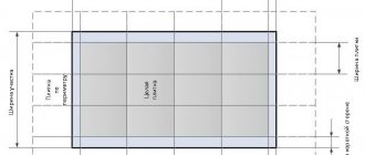
The number of rods used directly depends on the size of the slab, primarily on its thickness (if it is more than 25 cm, two-layer reinforcement will be required). We use as an example a house whose base measures 8x4 meters. The minimum grid pitch, according to SNiP, should be 20 centimeters. Accordingly, the number of rods in length will be equal to:
Let's multiply the resulting quantity by 5% to ensure a reserve. The linear footage of the reinforcement will be:
As we mentioned earlier, the diameter of the rod should be selected in accordance with the loads on the slab. The minimum degree of reinforcement for concrete M-200 and M-300, respectively, is 0.1 and 0.15%, which should also be included in the calculation of material consumption. Knowing these parameters, you can accurately calculate the material consumption for a foundation slab with reinforcement.
For example, let’s take a slab measuring 6x6 m and 20 cm thick and calculate the parameters of the reinforcement belt located directly in the interface zone with an area of 1.2 m2. The optimal value of the reinforcement area is 0.3% of the slab area, respectively:
For one layer of reinforcing belt, in which the elements are located in increments of 10 cm, the area of the reinforcement used must be no less than:
Several types of reinforcing bars are suitable for reinforcing the foundation slab. All available options indicating the length and cross-sectional area are available for review in GOST 5781-82. From the results of our example, it follows that the most suitable rod is 14 mm in diameter (a total of 12 rods will be used for each interface zone). With a slab side of 600 cm, the optimal pitch of the frame grid will be 30 cm (for the horizontal direction), the same step will be used for the vertical direction, but 8 mm rods will be used.
To present the calculations in a more visual form, it is necessary to create a drawing of a metal frame. It will help in calculating the total number of rods that will be used during the installation process. For our example, the total consumption of reinforcement will be 515.2 linear meters of 12 mm reinforcing bars and 56 meters of 8 mm bars.
Assembly of load structures, their calculation
| No. | Type of structures | Formulas for accurate calculations | Load data kg/m² | ||
| 2nd floor. Missing data | – | – | – | ||
| 1. | Stove (160) | g = 0.16m * 2.7 m/m '2 = 0.432 m/m '2 | 432 | 1.1 | 475 |
| 2. | C.-p. screeds are equal (30) | g = 0.03*1.8 m/m '2 = 0.054 m/m '2 | 54 | 1.1 | 60 |
| 3. | Ceramic tiles | Missing data | 27 | 1.1 | 30 |
| 4. | Weight indicators | Snip = 2.01 0.7 – 85* | 50 | 1,3 | 65 |
| 5. | Loads, useful type | Snip = 2.01 0.7 – 85* | 150 | 1,3 | 200 |
| 6. | Data output No data | – | – | 830 | |
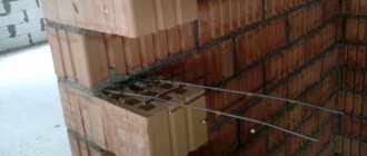
Tying the reinforcement cage
If, before construction work, calculations were made of the maximum load created by the building structure on the foundation, the connection method is included directly in the working drawing. But in practice, the bonding or welding method is used to combine the elements of a metal frame. At the same time, builders are gradually abandoning welding, since heating the metal causes its deformation and changes in structure. The bonding method avoids these disadvantages, providing the lattice with additional flexibility.
Steel wire with a diameter of 4 mm is best suited for tying rods. Possessing the necessary strength, it remains flexible and is quite easy to work with using ordinary pliers.
A few tips for proper tying of reinforcement:
- When connecting rods along their length, an overlap of about 250 mm or more is left;
- Using rods of different diameters, the thinner ones should be placed on top;
- Knitting is preferable to welding; only in exceptional situations should one switch to the welding method;
- In areas of increased deflection, the structure is reinforced with additional rods.
An example of a diagram (drawing) of reinforcement for a slab foundation.
The procedure for constructing a frame for reinforcing foundation slabs:
- Creation of formwork along the outer perimeter, installation of rolled waterproofing material;
- Installation of a horizontal reinforcement belt at a height of 50 mm from the underlying sand and gravel cushion. It is necessary to ensure that the rods do not touch the walls of the formwork and the cushion;
- Installation of vertical rods in increments of 20-40 cm. They are connected to the elements of the horizontal belt in the lower base. In the corners, vertical rods can be installed in smaller increments, strengthening them with longitudinal rods to increase the strength of the structure;
- For horizontal belt elements, it is better to choose an interval of 15 cm or less (depending on the thickness of the slab);
- The top edge of the vertical chord must be above the slab in order to combine the reinforcing layer of the foundation slab with the wall structure.
Next, the entire structure will be filled with concrete.
Description of reinforcement schemes
Reinforcement along the width of the slab
Most often, reinforcement of a slab foundation is carried out along the main width of the slab using a mesh with the same cell size. When calculating the grid spacing, the size of the foundation and the amount of load it will take upon itself after the building is erected are taken into account. It is possible to use rods of different diameters, with thicker rods placed under the bottom of the structure. It is recommended to use reinforcement along the main width for the lower part of the slab to distribute the load over the entire area.
U-shaped rods are placed in the end parts, connecting the lower and upper reinforcing balls into a single whole. These elements further strengthen the structure, compensating for the destructive effects of torques.
Creating a floor using corrugated sheets
An interesting technology that allows you to create floors with high load-bearing capacity. Profiled sheets N-60/N-75 are suitable for work. The sheets are mounted in such a way that after pouring, ribs are formed at the bottom. The reinforcing mesh is installed on top of the sheet at a distance of 150 mm. A rod with a diameter of 12-14 mm is installed in the ribs; plastic clamps should be used to mount the rods.
Solid slab
This technology is used if it is necessary to create a slab foundation or span with a thickness of no more than 200 mm. The frame consists of two grids located in parallel planes. For installation of meshes, rods with a diameter of 10 mm are suitable. In the middle of the structure, additional reinforcing elements with a length of 40 cm or more are installed in the lower grid. The frequency of installation of reinforcing elements should be equal to the pitch of the main grid.
The support points of the slab must be equipped with additional reinforcement, installing it in the upper part of the structure. The ends of the mesh are also fastened with U-shaped elements combining the segments.
Calculation of AKP-SP data
c. With AKP-SP fittings Ø 14, in increments of 200
A2 = 7.69 cm2.
Coefficient data to accurately determine k1pr * k2pr * k3pr data.
M = Fa/b*h0 = Ea/Eb = 7.69cm2/100 cm * 14 cm * 550000 kg/cm2 / 3.1 * 10'2 kg/cm = 0.0098.
K1rp = 0.664, k1 = 0.043, k2 = 0.10.
Axle data curves under simultaneous actions, constant, long-term, short-term loads.
1/p = 1/Ea*Fa*h2 = Mkp/k1kp + M – k2 *b*n2*Rbin / k1 = 1/2*10'2 kg/cm * 2.51 cm2 *13'2 cm2 * 22,000 ru * cm/ 064 + 71000 kg*cm – 0.1*100cm * 16 cm2 * 14.3 kg/cm2 = 1/848380000 * 34 375 + 71000 – 36 608/ 0.43 = 0.000135 1/cm = 13.5*10′-5 1/cm .
The maximum deflection data in the middle of the spans are: f = 1/p *S*l2 = 13.5 * 10′-5 1/cm * 5/48 * 300'2 cm2 = 1.29 cm. f = 1/200 = 300 cm/200 = 1.5 cm. Fm = 1.27 cm = f = 1.5 cm.
The conditions are met, the accepted reinforcement is calculated correctly (Ø14 AKP-SP, taking into account the step equal to 200
d. For valves of AKP-SP class Ø 10, in steps of 100
Longitudinal section of the slab.
A2 = 7.86 cm2.
These coefficients are equal – Kpr * k1 * k2.
M = Fa/b*h0 = Ea/Eb = 7.69cm2/100 cm * 14 cm * 550000 kg/cm2 / 3.1 * 10'2 kg/cm = 0.0098.
K1rp = 0.664, k1 = 0.043, k2 = 0.10.
Data on the curvature of the axis for constant, long-term, short-term loads.
1/p = 1/Ea*Fa*h2 = Mkp/k1kp + M – k2 *b*n2*Rbin / k1 = 1/2*10'2 kg/cm * 2.51 cm2 *13'2 cm2 * 22,000 ru * cm/ 064 + 71000 kg*cm – 0.1*100cm * 16 cm2 * 14.3 kg/cm2 = 1/848380000 * 34 375 + 71000 – 36 608/ 0.43 = 0.000135 1/cm = 13.5*10′-5 1/cm .
The maximum deflection data in the middle of the spans are:
f = 1/p *S*l2 = 13.5 * 10′-5 1/cm * 5/48 * 300'2 cm2 = 1.29 cm. f = 1/200 = 300 cm/200 = 1.5 cm. Fm = 1.27 cm = f = 1.5 cm.
fm = 1.27 cm = f = 1.5 cm – the conditions are met, the accepted reinforcement is calculated correctly (Ø14 AKP-SP, taking into account the step equal to 100).
e. For fittings of class AKP-SPØ 8, taking into account a pitch of 100, calculation
The data is calculated using the formula:
A2 = 5.05 cm2.
Coefficients for exact determinations are k1*k2*k3.
M = Fa/b*h0 = Ea/Eb = 7.69cm2/100 cm * 14 cm * 550000 kg/cm2 / 3.1 * 10'2 kg/cm = 0.0098.
K1rp = 0.664, k1 = 0.043, k2 = 0.10.
The curvature of the axis is affected by the simultaneous actions of constant and long-term (and non-long-term) loads of different nature. Calculate using the formula:
1/p = 1/Ea*Fa*h2 = Mkp/k1kp + M – k2 *b*n2*Rbin / k1 = 1/2*10'2 kg/cm * 2.51 cm2 *13'2 cm2 * 22,000 ru * CM/064 + 71000 KG * CM - 0.1 * 100CM * 16 CM2 * 14.3 KG/CM2 = 1/848380000 * 375 + 71000 - 36 608/0.43 = 0.000135 1/CM = 0.00021 1/CM = 21 * 10 ′ -5 1/cm.
The maximum deflection data in the middle of the spans are:
f = 1/p *S*l2 = 13.5 * 10′-5 1/cm * 5/48 * 300'2 cm2 = 2 cm. f = 1/200 = 300 cm/200 = 1.5 cm. Fm = 2 cm = f = 1.5 cm.
All conditions are met using reinforcement, where (Ø8 AKP-SP, taking into account the pitch equal to 200).
Installation sequence of a monolithic slab
To ensure the safety of a reinforced concrete slab for a long time, it must be placed on a bed of sand-crushed stone mixture and protected with insulation and a waterproofing layer. The general progress of work can be divided into the following stages:
- preliminary cleaning of the construction site from vegetation and foreign objects;
- digging a pit, the parameters of which are calculated according to SNiP, taking into account the mass of the building and the characteristics of the soil;
- the bottom of the pit is equipped with ditches for drainage, the surface of the ditches is covered with geotextile material;
- A 30 cm thick sand layer is poured over the entire area of the pit, and a 20 cm layer of crushed stone is placed on top of it;
- an additional layer of roofing felt is placed on top of the resulting cushion;
- installation of formwork, consisting of boards 2 cm thick, fastened together with nails behind fixed external supports;
- erection of a reinforcing frame, the distance between metal rods and wooden formwork should not be less than 5 cm;
- After pouring the concrete, processing and hardening, the formwork is dismantled and the main construction work begins.
Do-it-yourself pouring and grounding of the slab
After completing the installation of the reinforced frame of the monolithic slab, it is necessary to carry out grounding. This procedure involves installing an outer ring made of galvanized strip. This ring will protrude from the outside of the slab, being its integral part. The grounding is equipped with connecting busbars, to which the rain drain elements and lightning rod will be attached. The busbars can also be taken out at the point where the electrical network is connected to the house to provide grounding for the internal electrical wiring.
The foundation is poured after completion of all work related to the installation of the reinforcing frame. During the process of mixing the solution, fiber can be added to the concrete if the requirements of SNiP require additional reinforcement of the concrete base. The filling process is carried out continuously until the entire volume is filled. Upon completion, the mixture must be freed from air bubbles by vibration compaction. The slab will gain the necessary strength after 4 weeks.
Types of floors
Floors can be made of wood or reinforced concrete, which depends on the operating conditions of the structure and calculations. The most popular is reinforced concrete, which has good strength characteristics, resistance to various loads, affordable cost and ease of creation and installation.
By type of construction there are:
Standard – represented by ready-made reinforced concrete slabs of different configurations (size, shape, thickness)
Monolithic ceiling, the reinforcement of which is carried out directly on site
According to the purpose of the plates there are:
1. Basement – separate the walls of the basement from the lower floors
2. Interfloor – delimit floors
3. Attics - demarcate living spaces and under-roof space
A monolithic floor slab, correctly manufactured in accordance with all standards and parameters, the reinforcement of which is carried out in accordance with the established requirements of SNiP, has the main advantage - weight reduction due to the presence of cavities formed during pouring.
According to the shape and number of voids, the slab can be:
Multi-hollow - with longitudinal round cavities Hollow - shaped narrow panels that are most often used as inserts Ribbed - a complex profile with special characteristics
Ready-made structures are relevant for large-scale construction - usually multi-story high-rise buildings and large structures are built from them. Disadvantages include: the presence of joints, the need to use special lifting equipment, the ability to create only rooms of standard sizes, the inability to design openings for hoods, shaped ceilings and other shapes.
It is also important that the installation of monolithic floor slabs significantly increases the total cost of the work in the estimate. Therefore, in individual construction, floors are usually manufactured on site, pouring reinforced mesh with concrete directly on the site.
Frequent mistakes made during the reinforcement process
In order to provide the slab with the necessary properties and protect it from premature destruction, the technological process of reinforcing a monolithic foundation slab should be strictly followed. Below is a small list of mistakes made by inexperienced builders:
- Do not install plastic film over the poured concrete mixture. Its absence provokes the leakage of cement laitance through the cracks in the formwork. As a result, the frozen solution will become covered with surface cracks.
- After filling the sand-crushed stone cushion, it is not compacted or covered with film. During operation, the foundation will begin to deform and deep cracks will appear.
- When installing the formwork, the cracks through which fresh mortar will begin to flow out are not sealed. This error will lead to the formation of unevenness in the slab.
- The absence of a waterproofing layer between the slab and the ground surface leads to rapid destruction of the foundation, which can only be stopped through expensive work.
- Using stones as foundation spacers.
- During the installation of the reinforcing mesh, the reinforcement bars are fixed in the ground, as a result of which the metal will begin to deteriorate quite quickly under the influence of corrosion.
- When arranging the foundation, a sand-crushed stone cushion is not poured, which reduces the strength characteristics of the slab. Another common mistake is to use only crushed stone for the cushion, while the minimum sand content in the mixture should be 40%.
- The mesh spacing when reinforcing a slab foundation exceeds the maximum limit of 40 cm, or it does not correspond to the calculations for the load on the foundation.
- There is no protective concrete layer at the ends of the reinforcement, which is why it becomes corroded.
- There are no vertical rods under load-bearing walls and columns, as a result the load from the weight of the building is distributed incorrectly.
We have listed only the most serious mistakes that will certainly affect the performance characteristics of the foundation. There are also more unobvious nuances that only experienced builders know about. That is why we recommend entrusting such important work as reinforcing a slab foundation only to craftsmen with a good reputation.