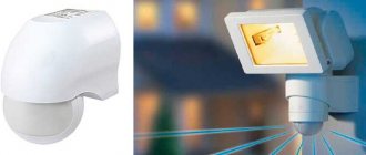
A motion sensor is most often used to turn on lights when you pass or are near them. With its help, you can save electricity and save yourself from having to flip the switch. This device is also used in alarm systems to detect unwanted intrusions. In addition, they can also be found on production lines, where they are needed to automatically perform any technological tasks. Motion sensors are sometimes called presence sensors.
Types of motion sensors
Motion sensors are distinguished by their operating principle; their operation, accuracy and features of use depend on this. Each of them has strengths and weaknesses. The final price of such a sensor also depends on the design and type of element used.
The motion sensor can be made in one housing or in different housings (the control unit is separate from the sensor).
Contact
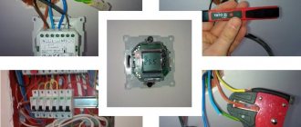
The simplest option for a motion sensor is to use a limit switch or reed switch. A reed switch (sealed contact) is a switch that is activated when a magnetic field appears. The essence of the work is to install a limit switch with normally open contacts or a reed switch on the door, when you open it and enter the room, the contacts will close, turn on the relay, and it will turn on the lighting. Such a diagram is shown below.
Infrared
They are triggered by thermal radiation and react to temperature changes. When you enter the field of view of such a sensor, it is triggered by thermal radiation from your body. The disadvantage of this detection method is false positives. Thermal radiation is inherent in everything that is around. Here are some examples:
1. An IR motion sensor is installed in a room with an electric heater, which periodically turns on and off using a timer or thermostat. When the heater is turned on, false alarms may occur. You can try to avoid this by taking a long time and carefully adjusting the sensitivity, as well as by trying to direct it so that there is no heater in the direct line of sight.
2. When installed outdoors, it may be triggered by gusts of warm wind.
Overall these sensors work fine and are the cheapest option. A PIR sensor is used as a sensitive element; it creates an electric field proportional to thermal radiation.
But the sensor itself does not have a wide directionality; a Fresnel lens is installed on top of it.
It would be more correct to say - a multi-segment lens, or multilens. Pay attention to the window of such a sensor, it is divided into sections; these are lens segments; they focus the incoming radiation into a narrow beam and direct it to the sensitive area of the sensor. As a result, radiation beams from different directions fall on the small receiving window of the pyroelectric sensor.
To increase the efficiency of motion detection, dual or quad sensors or several separate ones can be installed. Thus, the field of view of the device expands.
Based on the above, it should also be noted that the sensor should not be exposed to light from the lamp, and there should be no incandescent lamps in its field of view, this is also a strong source of IR radiation, then the operation of the system as a whole will be unstable and unexpected. IR rays don't travel well through glass, so it won't work if you're walking behind a window or glass door.
This is the most common type of sensor; you can buy it or you can assemble it yourself, so let’s look at its design in detail.
How to assemble an IR motion sensor with your own hands?
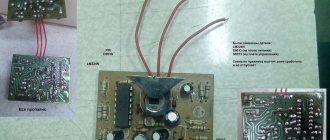
The most common option is the HC-SR501. It can be bought in a radio parts store, on Aliexpress, and is often supplied in Arduino kits. Can be used in conjunction with a microcontroller or independently. It is a printed circuit board with a microcircuit, wiring and one PIR sensor. The latter is covered with a lens, there are two potentiometers on the board, one of them regulates the sensitivity, and the second is the time at which a signal is present at the sensor output. When motion is detected, a signal appears at the output and lasts for the set time.
It is powered by a voltage of 5 to 20 volts, operates at a distance of 3 to 7 meters, and the output signal lasts from 5 to 300 seconds, you can extend this period if you use an NE555 monostable, a microcontroller or a time delay relay. The viewing angle is about 120 degrees.
The photo shows the sensor assembly (left), the lens (bottom right), and the reverse side of the board (top right).
Let's take a closer look at the board. There is a sensitive element on its front side. On the back there is a microcircuit, its wiring, on the right there are two trimming resistors, where the top one is the signal delay time, and the bottom one is the sensitivity. In the lower right part there is a jumper for switching between modes H and L. In mode L, the sensor produces an output signal only for the period of time set by the potentiometer. Mode H produces a signal while you are in the range of the sensor, and when you leave it, the signal will disappear after a time set by the upper potentiometer.
If you want to use a sensor without microcontrollers, then assemble this circuit, all elements are labeled. The circuit is powered through a quenching capacitor, the supply voltage is limited at 12V using a zener diode. When a positive signal appears at the sensor output, relay P is turned on through an NPN transistor (for example BC547, mje13001-9, KT815, KT817 and others). You can use a car relay or any other with a 12V coil.
Self-connection of a motion sensor
Nowadays, a variety of motion sensors (MS) are widely available on the market. Motion sensors are used for various purposes. Often, motion sensors are used to control lighting in rooms where people stay for a short time. These can be stairs, corridors, storage rooms, and other rooms. With the help of DD they control automatic doors, ventilation, air conditioners and other devices. Motion sensors are often elements of alarm systems.
Practice shows that the use of motion sensors to control lighting leads to noticeable energy savings and the cost of installing equipment quickly pays off.
Motion sensors can operate using different physical principles. The industry produces acoustic, ultrasonic, infrared, microwave DD. Some of them are active, some are passive. Active DDs send a signal and then analyze the response. Passive motion sensors receive signals from objects within their coverage area. An example of passive sensors are infrared sensors.
Despite the differences in the principles underlying the operation of different sensors, they are united by a similar operating logic. Typically, when a moving object appears in the sensor’s coverage area, the built-in contact inside the device closes and remains in the on state for some time. The signal generated by the contact can be used to control various actuators.
In addition to the time delay, the most important parameter of the motion sensor is the sensor detection zone. It is characterized by the distance to the moving object and the angle at which the DD “sees” the object. The detection area largely depends on the height and location of the motion sensor. Most DDs are installed on the ceiling or at the top of the walls. This ensures maximum visibility of the sensor. Examples of diagrams of different detection zones are shown in the figure.
Often, to obtain the required detection zone, it is necessary to use more than one motion sensor. For example, on stairs you have to install a motion sensor on each stairwell.
Motion sensor connection diagrams
Motion sensors with one built-in contact usually have three terminals. Two of them serve to power the DD. A phase is supplied to one of the terminals. The phase terminal is marked with the symbol L. The other terminal is supplied with zero (N). The third output is the phase output from the contact. In some cases, the normally open contact has two terminals. Then, to connect the phase to the contact, a jumper is installed between one of the contact terminals and terminal L.
The figure shows the simplest lighting control scheme using a single motion sensor.
The scheme will work as follows. When a person appears in the detection zone, the motion sensor will work, the built-in contact will close and supply a phase to the lamp. The lamp will remain on until movement continues or the time delay expires. After the end of the time delay, the contact will open. In order to avoid making unnecessary movements to light the lamp again, you can install a switch that can be used to bypass (close) the built-in motion sensor contact. Using the switch, you can turn on the light so that it is constantly on. The circuit with the switch is shown in the figure.
Often, motion sensors are used to control lamps in places where there is natural light during daylight hours. In such cases, it is advisable to use a DD with a built-in light sensor, which blocks the operation of the device during the day.
Parallel operation of two motion sensors
It happens that the detection zone of one motion sensor does not cover the entire room where a person may appear. This situation is typical, for example, for a long corridor, when the light should light up regardless of which end of the corridor a person appears. In this case, you can use two motion sensors operating in parallel.
It is easy to see that this circuit, from an electrical point of view, differs little from a circuit with a switch. As in the circuit with a switch, both contacts of the motion sensors are connected in parallel and mutually bypass each other. That is, the lamp will turn on when any of the two sensors is triggered. This scheme is scalable. This means that you can endlessly increase the number of motion sensors working in parallel. An increase in the number of sensors may be required, for example, to illuminate staircases with several flights.
Important! When using such circuits, you must remember that all motion sensors must be powered from the same phase. If this rule is not observed, a short circuit may occur if two sensors are triggered simultaneously.
Sometimes motion sensors have to control loads that are more powerful than one or more light bulbs. Then the limitation on the maximum permissible current of the built-in contact comes into force. The maximum permissible switching current can be found in the product data sheet. Manufacturers often indicate this current on the device body. If the current consumption of the load exceeds the “capabilities” of the motion sensor, then the load is turned on using a magnetic starter, and the starter is controlled using the motion sensor.
The figure shows a diagram for controlling a powerful load using a motion sensor and a magnetic starter.
Can I do it myself?
Despite the low price of sensors, many people try to make the devices themselves and save money. The advantages of such a solution are the ability to thoroughly understand the principle of operation, reduce maintenance costs and “tailor” the device to specific application conditions.
In addition, with proper assembly, you can reduce costs and even upgrade the system.
But there are also disadvantages. Before you start work, you need to purchase equipment, draw a diagram, decide on dimensions and other points. This requires experience and knowledge. However, there is no guarantee that the finished scheme will work.
If you decide to assemble the motion sensor yourself, prepare the following items:
- circuit assembly housing;
- set of elements;
- soldering iron and wires of different sections;
- fastening;
- screwdriver;
- other materials - electrical tape, pliers, cambric.
To turn on the lighting, a sensor with a photocell built into it will be used. A photo relay will act as a switch.
To collect the diagram you will need:
- capacitor (C1);
- operational amplifier DA1;
- phototransistor (VT1);
- resistance R1 to load the collector and create an operating point;
- resistor R2 to implement feedback.
When assembled correctly, the circuit works like this. After light enters VT1, the element is triggered and the phototransistor opens, followed by charging C1. When the voltage is removed from VT1, the capacitor discharges and the voltage decreases.
The light source for the photocell can be a simple laser or an infrared LED.
The assembly proceeds according to the following algorithm:
- Assemble the power supply, adjust it and monitor the current output.
- Connect a resistor to the negative of the power source.
- Connect the diode using the cathode.
- Connect a tuning resistor to the anode.
- Connect the transistor emitter to the negative wire of the power supply.
- Connect the resistor to the base circuit.
After assembly, all that remains is to test the correct operation of the product when light hits it. Possible errors must be eliminated immediately upon detection.
Wiring diagram for a motion sensor for lighting
A motion sensor is an electronic infrared device that detects the presence and movement of a person and helps switch power to lighting and other electrical appliances. It is based on a special detector of temperature changes in space (read about the PIR sensor here). Nowadays there are a lot of models of various Chinese detectors on sale, which are almost all similar to each other and differ only in the design and power of the switched lamps - the connection diagram itself is usually the same.
If you need to connect several powerful lamps at once through this device, then the best solution would be to use a magnetic starter or a powerful relay.
Installation Features
To install it, you need to choose a place that provides the best viewing angles both horizontally and vertically with a maximum coverage area. Most PIR motion sensors have a dead zone, the location of which should be taken into account when choosing their placement height and angle of inclination.
Motion sensor HC-SR501 with regulators
If the sensor is made in a fixed housing and does not have positioning adjustment, then it is necessary to check the technical data sheet for correct placement of the device. Sometimes this device requires the presence of not only phase and neutral wires, but also ground (ground). Although most operate from a regular two-wire 220 V network.
Where can I buy
You can purchase lighting equipment as quickly as possible at your nearest specialty store. The optimal option, in terms of price-quality ratio, remains purchasing from the AliExpress online store. Mandatory long waits for parcels from China are a thing of the past, because now many goods are in intermediate warehouses in destination countries: for example, when ordering, you can select the “Delivery from the Russian Federation” option:
| LED floodlight with motion sensor from 10 to 100 W | LED spotlight COSMOS with DD 20W | Solar panel lamp with DD |
| Motion sensor Aqara Motion Sensor | PIR sensor for lamp | LED floodlight with PIR motion sensor |
Electrical connection diagrams
How to connect a motion sensor with a switch
An option in which it is installed parallel to a conventional switch.
How to connect a motion sensor without a switch
And this is for connecting it directly to a 220 V network without any other buttons.
How to connect several sensors to the network at once
On long stairs or corridors, you may need several pieces that control one lamp or a long white LED strip.
Inside the PIR sensor there is usually a terminal block with standard colored and labeled contacts:
- L , brown or black - phase wire.
- N , blue - neutral wire.
- Ls or L', red - phase return to the lighting lamps.
- ⊥, yellow-green - protective grounding.
Lighting devices should be connected between contacts A and N. Electrical power should be supplied to L and N, strictly observing the polarity of the connection phase. If you are interested in the circuit diagram of the detector, then follow the link at the beginning of the article.
How to install DD to turn on the light: 2 main schemes
It is recommended to install the sensor-lamp system separately from general lighting. In order for the DD to turn on the light to work instead of a switch, a separate line is installed where only the device and the lamp will work. But often it becomes necessary to include a switch in this circuit. This will allow you to turn off the lighting if necessary.
In the photo: a) connecting the sensor without a switch; b) connection with a switch.
Configuring and adjusting the sensor
After installation, it is necessary to carry out the procedure for adjusting the motion sensor for lighting. After all, the geometry of the room is different for everyone (humidity, lighting, wall material).
- LIGHT or LUX - sensitivity threshold for illumination.
- TIME - trigger timer.
- SENSE - sensitivity.
The usual limits for adjusting the timer response time are set in most devices from a few seconds to ten minutes. The photosensitivity threshold can only be set in devices that have an appropriate light sensor. It determines the daylight brightness at which the device stops supplying voltage to the lighting fixtures. Setting the sensor sensitivity is the most subtle and capricious setting. In any case, the sensor should respond to the appearance of a person in the room, and not small animals. When changing the viewing angle of the device, sensitivity adjustment is often required.
Possible problems
Other reasons may also lead to false alarms and incorrect operation of the sensor, which we mentioned above:
- Installing a wall sensor on the ceiling. If such an error was made, the device will not work correctly because the viewing angles are different.
- Random activation of the sensor after it has been turned off. This often happens with IR products when there is a light source next to the device, the beam from which directly hits the sensitive element. Therefore, it is important to place it away from lighting fixtures.
- The influence of drafts, wind and glare. The sensor cannot be mounted on air conditioners, above windows, or in corridors where there is a strong draft. Above places where water accumulates and where direct sunlight falls. Reflected glare hitting the sensitive element of the sensor will lead to its frequent operation.
Necessary information before properly connecting the motion sensor to the light bulb
Modern motion detector models are designed with an infrared or ultrasonic sensor built into it. The plastic design of the device is equipped with a window, which is covered with a special film. This is called a Fresnel lens. When carrying out any work on the sensor, extreme care must be taken not to damage the lens. To make adjustments easier for further adjustments, you can make small marks with a marker.
It must be remembered that all installation work is carried out with the voltage turned off.
Connecting two or more devices to one light bulb plus a diagram
In some situations, when one sensor is not able to cover the entire area of the room, I resort to a method such as connecting two motion sensors to one light bulb. This method is often used by protected objects so that the radius of the sensors and the covered area are as large as possible.
Wall sensors are usually used to minimize dead zones. In other words, the zero phase reaches each sensor without interruption. All sensor inputs are connected in parallel, and the input is connected to the lamp. All motion-sensitive devices are powered from one phase. In the case of installing two devices on one light bulb, you should remember that the power of the light bulb should not be higher than the output power of the devices, this can lead to damage to the devices. The diagram below describes as easily as possible the connection of two motion sensors to a light bulb.
Scheme for connecting two motion sensors to one light bulb
There are situations when a schematic inspection and study of the attached instructions does not bring the desired result. But if you don’t have time to call a specialist, or for some other reason, then you can’t do without a visual aid. Below is a video that shows in the most accessible way how to connect a motion sensor.
You can buy both sensors and light bulbs here: https://avselectro.ru/catalog/4146-lampy-istochniki-sveta - ABC Electric has a large selection and good prices (often there are even sales). In general, we recommend checking it out.
Video on how to connect a motion sensor.
Source: domdvordorogi.ru
How to avoid false positives
To avoid false switching on of lighting in the circuit solutions discussed above, follow these tips:
- Do not place sensors near trees or heating devices.
- Always break only the phase.
- Make sure that light rays, for example from an incandescent lamp, do not penetrate to the sensor.
- Attach the product depending on the type (wall, ceiling).
- Do not install the device near air conditioners or windows where there is air movement.
- Make sure that the glass of the infrared product is clean and undamaged.
Following the above tips allows you to quickly and without errors connect a device to control lighting on the stairs, in an apartment or on the street.
Wiring diagram for a motion sensor for lighting
A motion sensor is an electronic infrared device that detects the presence and movement of a person and helps switch power to lighting and other electrical appliances. It is based on a special detector of temperature changes in space (read about the PIR sensor here). Nowadays there are a lot of models of various Chinese detectors on sale, which are almost all similar to each other and differ only in the design and power of the switched lamps - the connection diagram itself is usually the same.
If you need to connect several powerful lamps at once through this device, then the best solution would be to use a magnetic starter or a powerful relay.
Installation Features
To install it, you need to choose a place that provides the best viewing angles both horizontally and vertically with a maximum coverage area. Most PIR motion sensors have a dead zone, the location of which should be taken into account when choosing their placement height and angle of inclination.
Motion sensor HC-SR501 with regulators
If the sensor is made in a fixed housing and does not have positioning adjustment, then it is necessary to check the technical data sheet for correct placement of the device. Sometimes this device requires the presence of not only phase and neutral wires, but also ground (ground). Although most operate from a regular two-wire 220 V network.
Characteristics
When purchasing a motion sensor, it is important to consider a number of parameters, which determine the features, connection location, and conditions for use.
Main characteristics when choosing:
- WEIGHT. Modern light sensors weigh from 25 to 240 g.
- Maximum load power. When choosing a product, you need to look at the permissible load. Thus, one sensor can switch devices with power from 60 to 2300 W. Please note that when using more powerful devices, it may be necessary to replace the wiring or install a machine with a higher rated current.
- VOLTAGE. The operating voltage varies in a wide range from 1.5 to 220 Volts. Conventionally, motion sensors are divided into several groups - 1.5 V, from 2.2 to 3.6 V, 220 V, 5 or 9 V.
- MAXIMUM VIEWING ANGLE. Here the range is from 30 to 360 degrees. In the latter case, the device operates along the entire perimeter of the room.
- RANGE. The minimum and maximum distance parameters are 8 and 120 m. Here you need to take into account the object on which lighting is provided. You should not choose sensors with an excessively high parameter, because they can react to the movement of strangers.
- RECOMMENDED INSTALLATION HEIGHT. Here the permissible parameter ranges from 1.2 to 16 m.
- PRESENCE OF LED INDICATOR. Some sensors are equipped with an LED that starts blinking when a signal is present. Other LED display options are also possible.
These are the main characteristics that you need to consider when purchasing. We will discuss the selection criteria in more detail below.
Electrical connection diagrams
How to connect a motion sensor with a switch
An option in which it is installed parallel to a conventional switch.
How to connect a motion sensor without a switch
And this is for connecting it directly to a 220 V network without any other buttons.
How to connect several sensors to the network at once
On long stairs or corridors, you may need several pieces that control one lamp or a long white LED strip.
Inside the PIR sensor there is usually a terminal block with standard colored and labeled contacts:
- L , brown or black - phase wire.
- N , blue - neutral wire.
- Ls or L', red - phase return to the lighting lamps.
- ⊥, yellow-green - protective grounding.
Lighting devices should be connected between contacts A and N. Electrical power should be supplied to L and N, strictly observing the polarity of the connection phase. If you are interested in the circuit diagram of the detector, then follow the link at the beginning of the article.
Troubleshooting Possible Errors
One of the common mistakes during installation is poor contact of the neutral wire. This can happen when debris gets into the motion sensor terminal or a loose clamp, causing carbon deposits or oxidation. If the detector does not work, then inspect all the wires, strip them and tighten the clamps properly.
Another reason for the malfunction is deformation or breakage of the aluminum core. Connect a voltmeter to the device. Be careful as the device may not operate even if voltage is present. If this happens, replace the light bulb with a new one, as the problem may be due to a burnt-out filament.
Another malfunction in the operation of the motion sensor is due to the fact that the lighting device does not turn off, despite the correct operation of the detector. Check what time was set in the settings. Perhaps it is too large and the output contact takes a long time to open. Reduce the parameter using the appropriate toggle switch.
Only with the correct connection and technically correct configuration of the motion sensor can you achieve maximum energy savings, comfort and ease of use of the automatic lighting system. At home, it is recommended to use passive detectors, which are less expensive.
Configuring and adjusting the sensor
After installation, it is necessary to carry out the procedure for adjusting the motion sensor for lighting. After all, the geometry of the room is different for everyone (humidity, lighting, wall material).
- LIGHT or LUX - sensitivity threshold for illumination.
- TIME - trigger timer.
- SENSE - sensitivity.
The usual limits for adjusting the timer response time are set in most devices from a few seconds to ten minutes. The photosensitivity threshold can only be set in devices that have an appropriate light sensor. It determines the daylight brightness at which the device stops supplying voltage to the lighting fixtures. Setting the sensor sensitivity is the most subtle and capricious setting. In any case, the sensor should respond to the appearance of a person in the room, and not small animals. When changing the viewing angle of the device, sensitivity adjustment is often required.
Recommendations for choosing an installation location
Sensors can be installed inside the house or outside.
Street sensors monitor the area adjacent to a particular building. The perception range of these devices is usually large. For some devices it reaches hundreds of meters. But such indicators are not particularly suitable for the courtyard of a private house.
When returning home or going out in the dark, the devices will be especially convenient for the owners. The LUX button helps with settings.
Internal sensors work indoors. Differences from other types lie in the following properties:
- Poor protection from atmospheric influences.
- Smaller field of view. If there is no movement, work stops.
- Reduced cost.