Warm floor
The main function of such underfloor heating is to heat the floor and/or room itself.
There are two types of such heaters: water and electric. The first involves laying pipes into the base of the floor, through which warm water is released. This is a cheaper and not entirely safe option, since if the pipes are damaged, not only will you have to remove the entire coating in order to repair the leak, but there is also a very real risk of ruining the repair completely. Read also: about the features of operating an electric heated floor.
As for the electric variation, everything is much more favorable here, although the cost of such a heating project will be more expensive. However, the costs will quickly pay off, because such a system:
- safe;
- very convenient;
- economical;
- In the event of a breakdown, repairs are much easier.
Some people fear that electric heating options use a lot of electricity, but this is not the case. After all, it is worth considering that the main expense is only for warming up. Further, electricity is required only to maintain the set temperature. And a high-quality and competently installed and configured heater will not be a very greedy consumer.
A mixed type of heating will allow you to further reduce electricity consumption, that is, when there is both a heated floor and main heating in the room. Although without the latter, energy consumption will not become a big problem.
In this video you will learn how to connect a cable heated floor to a thermostat:
Features of the device and installation
Despite the apparent complexity of installing heated floors, in reality it is extremely simple, as is the installation itself. The basis of its operation is the conversion of electricity into heat through a conductor having high resistance. This can be a cable or mat that connects to a 220 volt network. The thermostat monitors the degree of heating and temperature.
The thermostat will help maintain the required temperature without overheating the floor
The selected conductor is laid on foil, which is covered with a rough screed 1 cm thick. Under it, in turn, there is a heat insulator, which can be placed directly on the ceiling. The wire itself is secured using a special mounting tape and connected to the thermostat. A temperature sensor is also attached to it, which will record the degree of heating.
After laying and securing, you can apply a basic screed with a thickness of 2 to 5 cm, on which the finishing coating will subsequently be laid
When choosing it, you should pay attention to the admissibility of use with the “warm floor” system.
Thus, the floor heating device includes:
- heater;
- thermostat;
- temperature sensor.
All installation and adjustment work can be carried out even by a person who does not have special knowledge in this area.
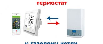
How to connect a thermostat to an infrared heater
Using a thermostat is very convenient; you just need to determine how to properly connect the thermostat to an infrared heater in order to get the maximum effect from using this device.
Necessary materials
Preparing to install the thermostat will not take much time, nor will the installation itself. Even if you have no experience connecting thermostats, you can easily do all the work yourself.
But if you do not have experience working with electrical equipment and even installing a socket is difficult, and you are not familiar with the operating principle of an indicator screwdriver, you should not try to figure out how to connect a mechanical or electronic thermostat. In such cases, it is safer to entrust this work to a professional.
For those who are well versed in electricity and know for sure that before work they should turn off the power to devices and equipment, it is necessary to prepare the following set of tools:
- Drill or screwdriver. They are only needed to drill a hole in the wall to mount the thermostat.
- Pliers for working with electrical cables.
- Indicator screwdriver or tester.
- Pencil, tape measure. They will help determine and mark the place where the temperature regulator will be located.
Also for work you will need an electrical cable that will connect the thermostat and the infrared heating device, a collapsible socket and hardware for attaching the regulator and fixing the cable. When the materials and tools are prepared, you can begin marking and installation.
Connection diagram
The connection diagram of the thermostat to the infrared household heater is selected depending on the device used, the experience and knowledge of the electrical installation specialist.
Standard
In the standard scheme, the thermostat is installed in a ready-made network between the heater itself and the circuit breaker on the panel. The starting point of the network will be the machine. Two wires come from it - phase and zero, which are connected to the corresponding contacts of the thermostat. There are also two wires coming from the thermostat, which are connected to the heating device.
This scheme is also convenient if two or three heaters need to be connected to one thermostat. Located in different rooms, they ensure the same temperature throughout the apartment. For their effective operation, the connection is made as follows:
- Two wires lead from the machine to the thermostat: phase and zero.
- Two wires come from the machine for each heating device.
- Infrared heaters do not connect to each other.
Parallel connection will allow you to safely control several devices at once, without purchasing additional controllers for each of them.
Using a magnetic starter
This scheme is a little more complicated and will take a little longer. But thanks to the use of additional equipment in the form of a magnetic starter, it is possible to connect several heaters to one thermostat at once, including equipment with higher power and industrial systems.
Devices are connected in the following sequence:
- A thermostat is connected to the machine using a cable (phase and neutral).
- The thermostat is connected to the magnetic starter through the output terminals.
- The magnetic starter is connected to heating devices.
In this case, the circuit for connecting the magnetic starter is calculated individually. This will ensure the devices operate safely and efficiently.
Types of thermostats
Based on the type of functions, they can be divided into several groups:
– with one function (temperature maintenance);
Thermostat with one function
– with a large number of functions (programmable).
Programmable temperature controller
Based on their design, thermostats are divided into types: wireless and with wires for communication with the boiler. Install the thermostats in a convenient place, connect the temperature sensor, connect it to the boiler control system and use it.
Room thermostats need a constant flow of air to function properly and properly, so they should not be covered with curtains or blocked by furniture. Devices adjacent to the electric thermostat may interfere with the correct operation of the device: lamps, televisions, heating devices located nearby.
Installation Tips
An incorrectly chosen location for the thermostat is one of the main reasons why there is no effect from using this device. Having studied the diagram of how to connect the thermostat to the heater, some experts take the advice literally and mount the thermostat on ready-made networks, somewhere in the area between the machine and the heating device. As a result, the device reads information about the temperature in the corridor or adjacent room and, based on this data, regulates the operation of the infrared heater.
Connecting a thermostat to a heated floor system
Depending on the type of heating cable in the underfloor heating system, the connection diagram will be different. There are two types of flooring: with a single-core and two-core bundle, the principle of operation between them is similar, but a multi-core cable has a service life, as well as technical indicators for speed and heating height, much higher.
It is easier to connect a thermostat to a single-core system - just connect two neutral cables to one terminal, and the phase to the corresponding socket. In this case, the current will pass through the entire length sequentially along the ring of the bundle.
In a two-core cable, all wires come out from one side, so the connection is made in series - one wire to one terminal. The current in this scheme passes along the entire length of the heating element and returns along the same path in one direction.
Thus, if you follow all the rules and the algorithm for connecting the thermostat to any circuit, all that remains is to adjust the device to the desired parameters by rotating the wheel on the temperature scale.
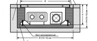
Heating element device.
The heating element is an electric heating element made of a thin-walled metal tube (sheath), the material for which is copper, brass, stainless and carbon steel. Inside the tube there is a spiral of nichrome wire, which has a high electrical resistivity. The ends of the spiral are connected to metal leads with which the heater is connected to the supply voltage.
The spiral is insulated from the walls of the tube by a compressed electrically insulating filler, which serves to remove thermal energy from the spiral and securely fixes it in the center of the tube along its entire length. Fused magnesium oxide, corundum or quartz sand is used as filler. To protect the filler from the penetration of moisture from the environment, the ends of the heating element are sealed with thermal and moisture-resistant varnish.
The heater leads are insulated from the walls of the tube and rigidly fixed with ceramic insulators. The supply wires are connected to the threaded ends of the terminals using nuts and washers.
The heating element works as follows: when an electric current passes through a spiral, it heats up and heats the filler and the walls of the tube, through which heat is radiated into the environment.
fins are used to increase heat transfer from heating elements.
, made of material with good thermal conductivity. As a rule, corrugated steel tape is used for fins, wound in a spiral on the outer shell of the heating element.
The use of such a design solution helps to reduce the overall dimensions and current load of the heater.
Thermostatic control valves
The thermostatic valve is a simple solution to the problem of obtaining a coolant at a given temperature by mixing colder water with warmer water. The three-way valve is shown below:
Three-way valve
Scheme for connecting a three-way valve to the heating system:
Scheme for connecting a three-way valve to a heating system
Piping diagram for a solid fuel boiler using a thermostatic three-way valve:
Piping diagram for a solid fuel boiler using a thermostatic three-way valve
Piping diagram for a gas boiler using a thermostatic three-way valve:
Piping diagram for a gas boiler using a thermostatic three-way valve
The thermostatic radiator valve allows you to control the temperature in the room by varying the flow of hot water through the radiator. They regulate the flow of hot water through the radiator, but do not control the boiler. Such devices must be installed to adjust the temperature needed in each individual room.
This idea should be considered as an addition to the thermal control installation. Also, such devices require periodic readjustment and regular performance checks (every six months when changing operating modes).
Prices for thermostats of different models
The cost of thermostats for heating boilers depends on the type of device, the number of supported functions and the manufacturer. The most advanced models of programmable thermostats with a large selection of settings will cost much more than models of simple mechanical devices, however, their level of accuracy is much higher.
When choosing one or another type of device, it is worth considering the level of energy saving that it can provide to the heating device and the degree of ease of control of the equipment to achieve a comfortable indoor climate. The approximate price of a mechanical thermostat for a Baxi heating boiler with a temperature setting range from 5 to 30°C and frost protection is 1,180 rubles.
It is recommended to choose a thermostat and boiler from the same manufacturer, this will ensure uninterrupted operation of the entire system.
You can buy a room thermostat for a mechanical gas boiler, model SAS816WHB-0, with a 5-minute response delay option for RUB 1,490. A special feature of this device is the ability to control not only the operation of gas heating equipment, but also the operation of the air conditioner. A room mechanical thermostat Cewal RQ10 will cost you 790 rubles.
The estimated cost of an electronic wireless thermostat for the Salus Controls 091 FLRF boiler is RUB 5,200. The functions of the device include two heating modes (economical and comfortable), setting weekly programs, three levels of temperature control, 9 heating system control programs. You can buy a thermostat for the solid fuel boiler AURATON S14, which is a multifunctional device, at a price of 6,700 rubles.
By purchasing a thermostat for a heating boiler, you can not only set a comfortable temperature for each room during the cold season, but also extend the life of your heating equipment.
Preparatory work
Before you begin connecting the regulator, it is necessary to carry out a number of preparatory steps. First, determine where it will be located, taking into account a number of nuances:
- The device should not be installed where it may be exposed to direct sunlight; installation in drafts is not recommended. This is especially true for models with a built-in sensor, which will regulate the temperature according to the air flow of the room.
- It is also undesirable to install the regulator on external walls in contact with the street, as this may lead to incorrect readings.
- The installation height of the device is an equally important point. Installation at a height of at least 400 mm is prescribed.
- It is prohibited to install temperature control devices in rooms with high humidity, since almost no model is equipped with a moisture-proof housing. Therefore, if the heated floor is located in a bathroom, shower or bathhouse, then the regulator itself must be moved to the next room, where it will not be exposed to excess moisture.
- The temperature sensor must be located no closer than 500 mm from the wall, in the case of a cable floor model - between the turns in the center. If the film version is used, then the thermometer head is located in the center of the carbon heating strip.
For more convenient and comfortable installation, it is recommended to use an extended 60 mm socket box. This will allow you to freely position all the wires connected to the device.
For heated floors, it is recommended to install a separate dedicated power line with a copper cable with a wire cross-section of 2.5 mm, which can easily withstand a load of up to 3.5 kilowatts. Moreover, the line must be equipped with a separate 16 ampere circuit breaker.
Before you start connecting, you need to make a groove from the installation site of the device to the floor. It should fit two corrugated pipes with a diameter of 10 mm. In one of them there will be wires to the “cold ends”, in the other - the temperature sensor line. It is especially useful to place the sensor in a corrugated tube, since they can often fail, and in order not to open the coating every time, it will be enough to simply pull out the old one and just as easily insert a new one.
If the screed is designed to be quite thick (35–50 mm), then the corrugated tubes do not need to be immersed in the groove on the floor. Otherwise, you will have to prepare a corresponding groove here too. The ends of the corrugation should be plugged so that the solution does not get there during the process.
When connecting a thermostat to a film-type heated floor, corrugated tubes are not used, since here the principle of measuring temperature will be different.
Examination
Despite their simplicity and reliability, capillary thermostats fail. This is due to the following factors:
- Carbon deposits on electrical contacts. Fixing this malfunction is very simple if the mechanism is suitable for disassembly. Carbon deposits are removed by cleaning the contact group with fine sandpaper. As a result of sticking, dents may form on the surface of the contacts. Cleaning is carried out until the surface is completely leveled.
- Loss of membrane elasticity. For collapsible devices, this problem is solved by leveling the surface. For those that cannot be repaired, the defect cannot be eliminated.
- Breakdown of the tube or flask of the capillary system. The only solution is to completely replace the device. In some workshops, the flask is filled with liquid and sealed. But the cost of repair is often higher than the new original.
To determine the operability of an element, you can only check the contact group. Often, regulators for household use are equipped with 3–4 contacts, 2 of which are in the closed (working position), and the next 2 contacts close when the mechanism is activated. To check you need:
- Set the tester to dialing mode with sound notification.
- Connect one probe to the first contact of the element.
- The second one is to find the contact with which the first one is closed. The tester's audio alert will indicate it.
- Next, the flask must be brought to a heating device or open flame without disconnecting the tester probes.
- When the response temperature is reached, the membrane will open the contacts, thereby interrupting the tester's notification.
- Now you need to ring contact 3 of the mechanism. To do this, attach one probe to a contact that has not been tested, and with the second probe find a circuit from the tested terminals. An audible alert will indicate that the circuit is closed and the correct terminal has been found.
Successful testing of all terminals is a sign of complete serviceability of the regulator.
A full check can be carried out in the same way, only with an increase in the trigger moment.
Central thermostat
This thermostat is located far away from your boiler and usually allows you to turn the heating on or off throughout the house. Older versions are connected by wires to the boiler; newer systems tend to send signals to the device's command post. It is the new type of devices that are equipped with quite expensive but effective appliances: double-circuit boilers Ferroli, Beretta and domestic AOGV.
The most famous are room thermostats for double-circuit boilers of the Gsm and Protherm brands. They have a built-in dilatometric thermostat for the boiler, which, depending on the model, can operate remotely; this technology is often used for an electric boiler or solid fuel units.
The room thermostat turns off the heating of the system as needed. It works by measuring the air temperature, turning on the heating when the air temperature drops below the thermostat setting, and turning it off when the set temperature is reached.
Adviсe:
- It is recommended to set the thermostat to 20°C;
- At night, the set temperature should be between 19-21° C.
- It is advisable that the temperature in the children's room is about 22 ° C.
- The temperature should not fall below 22°C in rooms for elderly and disabled people.
As a rule, the temperature of the entire house or individual rooms is based on only one climate microcontroller in the heating system. The best option is to place it in the living room or bedroom, which should probably be the most visited place in the house.
Room thermostats need free air flow to measure temperature, so they should not be covered with curtains or blocked by furniture. Devices adjacent to the electric thermostat may interfere with the correct operation of the device. These include lamps, TVs, neighbors' boilers through the wall, touch switches.
What is a thermostat
A thermostat or thermostat combines two devices.
The first one measures the indoor temperature at certain intervals and records this data. The second device regulates the operation of the heater.
Internal electronics or mechanisms (depending on the design and features of a particular model) coordinate the operation of the two units. The thermostat takes temperature measurements and if they are higher than the set mode, a signal is sent to the heater to stop working. Next, the temperature is measured in the same mode and as soon as it drops below the desired temperature, the heater turns on again.
Thus, connecting an infrared household heater through a thermostat allows you to constantly maintain the desired temperature in the room.
Types and characteristics of thermostats
Thermostats are presented in a wide range of models; they can have different designs and vary greatly in size. Their main difference is in the principle of operation; they can be electrical or mechanical.
- Mechanical. They have poor functionality and only allow you to set the temperature that should be maintained indoors. The front panel of the thermostat can also have an operation indicator and a power button. This device measures temperature rather approximately, but this is quite enough to create comfort in living spaces.
- Electronic. They are equipped with a display on which you can set fairly accurate temperature readings, set a schedule for changing the temperature at night, and adjust the operation of the heating system for a week or even a month. Some models are controlled remotely, including using mobile phones.
Areas of application of thermostats
Thermostats are widely used in various fields, both in industry and in everyday life. Most often, these devices can be found in underfloor heating systems with a heating element in the form of a heating cable, which is located in the screed. When power is supplied to the electrodes, the wires heat up and give off heat to all surrounding layers; for proper operation, the system is equipped with a temperature sensor built into the screed. The controller can be used for electric or water heated floors, the principle of its operation does not change.
Thermostat with sensor for heated floors
The thermostat is also used in heating or heating boilers to automatically adjust the heating level of the internal environment. Many manufacturers equip heating devices with these devices already at the manufacturing stage, but even if the boiler design does not provide for this, you can install the controller on the line yourself.
Where to buy thermostats for heating boilers
You can buy thermostats for gas boilers, electric and solid fuel heating equipment at specialized points selling heating equipment, as well as on websites and online stores selling elements of heating systems. The catalogs present a huge selection of modern thermostats of various types from leading manufacturers. All devices are accompanied by a manufacturer's warranty.
The modern market offers a huge selection of thermostats, both simple and the latest models.
The product range includes wired and wireless models, mechanical and electronic thermostats for solid fuel boilers, gas, electric and diesel installations, as well as convectors, infrared heaters and underfloor heating systems. All products from the catalog have quality certificates.
You can place an order and buy a thermostat for heating using a convenient search system on the Internet resource. Here you can not only preview the functions and appearance of the devices, but also consult with experts about the compatibility of the devices with a specific type of heating equipment. Experienced managers are ready to share any necessary information regarding thermostats and their functionality.
By purchasing a thermostat through an online store, you will receive a high-quality device and qualified advice from specialists.
Another advantage of online purchasing is that it is possible to get acquainted with the cost of devices in different companies and make a comparative review of prices. Having chosen a thermostat, you can get competent advice on its installation, connection and configuration. Some companies offer device installation and setup services. All questions you are interested in can be clarified by phone numbers located in the contact section.
Programmable room thermostat
A programmable electronic room thermostat allows you to select the desired and comfortable temperature at any time; it is easy to reconfigure and change the operating mode. The timer allows you to set a different heating pattern on weekdays and weekends. Some timers allow you to set different settings for each day of the week, which can be useful for people who work part-time or shift work. Many Terneo and KChM models are equipped with such thermostats.
Programmable room thermostat
A programmable room thermostat allows you to set individual heating standards for each day in accordance with your lifestyle and maintain the temperature of the house all the time, regardless of the presence or departure of the owners. Video: Connecting a room thermostat to a gas boiler
If the heating system is controlled by a boiler with a radiator, as a rule, only one programmable room thermostat is needed to control the entire house. Some patterns need to be adjusted in the spring and fall as the clocks move forward and backward or certain changes in climatic conditions occur. We also recommend changing the temperature settings when changing from day to night.
This climate controller has several options that expand its capabilities:
- “Party”, which stops heating for several hours, then resumes;
- “Override” allows you to temporarily change the programmed temperatures during one of the configured periods;
- “Holiday” increases the heating intensity or reduces it for a certain number of days.
Setting up a thermostat (temperature controller) for a heating boiler
After you buy a thermostat for your heating boiler and connect it to your heating equipment, you will need to configure it. Each product comes with instructions that outline how to set it up. Having carefully studied it, you can independently set the necessary mode that meets the individual level of comfort of the microclimate.
On the external panel of the device there are buttons and switches through which settings are carried out. The switches allow you to control heating and air conditioning, delay switching on (does not allow the boiler to start operating during a short-term drop in temperature, for example, a draft) and temperature deviation (if you set the fluctuation value to 1°C, switching on or off will be available when the temperature increases or decreases by 0.5 degrees).
To correctly configure the operation of the thermostat for a heating boiler, it is better to contact specialists.
Using the buttons, two modes are set: optimal and economical. Thus, during the day the temperature will be provided at an optimal value, at night the temperature will drop to a level sufficient for a pleasant sleep. This mode will allow you to significantly save on energy resources. Various models of thermostats have several set modes, one of which can be selected for use.
On a note! In rooms where children and the elderly are most often present, it is recommended not to lower the temperature below 22°C.
Connecting the thermostat
Since thermostats can be used both to control heating elements and control the cooler, the device has two types of contacts and terminals. When connecting the device to the system yourself, you must strictly observe the polarity of the contacts and avoid contradictions in the circuit.
Thermostat connection diagram
No electrical connection is required to connect a mechanical thermostat, since all control and opening of the switch is accomplished by physically changing the characteristics of the heating plate. To connect this device you need to follow the algorithm below:
- In the documentation for the devices there is a designation of the terminals by numbers; in accordance with these indicators, it is necessary to assemble the system. First of all, you need to connect the neutral cable to the electrodes of the box and take it directly to the consumed heating elements, for example, a heated floor;
- The phase is supplied to the controller directly, without connecting to household appliances. The box itself will distribute electricity when the contacts are turned on. In some devices, it is necessary to lay a jumper inside the thermostat from the positive wire to the operation indicator, which shows a signal at the moment the heater is turned on and throughout the entire period of operation;
- The control device contains terminals for connecting a cooling heating element, as well as for an external temperature sensor. All devices must be connected in series, and the current must be turned off completely. This is a typical connection diagram for a thermostat, which is most common in underfloor heating or infrared heating systems;
- The temperature sensor is connected last, after which a test run of the system is performed and the voltage on all elements is checked.
Scheme using a machine
There is also a diagram for connecting a thermostat using a magnetic circuit breaker; most often, this scheme is used when there are several controlled devices that require high voltage current for operation. In this case, the machine is connected to an open network of the positive cable in parallel with the thermostat; in addition, there is a connecting cable with the control device. Current is supplied to consuming devices through a circuit breaker, but it is controlled by a thermostat. The heating elements are connected to the controller only on a parallel line and through an automatic machine, this allows the system to operate with high voltage without interruption and in a safe mode. In the event of an emergency, the switch will operate and completely de-energize all devices.
Thus, it is clear from the diagram that the thermostat is connected to heating or cooling devices immediately before voltage is applied to them, that is, the controller will be the first element in the system. Many thermostats are equipped with an electronic chip and processor, which, in addition to temperature indicators, provide additional data on various indicators, such as the state of humidity in the room, pressure and the time required to achieve the set parameters. Such devices have a much higher cost than mechanical thermostats for household use.
Purpose of magnetic starting devices
Installation tips and tricks Before assembling the circuit, you need to free the working area from the current and check that there is no voltage with a tester.
In case of blocking of the contactor, the fourth pair is taken, which works with 3 power pairs. Compressors, pumps and air conditioners, heating furnaces, conveyor belts, lighting circuits are where and not only you can find MP and KM in their control systems. Installation tips and tricks Before assembling the circuit, you need to free the working area from the current and check that there is no voltage with a tester.
Set the core voltage designation which is mentioned on it and not on the starter. It consists of two buttons: normally open for turning on; normally closed to turn off. It's the easiest thing to deal with.
The starter starts turning on with the closing of the normally open contacts and the opening of the normally closed ones. This is an important aspect, because if connected incorrectly, the core may burn out or will not fully start the necessary contactors.
A good example. Our readers recommend! The fixed part is the lower one and is fixed to the body, the upper one is spring-loaded and can move freely.
In this case, even with a certain complexity of the circuit, connecting it will not be difficult at all. Preparation for assembly Before directly assembling the circuit for connection, you need to: Free the working area from current and check that there is no voltage with a tester. It includes two pairs of contact groups consisting of normally closed and normally open contacts.
How does it work
The magnetic starter can be turned off via the STOP button, while the voltage is removed from the control coil and the springs return the contacts to their original position. Magnetic starters are designed for small currents - up to 10 amperes, which are used when operating all types of electrical equipment.
Types of thermostats
The floor temperature controller can be of three types:
Electro-mechanical thermostats. In appearance and principle of operation, they resemble a similar device on an iron: there is a switch, by turning which you set the required temperature. These are the cheapest and easiest to operate devices.
Electromechanical thermostat for electrically heated floors
Digital. More expensive models. They are controlled not using a graduated wheel, but using buttons (tactile or touch - depending on the model). They usually also have a digital panel that displays the current temperature and/or the set value.
Digital regulators - have a slightly more “advanced” look
Varieties
There are 2 main types of temperature controller. Mechanical devices have manual adjustment of the response temperature. They are among the simplest devices.
There are electronic regulators. They can be adjusted remotely via a computer or Wi-Fi network.
Non-adjustable sensors are increasingly appearing on the market. Such options cannot be configured at the moment of operation; they have a very narrow scope of application.
Types of thermostats
There are two main types of thermostats, which differ depending on the principle of operation:
- Mechanical devices are thermostats that regulate the temperature of the actuator by opening the contact between two plates of different densities. When the sensor heats up, the signal enters the contactor body and transmits a pulse to open or close the plates;
Electronic thermostat
- Electronic thermostat. In this case, the information coming from the temperature sensor is analyzed in a digital processor, only after which the command to supply power to the heating element is executed.
In both cases, control is carried out manually, by setting the required temperature on the controller body. You can also classify thermostats based on visualization and control keys. Thermostats come with rotating dials, adjustment buttons or a touch screen. The operating principle of all of the listed products does not differ significantly from each other.
There is also a classification of thermostats by type of placement: external or internal. Depending on the task being solved, the device can be installed in a wall in a pre-made niche. The construction size of such a device coincides with an ordinary socket, so it is often mounted in a hole cut with a crown.
An externally located thermostat has a thicker body, which is covered on all sides with plastic plates. The downside of such a device is its size; due to the impossibility of placing the device inside the wall, it will protrude on the plane; in addition, when connecting a cable to it, you will have to create an additional channel from a corrugated pipe or pencil case.
Remote thermostats and choosing a location for their installation
A significant advantage in favor of electronic models can be the presence of remote thermostats. In this case, adjustment occurs using a separate panel, which can be placed in any place convenient for you. The choice of location for a remote thermostat in any building should be guided by safety and comfort parameters. It is better to place the thermostat out of the reach of children; it is also worth considering factors that can damage the device.
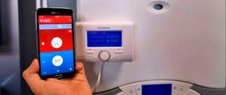
Currently, electronic thermostats with a Wi-FI module are also produced. Data from thermostats can be transferred directly to your smartphone using special applications created by developers. Using such applications, you can adjust the temperature remotely. Such models will fit perfectly into the “smart home” system.
Connection recommendations
To increase the service life of the electronic temperature sensor, it is not recommended to install it in drafty areas or in places where there is active exposure to direct sunlight. Thanks to a simple thermostat connection diagram, almost any home DIYer can handle this job. However, first you need to decide on the connection method:
- Classical.
- Using a magnetic starter.
Both options are worth considering in detail.
Standard scheme
One of the important parameters of any thermostat is the power indicator. One device can be used to control several room heating devices. The number of heating devices that can be connected to it depends on the power of the thermostat. At home, it is quite enough to use devices with a power of no more than 3 kW.
Most often, thermostats have four contacts - two each for input and output. To connect the device, you need to stretch two conductors from the junction box and connect them to the input terminals. After this, the output contacts are connected to the heating system using two other wires.
If there is a need to connect two heating devices to the thermostat at once, then you need to decide on the type of connection:
- Consistent.
- Parallel.
Using a magnetic starter
This connection diagram for a mechanical thermostat is most often used to control several heaters. A magnetic starter is an electromagnetic type switching device. It is designed for use in networks with high loads. There are quite a few options for connecting a thermostat via a magnetic starter, but a home master only needs to know one.
If everything was done correctly, then all that remains is to configure the regulator to the desired operating mode. Connecting the thermostat should not be difficult if you follow the instructions. However, you should not overestimate your strength, because the safety of family members depends on the quality of the connection.
Contactor Connection Scheme 380
Next, the circuit operates according to an algorithm depending on the direction of rotation of the motor.
The diagram shows that starter coil 5 is powered from phases L1 and L2 at voltage V.
The location of additional contacts determines the difference between a contactor and a magnetic starter. The device will work reliably if its installation location is on a straight, flat, and vertical surface.
Connection Instructions The easiest connection option is via a button. Therefore, after the contactor has tripped, it can be released.
Connection and connection of the starter (contactor)
Principle of operation
Most often, temperature sensors operate cyclically, and at the same time, an electrical circuit opens and closes. As the temperature increases, the resistance of the internal thermostat sensor drops. As soon as the specified parameter is reached, the device is triggered and turns off the circuit. When the temperature decreases, the reverse process occurs - the resistance increases, and as a result, the thermostat turns on the electrical circuit.
Using a temperature sensor, you can easily control the indoor climate. You just need to set the desired temperature in the apartment, after which the device will do everything on its own. Now infrared heated floors have appeared on the market, which can heat not only the air, but also surrounding objects. For the system to operate in automatic mode, a thermostat must be connected to it.
What is a modular contactor and what is it for?
According to its functional purpose, the modular contactor KM belongs to the switching equipment for remote control of powerful loads operating at direct or alternating current. They break current circuits in several places at once, and this differs from electromagnetic relays, which break the circuit at only one point.
Quite often, modular contactors work in conjunction with auxiliary devices - set-top boxes, thermal relays, blocking devices and other modular devices. As a result of such combinations, equipment is obtained that has special properties and is capable of performing specified functions. So, when installing a delay module, you get a contactor with a delay function, and a thermal overload relay transfers the contactor to the category of a magnetic starter. With the help of auxiliary elements, the capabilities of the main devices are significantly expanded, their performance characteristics are improved, and installation is simplified.
At their core, contactor devices are considered modified versions of a starter, which additionally contains a thermal relay and a contact group for starting the electric motor. Low voltage electromagnetic starters, reversible and non-reversible. The first option includes two identical contactors, with the same rated current. It has a mechanical or electrical interlock that prevents the main contacts from closing at the same time.
The protective functions in these devices are performed by electrothermal current relays and other similar devices. Low power electrical contactor, used as an intermediate relay. It is designed for low-current circuits and has a large number of switchings. Using this device, it is possible to connect many additional sections and control their on/off.
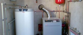
Electric boilers
A fairly common alternative to gas and solid fuel boilers. Lots of advantages, high efficiency, but long payback period. The connection is simple, like with gas boilers, but without a cold water supply. Temperature regulation and overheat protection are provided.
Mechanical boiler timer
Using a simple mechanical timer for an electric boiler, there are three options for starting the central heating system:
- The boiler is turned off;
- The boiler supplies warm water;
- The boiler turns on and off at the set time.
Mechanical timers usually have a large round dial with a 24-hour scale in the center. By turning the dial, you can set the desired time, and then leave it in that position. The boiler will turn on at the right time. The outer part consists of a set of tabs for a 15-minute period, which are inserted for easy adjustment of operation and mode settings. Emergency reconfiguration is possible, which is performed with the boiler connected to the network.
Mechanical timers are easy to set up, but the boiler always turns on and off at the same time every day, and this may not satisfy the owners if the family is large and bathing procedures are carried out several times a day at different times.
Schemes for connecting heating elements to a single-phase network.
Tubular electric heaters are designed for a specific power
and
voltage
, therefore, to ensure the nominal operating mode, they are connected to a supply network with the appropriate voltage.
According to GOST 13268-88, heaters are manufactured for rated voltages: 12
,
24
,
36
,
42
,
48
,
60
,
127
,
220
,
380 V
, however, heating elements designed for voltages of 127, 220 and 380 V are most widely used.
Let's consider possible options for including heating elements in a single-phase network.
2.1. Plugging in.
Heating elements with a power of no more than 1 kW (1000 W) can be safely plugged into an outlet through a regular plug, since the majority of electric kettles and boilers that we use to heat water have this power.
in parallel via a regular plug
two heating elements, but both heaters should have a power of no more than 1 kW (1000 W), since when connected in parallel their total power increases to 2 kW (2000 W). Thus, you can turn on several heaters, but their total power should be no more than 2 kW, and to plug into an outlet you must use a more powerful plug.
There may be a situation when you have several heaters lying around at home, designed for an operating voltage of 127 V, you can’t throw them away, and you can’t plug them into the home network. In this case, the heaters are turned on sequentially
, which makes it possible to apply increased voltage to them. When two heaters with a voltage of 127 V are connected in series, their power remains the same, but the total resistance doubles. For example, when two 500 W heaters are turned on, their total power will be 1000 W.
However, this scheme has one drawback: if any of the heating elements fails, then both will not work, since the electrical circuit will break and the power supply will stop.
You must also remember that when two heaters with an operating voltage of 220 V are connected in series, their total power decreases
twice as much, since due to the increase in total resistance, each heater will receive about 110 V instead of the required 220 V.
Purpose of thermostats
Depending on the purpose of the room, it can be different, but not higher than +27°C. Although in some cases, when heating large rooms, heating up to +33°C is allowed.
Even a novice specialist can connect the thermostat
There may be several main reasons for maintaining the temperature within such limits:
- Providing comfortable conditions for a person, because when the floor is heated above +27°C, the sensations for the feet can be far from pleasant.
- Floor covering also requires maintaining certain temperatures, non-compliance with which can lead to various unpleasant moments - deformation, drying out, divergence of seams.
- And the constant unregulated operation of the heating element will result in a significant waste of electricity.
It is in order for the temperature to be maintained within certain parameters that electric underfloor heating systems are equipped with thermostats. Moreover, the scheme for connecting a heated floor to a thermostat is quite simple and will not cause problems even for a person who is faced with such a need for the first time. This is clearly visible in the figure.
Connection diagram of the floor to the thermostat
Start and stop buttons
When starting and stopping the engine using a starter, it is convenient to connect a device with buttons connected in series with the device.
To ensure that the engine does not stop working after pressing the “start” button, self-retaining is introduced into the circuit due to the terminals paralleled with the “start”. Thanks to them, the engine runs after the “start” button is no longer pressed, until the stop button is pressed.
Voltage is supplied to the motor through any contact marked with the letter L, and it is removed from the corresponding contact under the letter T. This connection diagram is valid for a single-phase network.
Main types of boilers and temperature control
There are several types of boilers: solid fuel, gas, electric and liquid fuel.
Boilers have become widespread throughout the world. There are domestic samples, and there are also imported boilers. Material of manufacture: steel or cast iron. Easy to use, economical, with the function of adjusting the coolant temperature. In cheaper models, this function is implemented using a special device - a thermoelement.
Structurally, a thermoelement is a metal product, the geometric dimensions of which decrease or increase under the influence of temperatures (depending on the degree of heating). And this, in turn, changes the position of a special lever that closes and opens the draft damper. The photo shows an example of such a regulator:
Photo: thermostat sample
The more the damper is open, the stronger the combustion process, and vice versa. Thus, the volume of air that enters the closed combustion chamber is completely controlled by the thermostat, and if necessary, its supply is stopped and the combustion process is extinguished. More modern models are equipped with controllers that, depending on the specified thermal conditions, control the air flow, turning on (or off) a special fan (see photo below):
Boiler with temperature controller
Gas boilers are the most common and cheapest units to operate. Boilers are single-circuit and double-circuit. Single-circuit boilers have one heat exchanger and are intended for heating only. The connection diagram is shown in the figure below:
Switching diagram for a single-circuit boiler
Double-circuit boilers have two heat exchangers and are designed for heating and producing hot water. The boiler switching diagram is presented below:
Switching diagram for a double-circuit boiler
Some boilers have separate controls for heating and hot water temperatures.
Thermostat for a heating boiler (thermostat): which one is better to choose
Before buying a thermostat for a boiler, you need to decide on the type of device. To do this, you need to understand the fundamental difference between the models of mechanical room thermostats and electronic ones. There is an opinion that the latter are difficult to configure and they are unreliable, but this is not the case.
An electronic thermostat is more accurate and has flexible settings.
Replacing the contactor in an electric boiler with a modular version
Hello to all readers of my site!
Continuing the topic of electric boilers for the home, I want to tell you one story from practice.
A client came to me asking for help in solving a problem.
The electric boiler installed at home turned on/off very loudly during operation.
A boiler with three heating elements with a power of 6 kW, connected to one phase, that’s what I found out in advance over the phone.
There is also a simple automatic temperature control that operates on/off. contactor, which makes loud “slaps” when switching.
Everything would be fine, but the electric boiler is installed not in a separate boiler room, but in the kitchen not far from the bedroom and it really interferes with rest... Imagine - sleeping at night and you are woken up by periodic “BA-BANG!”, “BA-BANG!” )))
Having found out all this, I went to the place to see what could be done to help in this case, how to make the electric boiler silent.
It turned out that the electric boiler had already gone through one contactor replacement; before that, a small-sized KME contactor with a rated contact current of 20 amperes was installed (according to the owners). It broke down and was replaced with exactly the same but larger size - KME-3210.
This is why they changed the contactor, as they explained to me - one heating element on the electric boiler stopped turning on and the contactor sparked strongly during operation. This contactor only worked for a short time and its contacts burned out, the connection of the electrical circuit was broken and the current to one heating element stopped “passing”, naturally this heating element stopped heating.
This surprised me a little, since the load of three heating elements for the starter was fully consistent, 6 kW is approximately 28 amperes, and the contacts of the contactor were paralleled and only the phase was switched through them, and it turns out that a current of up to 60 mA could flow through three contacts for a long time time without any consequences.
And here it turns out that from half the permissible current of 30 amperes the contacts failed...
Something is wrong here. Just in case, I check the resistance of the heating element with a multimeter (by the way, they are connected in a star configuration) - everything is fine, the resistance is the same as it should be, because the heating element is of the same power, 2 kW each.