The chandelier not only complements the overall design of the room, but also serves as a source of light in the dark. However, the maximum possible level of illumination is not used very often, right? For the most part, there is a need to use the economy mode, when only part of the lamps are functioning.
For this purpose, connect the chandelier to a double switch, which allows you to adjust the intensity of the room lighting. Do you want to install the switching device yourself, but don’t know how to do it correctly?
We will help you understand all the nuances of this process - the article provides diagrams for connecting the device to a switch with two keys, and discusses the main mistakes that beginners make. Correct connection of the wires will allow control, providing comfortable lighting.
The article contains photographs, diagrams and recommendations in video format on how to correctly connect a chandelier on your own. Having studied the basic rules and installation diagrams, you can begin to work.
Safety first
Work with electrical wiring must be carried out in compliance with safety precautions and following a clear sequence of actions.
First of all, the rules concern de-energizing the wiring during the process of fitting and stripping wires, installing the operating mechanism of the switch, connecting conductors to terminals and other actions.
The main aspect that you should pay attention to when performing home electrical work is contact with exposed wires. All actions must be performed after turning off the general switch and using special tools
However, to determine the required wire, you will still need a power supply, so you must be as careful as possible in your work and perform all actions only with special tools with high-quality insulation of the handles.
The figure shows that 3 conductors are suitable for the double switch, one of them is directed from the distributor, and the rest are used for contact with the chandelier. The electrical wiring is aluminum and is represented by a three-core wire
Installation of a double switch is carried out only in the phase conductor gap.
When inspecting the completed circuit, it is allowed to turn on and off the lighting fixtures only after complete isolation of the exposed conductors and their final fastening.
Chinese chandeliers: what is special
Chinese chandeliers are distinguished by the fact that their build quality leaves much to be desired. Therefore, it is better to check each chandelier with a continuity test so as not to get a short circuit.
It is equally important to check the quality of the insulation. To do this, connect all the wires into one twist, take a tester, and check whether the bare parts of the wires touch the body. If the insulation is poor, then it is better to take this lighting device for exchange.
There is no way to do this without checking the connection of each light bulb. To do this, a light bulb is screwed into each socket one by one and checked for integrity of the connection. With the bulbs unscrewed, the device should show a high resistance (infinity), but with the bulbs screwed in, only a few tens of ohms.
Then you can start connecting all the conductors, depending on the groups formed.
Application of double switches
Connecting the chandelier to the electrical circuit with a double switch allows you to both turn on a group of lamps one by one and turn on the lighting device at full power.
In this case, a two-phase device can operate by interacting only with two groups, the number of lamps in which is not limited.
Using a two-key device, you can connect any two lighting groups that require parallel or alternate activation. In this case, the scheme undergoes virtually no changes
Such control fittings can be used in a private house, where the first line supplies external lighting, and the second - the corridor, also in apartments, distributing power between two bathroom rooms.
A two-key switch is a pair of single-key switches equipped in one housing, so the connection diagram is almost identical.
To reproduce the installation plan, you must first become familiar with the design features of the product and the elements connected to the electrical network.
Connection diagram for two or three chandeliers from a single switch
In a large room, several chandeliers or a large number of halogen lamps and LED lamps are often installed, which are all turned on simultaneously with one single switch. Also, sometimes it becomes necessary to install a switch so that it can turn on the lighting in several rooms simultaneously. In this case, parallel connection of chandeliers is used, like several shades in one chandelier.
Device design with two keys
There are a lot of modifications and types of light switches. However, two-key electrical accessories gained popularity relatively recently, when lighting began to be reproduced using multi-lamp chandeliers.
Thus, the need arose for light distribution through zoning with spotlights.
No. 1 - self-clamping terminal block model
The device body has standard parameters. Depending on the modification, it can be overhead or built-in; it can be easily mounted on the external or internal part of the wall.
The second type is equipped with adjustable clamps. Using screws, the device body is secured in the desired position.
The design of the two-key device contains two independent mechanisms, through which the connection and disconnection of the electrical network circuit is carried out
To fasten wires, modern fittings use plate clamps or a clamping strip with screws.
The screwless model has become widespread and is simply indispensable for self-installation for beginners. The connection diagram and pin distribution are in most cases shown on the back of the case. Conventional labeling values are also used.
The main symbol is the Latin letter L, meaning contact for the phase wire. Nearby there are a pair of arrows pointing down. They are interpreted as indicating the direction of the two outgoing phases. The numbers indicated in place of the arrows carry the same meaning.
In this German two-position switch, the phase wire is connected to the terminal marked L, and the outgoing phases facing the corresponding keys are connected to terminals 1 and 2
The double contacts of the first switch key are located on the left side, and the second one on the right.
Based on the connection method, each of the keys can provide voltage in different directions, for example, turn on several lamp bulbs or illuminate a room located nearby.
Each of the conductors has its own purpose, so the best option is to use a cable with cores of different colors. This will significantly simplify and speed up the electrical installation process.
No. 2 - connecting a screwless model
The process of connecting self-clamping contacts is much simpler compared to screw contacts. First of all, turn off the electricity supply. Next, all conductors of the future contact must be stripped of 1 cm of insulating material.
Each contact provides for the fixation of one pair of cores. The stripped wire is inserted all the way into the corresponding hole in the mechanism.
After turning on the electricity, you need to calculate the power phase. An indicator screwdriver is used for this purpose. After checking, the current supply must be stopped.
Checking the presence or absence of a phase on the contacts is carried out through special windows, which are provided in the two-phase switch mechanism
Following the diagram indicated on the back of the working part of the switch, it is necessary to connect the multi-colored wires one by one, distributing them among the keys.
Let's look at a detailed action plan using a specific example.
From the electrical panel of the apartment, the power supply enters the distributor in the form of a pair of wires: the phase indicated in red, and the zero – blue. There may also be a yellow-green ground wire next to them.
In our example, the red power phase is connected to the red wire that goes to the common contact of the two-position switch. The output from it already produces two wires - burgundy and yellow.
The burgundy wire is directed into the junction box. There it is connected to a contact identical in color and goes to the first group of chandelier bulbs.
According to the diagram, the yellow phase contact going into the distributor must be connected to a wire of a similar color going to the second group of lamps.
The zero, shown in blue in the diagram and also coming from the apartment's electrical panel, goes directly to the distribution box, and then to the terminal block, where the zero of each group of chandelier lamps is connected.
Similar to the zero vein, there is a yellow-green one, which is responsible for the ground.
Be sure to check the reliability of the contact clamp - you need to lightly tension the cable. If there is a need for any corrections, you should press the button on the end of the desired contact. In the picture L is a contact for connecting a phase
When installing and connecting a double switch, its operating mechanism is hidden in a socket box, secured in the desired position with a screw fastening. Next, keys and a decorative overlay are placed on the device.
No. 3 - installation of screw contacts
In this case, there are no schematic instructions. Visually, it is necessary to identify the two lower contacts, which most likely represent the outgoing phases, and the upper one, the supply phase.
You can verify the correctness of the actions by methodically turning the contacts on and off: when the keys are on, the circuit is closed, in the off position, the circuit is opened.
Depending on the manufacturer, the terminal designations may differ. In this Chinese switch, the marking is presented as follows: L - common phase, outgoing phases L1 and L2
The mechanism of this type of switch is equipped with three screw contacts through which the cores are connected, and two screws that activate the spacer tabs.
The power phase (1) sits on the top single contact, the two bottom contacts connect the outgoing phases of the lamp (2), the spacer screws are located on the right and left sides of the device (3)
For screw-type contacts, it is necessary to strip the cores by 0.5 cm. The cores are fixed using a plate driven by screws.
Helpful information
Let us immediately point out some features that can help:
- Breaking the circuit with a switch is carried out only through the phase line, and the neutral conductor and grounding conductor (if any) go directly to the consumer;
- For each branch, a separate phase wire is laid at the output of their switch (It is separated in the switch itself. A single-key switch has one phase conductor at the output, a two-key switch has two, a three-key switch has three). This affects the wire used leading from the switch;
- On the terminal blocks of the chandeliers you can find the designation of the terminals, which makes the connection easier (the marking “L” indicates that the terminal is phase, “N” is neutral, “PE” is grounding).
Now directly, how to connect the chandelier to the switch.
Let's assume that the line is made in advance, the switch is in place, and 2 or 3 wires stick out from the ceiling (with the third wire being “ground”).
In general, the connection diagram is the simplest - “one-key switch - 1 lighting fixture.”
If the chandelier is armless (with 1 lamp), then the connection method does not differ at all from powering a simple light bulb.
Also, connecting a chandelier to one or more bulbs is greatly simplified by a multi-channel wireless switch.
Checking the correct connection of wires
The first priority is to inspect whether the switch was connected correctly. On one of the lines, the voltage indicator in the open position should indicate the presence of phase potential.
At the place where it is planned to install the chandelier, two wires should come out, namely the neutral and phase wires coming from the switch.
The number of conductors in the device itself will be greater, especially when a multi-track lamp is connected. It is also possible to have a grounding conductor if the house uses electrical wiring with a TN-CS grounding system.
If the check failed to detect a phase, this indicates an incorrect wiring connection or problems with securing the wires in the operating mechanism of the switch
To correctly assign the purpose of each cable, it is necessary to check whether they have voltage. There are several special devices for this: indicator, voltmeter, digital multimeter, etc.
It is not difficult to work with the voltage indicator: you just need to touch its tip to the area of the wiring that has been cleared of insulation.
Only one cable does not illuminate the device - zero, the rest, when in contact with a screwdriver, will cause it to glow - phase. Alternately switching two keys of the switch will help to recognize that the wire belongs to the desired key.
In addition to zero and phase, grounding is additionally installed in new buildings. The yellow-green wire is connected to a similar lamp cable
A similar determination method is used when measuring with a digital multimeter. It must be set in the “Volts” mode and set the scale to more than 220 V. Alternating, you need to touch the pairs of wires with the probes.
The phase pair will not lead to changes on the device dial. By connecting a possible phase and zero with probes, you can see the number 220 V on the indicator. If the wiring has the same color, it is better to mark it with markers.
Preparatory operations
Such operations are associated with the fact that it is necessary to call all the wires for connection. This is especially true for those who do not deal with electricity constantly. As a rule, from 2 to 3 wires can stick out on the ceiling, and very rarely - four wires, and they are actually not needed, since even 2 wires are enough. If 3 wires still stick out, then one of them is grounding. If you know where the neutral wire is, where the phase wire is, and where the ground wire is, then there should be no problems connecting the chandelier.
Grounding
Grounding conductors are found in new buildings, as well as in apartments after major renovations, with the replacement of electrical wiring. As a rule, it is distinguished by a green-yellow color. It is connected to the same conductor, which is located on the chandelier, although not all chandeliers have a similar wire.
There is a grounding wire in houses that are newly built or recently renovated.
It happens that there is no such conductor on the chandelier, so the grounding wire on the ceiling is insulated and left unconnected, otherwise, if it is not insulated, it may accidentally touch the phase wire and then a short circuit will result, since the grounding wire is always connected to the neutral wire.
Phase and neutral conductors
The working, main conductors are considered to be “phase” and “zero”. In old houses, all wires have the same color. In new houses or in houses after major renovations, electrical wiring is carried out with multi-colored wires, which simplifies the connection process. Unfortunately, this does not always happen and it is better to be on the safe side once again by calling all the wires: there are all sorts of electricians and they do not always adhere to certain rules. This is especially true in relation to private specialists, who often do not even have documents allowing them to carry out such work.
To determine which wire is which, you can use either a multimeter or an indicator screwdriver, with which you can easily identify the phase conductor. If there are 3 wires on the ceiling, and they are switched by two switches, then there should be 2 phase wires and one neutral. Switches should be turned on/off alternately to determine which phase conductor is associated with a specific switch key. Once the purpose of all the wires has been determined, you can begin connecting the chandelier, having first turned off the circuit breaker on the lighting panel for reliability, although it is enough to turn the switch keys to the “off” position and check the presence of voltage on the phase wires using an indicator screwdriver. As a rule, phase conductors are switched with switches, as they are more dangerous.
Checking the wires on the ceiling with a tamper
In the photo you can see what technology is used to determine the wires in the presence of a multimeter. First of all, you should move the switch on the multimeter to the position where alternating voltage is measured, choosing a measurement limit greater than 220 V. When testing two phase wires, the multimeter will not show anything, so we can safely say that the third wire is zero. Then control measurements are made, connecting the third wire and each of the wires determined in advance as phase wires to the multimeter in turn. The device should show a voltage within 220 V. If the wires do not have different colors, then the neutral wire can be marked, for example, by sticking a piece of electrical tape.
It is much easier to call all the wires using an indicator screwdriver: if the indicator lights up, then it is a phase wire, and if not, then it is a neutral wire. All that remains is to mark them.
Using an indicator screwdriver to find a phase
If there are 2 wires sticking out on the ceiling, then these are “phase” and “zero”, although sometimes it is important to know which of the two conductors is phase. As a rule, on some modern chandeliers, o and “L” are placed on the terminal blocks, so it is advisable to connect the neutral wire to the “N” terminal, and the phase wire to the “L” terminal.
Decoding the markings of electrical wires
For ease of identification and to avoid confusion, the insulation of the cable cores is different colors. According to the standards, the ground wire is yellow with a green stripe.
Such a conductor is found in new buildings, where a high level of protection against electric shock is provided.
In houses with old wiring, deciphering the purpose of the cable is difficult, because... Previously, the color of the insulating material was the same. To begin electrical installation work, you will need to ring the cable (+)
The marking of the neutral conductor is carried out by an insulating sheath of blue or light blue color, in which the core is enclosed. Any other shade variations other than those indicated can be used for the phase.
Compliance with safety rules when connecting a chandelier
Working with live parts always involves a certain amount of risk. Connecting a chandelier to a home is no exception, and the work is done at height. To protect yourself and others during electrical installation work, you must follow the following safety rules:
- Carefully study the instructions for connecting the chandelier.
- The power tools used in the work must be in good working order, especially with regard to the insulating parts of the tools.
- Equipment for climbing to heights - stepladders and other devices - check for reliability and stability of the structure.
- Before starting work, stop the power supply by turning off the circuit breakers in the electrical panel.
Connection options
Connecting a chandelier and other lighting devices is done by crimping, soldering or using terminal adapters.
The first option involves connecting the conductor cores by crimping them with a fixing sleeve. The entire procedure is carried out with a special tool - press tongs. This method complies with all regulatory documents.
The second method is considered one of the most reliable, but difficult to reproduce. It is practically not used due to the inconvenience of working at height.
When choosing one of the methods for contacting conductors, you must remember that aluminum under constant load acquires plasticity. Connections of this type require regular inspection. You also need to periodically tighten the fixing bolts.
You cannot twist aluminum and copper wires together - a galvanic pair is formed, which, even with a slight increase in the level of humidity in the apartment, can reproduce an electrochemical reaction in the form of oxidation.
This process breaks the contacts, and the junction begins to heat up. It is for this reason that fires occur.
If you use terminals to connect, you will need to remove 9-11 mm of insulating material from the conductors. For this purpose, there are special marks on the clamps that determine the required level of stripping.
The use of terminal blocks is considered relevant. At the moment, the model range of this connecting element is quite wide - from the classic screw version to the spring modification.
Connecting a chandelier to a single switch
The easiest way to connect a chandelier. The wires of the home electrical wiring and the wires of the lamp are connected in pairs to each other.
Execution sequence:
- Connect the neutral wire of the chandelier with the neutral wire from the junction box.
- The phase wire from the distribution box must first be connected to the switch and routed under its button. Connect it to the phase wire of the chandelier.
When connecting wires, the most reliable and safe option is to use screw terminals. However, in practice, twisted connections are often isolated with special caps. We strongly do not recommend using PVC tape for insulation; after time, due to its drying out, the quality of the insulation can deteriorate significantly, which can cause a short circuit and is fraught with unpleasant consequences.
How to connect a chandelier correctly?
If you pay attention to the five-arm chandelier, it has a fairly large number of wires, so inexperienced craftsmen avoid such lighting devices.
However, there is nothing complicated in the process of connecting the wires coming from the distributor to such a lamp.
Since the determination of the phase of the wires is carried out when the power supply is turned on, it is necessary to ensure that the bare ends of the wires do not touch. If necessary, they must be carefully moved in different directions, having first turned off the shield
First of all, you need to deal with the wiring on the ceiling, which in a standard situation has three wires:
- L1 - phase of the first switch key;
- L2 - phase of the second key;
- N - zero.
If the wires are the same color, then using a voltage indicator, the identity of each is determined, i.e., phases L1 and L2. Accordingly, the remaining core will be zero.
Next, you can move on to the process of forming contact nodes. Let's consider the example of a five-arm chandelier, which has 10 wires: brown phase conductors - there are 5 of them, and the same number of blue zero wires.
Most Chinese-made chandeliers are not equipped with the necessary connections, so you will initially need to determine how many groups the light bulbs will be divided into. Each lamp socket has two conductors of different colors - black or blue and brown
This lamp has one undeniable advantage - the combination of light bulbs can be made at your discretion. According to the diagram described below, the first group includes two light bulbs, the second - the remaining three.
Wiring diagram for a five-arm chandelier. Explanation of symbols: L - phase of the general power supply of the switch, L1 and L2 - phase wires of a series of light bulbs (red), neutral cable N - blue
Based on this diagram, the connection of a five-arm lighting device is carried out in several stages. Initially, a pair of brown wires is assembled into one unit.
It is advisable that lamps included in the same series are connected in parallel. We call this twist L1.
The next step is to twist the unused three brown wires in a similar way. This will be the L2 series. Next, the resulting two nodes are inserted into two-wire terminal clamps WAGO .
It is better to make all contacts using terminal clamps rather than by twisting. You can use either a common clamping module or an individual design
At the next stage, the blue wires are twisted and connected to a three-wire terminal.
The order of connection does not matter. The combination can be 3+2 or 2+3. This will be the neutral node - N.
The only disadvantage of Vago terminal blocks is that they are not treated with quartz paste, which protects the contacts from oxidation. However, this problem can be solved by purchasing such a composition and douching it into the clamp yourself
As a result, the output produces 3 connection nodes: the phase of the first and second groups of lamps - L1 and L2, the common neutral node - N. Taking into account the marking of the wires, they must be connected to the corresponding lines on the ceiling.
There are two phase conductors coming out of the lamp (L1, L2), and there will be only one neutral wire (N) and it is connected to the second contact of the socket
At the final stage, it is necessary to lay all the wiring in the block of the chandelier bowl and install it. Fastening is carried out in one of the following ways: hung on a hook or screwed with screws. Next, the decorative plugs of the lamp are tightened.
What is taken into account before carrying out work?
Let’s immediately identify a few key points that should definitely be taken into account:
- Design of a chandelier (They are usually divided among themselves by horns - elements at the end of which sockets for light bulbs are installed. As mentioned above, the division into power branches for light bulbs is made at the entrance to the chandelier, and the horns can be considered these branches. By design, chandeliers are hornless, two-, three-, four- and five-horn);
- The switch used (the method of connection depends on this. If, for example, the switch is a single-key switch and when the light is turned on, all the lamps of the chandelier will light up, then this is one connection diagram, but the use of two- or three-key switches, each key of which will be responsible for the operation of a specific group lamps require the use of a slightly different connection method);
- The presence of additional equipment in the design of the chandelier (a fan or a remote control unit makes certain adjustments to the connection diagram);
- Features of the electrical network of the house (in old buildings, two-wire wiring is usually used, and in new or restored buildings the number of wires is already three).
And one more thing - it’s one thing to simply remove the old lighting fixture and connect a new one in its place, and quite another thing to completely create a lighting power line, including laying wiring from the distribution board, installing switches, junction boxes and lighting fixtures, and then connecting them into one network.
We will not delve into the specifics of independently installing the power supply branch of a chandelier, since we are more interested only in how to connect the lighting elements, although some points regarding wiring will be touched upon.
Using a ground wire
When arranging electrical communications in new houses according to generally accepted standards, there will definitely be a grounding wire in the wiring.
In such rooms, when installing a chandelier, you can find that 4 wires come out of the ceiling: two phases from the switch, zero and ground.
The ground wire is marked with a combination of yellow and a green stripe. In a single-phase network it will be the third residential, in a three-phase network - the fifth
Most models of chandeliers with two groups of lamps and metal parts include a terminal block through which the grounding connection is made.
During the installation of the lighting device, you need to pay attention to this and connect the wire.
Wires on the chandelier
At the location of the chandelier (ceiling) there are wires to which this lighting fixture must be connected. As a rule, these are three conductors.
- Blue – zero N.
- Brown – L phase.
- Brown – L phase.
The fourth wire can be yellow-green - PE ground. It is connected to the chandelier body.
There may be several of them, the coloring must comply with the standards.
Connection options
You can connect a chandelier with 2 wires (phase and neutral) to a single-key switch, or to one key of a multi-key switch.
You can connect a chandelier with 3 wires (zero, phase, phase) to a 2-key switch. There can be from 2 to ten or more lamps on a chandelier, but there will be 3 operating modes.
You can also connect a chandelier with 4 wires: zero, phase, phase, ground to a two-key one. If the earth comes out of the ceiling, then the earth of the chandelier is connected to it. If not, then this chandelier wire is not connected anywhere, it is simply isolated.
A three-arm chandelier is connected like this:
The following modes are possible here: one, two or three lamps are on (1+2). It is clear that there are no other options.
Three blue wires - zeros on the chandelier are collected together (into one bundle) and connected to the zero that comes out of the ceiling.
There remain 2 brown ceiling wires and 3 of the same color that come out of the chandelier. Two chandeliers (any) are assembled into a bundle and connected to the ceiling phase conductor. The remaining one is connected to the second phase ceiling wire. You can check how everything works.
If it doesn’t work, you need to check the presence of phase and zero (with the switch on), the integrity of the wires, lamps and contacts of the chandelier. It is advisable to do this before connecting. There are no other reasons.
The connection points are insulated, the wires are hidden behind a decorative cover, and the chandelier is hung on a hook. The connection is complete.
Connecting a five-arm chandelier
The connection is similar: five blue wires are collected together and connected to the zero, which comes out of the ceiling. Then 2 groups of lamps are determined that will be turned on by the right and left switch keys. The brown phase wires in these groups are connected together.
Then a bundle of 2 brown wires from the chandelier is connected to one of the phase wires that come out of the ceiling, and a bundle of three is connected to the second.
Typically, the phase wires on a chandelier are connected so that the lamps in the group are located not next to each other, as in the figure, but across one. This way the chandelier will glow more aesthetically.
If there are 6 or more lamps on a chandelier, they are still connected into two groups. In the picture above, the 6th, 7th, 8th and so on lamp is simply added. To any group - optional.
Correct connection of the lamp
The lamp base is connected like this. The phase comes to the side contact, zero - to the bottom.
The logic of this particular scheme is simple. If the switch is in the “off” position, no phase is supplied to the lamp. There is no danger of electric shock when unscrewing a burnt-out lamp and screwing in a new lamp.
If the switch opens zero, the phase will be supplied to the cartridge constantly. This is a direct violation of the electrical installation rules (PUE). Such cases occur if careless electricians delve into the distribution panel and, without the knowledge of the owner, swap phase and zero.
Connecting a halogen lamp
Chandeliers with halogen-type lamps do not always operate from a 220 V alternating voltage network - these can be products designed for an alternating voltage of 6, 12 or 24 V. Therefore, in the second case, a step-down transformer will be needed.
Sometimes the manufacturer in each model of a lighting device operating on halogen lamps builds in special transformers to reduce the current.
In this case, the circuit is already assembled and all that remains is to install it. 2 cables remain unused, which are connected to the ceiling wiring, and the connection is made arbitrarily.
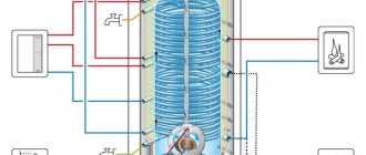
The diagram shows the principle of connecting a chandelier with an electronic transformer. This variation of the lamp has a controller unit. On the back of its case there is a connection plan. In the diagram: PE - ground, N - zero, L - phase
Chandeliers, which include a remote control, can be of various modifications: with halogen, LED or incandescent lamps.
There are also models of combined type. This device is complicated by the presence of a radio control unit. Essentially, this controller is a wireless device that is controlled via a remote control or a standard key switch.
Connecting such a lighting device is carried out similarly to the previous model, however, another wire will be added here, the thinnest of all.
This is an antenna through which the communicating actions of the remote control and controller are reproduced. It remains unchanged inside the glass of the chandelier.
Purpose of using a two-button switch
Assembling and connecting a chandelier with 2, 3, 4, 5 or more arms through a two-key switch aims to divide the lamps into 2 groups. This provides 3 operating modes:
- When both keys are turned on, all chandelier lamps work.
- When you turn on the right key, a group with fewer lamps works.
- When you turn on the left key, a group with a large number works.
This flexibility allows not only to save electricity, but also to create light comfort in the room that suits the situation.
Conclusions and useful video on the topic
The entire process of preparing the chandelier for connection and directly connecting the double switch to the power supply is described in the video:
Inexperienced craftsmen quite often make mistakes during the electrical installation process; see which ones and how to avoid them in the video:
If you correctly reproduce all stages of installation and follow the diagram, you can protect yourself from unpleasant consequences when directly operating the lighting device. Moreover, you will be able to create a unique light atmosphere in the room, adjusting it to your needs.
Share with readers your experience of connecting a chandelier to a double switch. Please leave comments on the article, ask questions and participate in discussions. The feedback form is located below.
LED chandelier with remote control
In the age of electronics, running multi-core cables along the walls in order to command a chandelier from different points in the room? Not worth it.
The market is filled with modern lamps with main and backlight lamps, which are controlled from a remote control: basic, portable.
When installing such a chandelier, the switch will only perform the function of supplying voltage to the controller, which is hidden behind the decorative cup of the lighting fixture. The most common type of connection with the remote control is a radio channel.
Before connecting an LED chandelier, you need to understand its structure. The electrical part includes the following.
- Receiver-switch (controller) for the signal and switching on Wireless Switch lamps (in one case, with a connection diagram and an outgoing antenna).
- Transformers, drivers, power supplies (when using low-voltage lamps and LEDs).
- Sources of light.
As a rule, a purchased chandelier has internal wiring done. The user only needs to connect neutral and phase to the controller. The latter comes from the switch.
Here they are in the photo, in the lower left corner.
The diagram looks like this. There are three consumers here. Two are halogen lamps, one is LED.
By pressing buttons (usually 4) from the remote control, the lamps are turned on/off according to the instructions. If the remote control cannot be used, a switch will play its role. The chandelier reacts to quick on-off switching from one to four times in the same way as to commands from the remote control.
To attach such a chandelier to the ceiling, use a special DIN rail.
For a detailed description of how to connect a chandelier with a remote control, watch the video:
Single-key switch circuit
First, let's look at a simpler diagram - how to connect a three-arm chandelier with 3 wires. Here are three detailed step-by-step instructions. First, check the equipment of your lamp:
- Having opened the original packaging, immediately find the list of kits included in the chandelier and check the list for the presence of all components.
- Find the bracket that will attach the chandelier to the ceiling. It is a strip that is directly screwed to a wooden base in the ceiling, and the chandelier cover will be attached to this strip.
- Check the presence and integrity of all lampshades.
- Next, there should be a device (you can call it a chandelier connection box) in which the wires will be disconnected, three horns are attached to it, and this mechanism itself is connected to the bracket cover. A double wire (phase and neutral conductors) is pulled through this device. One end of it will be connected to the phase and neutral conductors, which come out of the hole in the ceiling, the second end is intended to connect to the conductors in the horns.
- Usually the third grounding wire comes separately with the lamp. On the metal case (most often on the lid) a special icon indicates the place where the protective grounding should be connected.
- Check for the presence of three horns; cartridges should be attached to them and a phase and neutral conductor should come out of each.
Now let's look at how to connect the wires in a chandelier:
- Take one horn and the connection box of the lamp where the connection will be made. Two wires come out of the horn (blue - zero, brown - phase). Pull them through one of the three holes and secure the horn.
- Do similar actions with the other two horns.
- As a result, in the connection box of the lamp there were 6 wires from the horns - three blue and three brown, and a double 2-core wire that will be used to connect to the network.
- Strip the insulation on all 6 wires from the horns and on the double wire.
- Connect the three blue wires to one core of the double wire, and in the same way connect the three brown wires to the second core of the double wire. Do this using twisting, you can also solder it on top. Put on the insulating caps, as a rule, they are included in the kit.
- Carefully lay all the wires in the connection box of the chandelier and close the lid on top.
- Connect the protective ground wire at the indicated location.
All that remains is to connect our chandelier with three wires to the network:
- Before starting the electrical part of the work, de-energize the room by turning off the power supply.
- Attach the mounting frame to the wooden structure in the ceiling using ordinary wood screws. This must be done as firmly and reliably as possible, because the bar will have to support the full weight of the chandelier.
- To avoid having to redo anything later, immediately try on the lamp, lightly tightening the decorative bolts. Look, if you are satisfied with everything, then unscrew the bolts and start connecting the wires.
- It is advisable to do this work with a partner, so that one person can hold the lamp to be connected, and the other can handle the connection. If there is no partner, then secure the lamp to the installed bar, tightly tying it with a cord or a piece of strong wire.
- Start by putting self-clamping terminal blocks on the wires sticking out of the hole in the ceiling. Then connect the corresponding lamp cores to them.
- Now turn on the machine and switch to check proper operation. If all three lamps light up, turn off the switch, the circuit breaker and finish the job by finally screwing the lamp to the bar.
Now you know how to properly connect a chandelier with three arms, let's look at a more complex option - connecting a chandelier to a double switch.