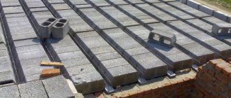
Such structures do not have load-bearing beams, but are installed on load-bearing wall structures or on supports.
Their task is to be strong, to give rigidity to the building frame and to evenly distribute the load over the entire surface of the floor in a house, apartment or office.
In civil and industrial construction, three types of beamless floors are used: prefabricated, precast-monolithic and monolithic. They can be installed not only on walls, but also on load-bearing columns. Then they cantilever beyond the boundaries of the capitals.
As a rule, this scheme is used for large industrial buildings. The design of beamless floors is carried out on the basis of an equal-span grid in the shape of a rectangle or square.
Recently, an increase in the volume of construction of multi-storey monolithic buildings has led to the fact that beamless floors have become more in demand, since they have the lowest installation cost with high load-bearing characteristics of the structure.
A little history
Beamless floors were first used in the construction of a building in 1902 in the USA by engineer Orlano Norcours. In Russia, such designs were also used at the beginning of the last century. The first such house in our country was built in Moscow in 1908. It was a four-story building for a dairy products warehouse. It was built under the leadership of engineer A.F. Lopeit. A feature of buildings of this type was that the columns in them had an extended top. This increased the contact area between the supports and the slabs and increased the reliability of installation. Therefore, at the beginning of the century, ceilings of this type were called “mushroom-shaped”.
You may be interested in: Double Taxation Agreement with Cyprus: definition, application and essence
Recommendations for selection
When choosing reinforced concrete beams, you need to focus on the basic properties and characteristics, the required parameters. Among the main ones, the following are usually taken into account: steam/hydro/sound insulation, heat protection, fire resistance. As for the size and dimensions, it is also important to determine the main indicators.
The design of reinforced concrete products must meet the requirements as much as possible in accordance with the design of the element/structure. So, for a wall frame on a columnar foundation, the weight of a solid floor on reinforced concrete beams will be enormous. At the same time, hollow beams in a solid house will not guarantee the required level of building safety.
During the installation process, structures must accurately calculate all compressed and tensile zones that affect the strength of reinforced concrete.
During the construction of the interfloor slab, the reinforcement in the reinforced concrete beams must be located precisely in the tension zones. This will give the required level of reliability.
Where are they used?
You might be interested in: Do I need a current account for an individual entrepreneur? Banks for individual entrepreneurs. Individual entrepreneur without a current account
Such floors can be installed in buildings of almost any type. Very often, beamless structures can be seen, for example, in urban residential slab high-rise buildings. Also, in many cases, this is how floors are made in production workshops, warehouses, garages, etc.
In particular, such structures are often installed in food industry enterprises. These could be, for example, dairies, workshops for the production of semi-finished products, etc. That is, most often beamless ceilings are installed where there are increased hygiene requirements.
In private housing construction, interfloor structures of this type are used quite rarely. But sometimes suburban residential buildings are built this way.
Installation and Installation
All work with reinforced concrete beams is relatively simple. You need to be able to accurately record them, understanding the features of the structure. First of all, before installation, preparation is carried out - all axle rails are coated with paint, parts are cleaned.
Typically, reinforced concrete beams are installed with a crane, lifting them using the mounting loops provided during casting, which are attached to the slings on both sides (2 fasteners on each). The size of the slings depends on the length of the beam itself.
Installation of an I-beam is carried out from a vehicle: the beam is lifted using traverse hooks, supported by guys (so as not to hit the column with a heavy structure), and, if necessary, leveled with a jack.
Reinforced concrete crane beams are mounted on prepared special gaskets and secured with bolts. Then geodetic alignment is performed and the structure is finally fixed.
Subject to the correct choice based on correct calculations and high-quality installation, reinforced concrete beams can provide the necessary strength characteristics of the structure, guaranteeing its durability and reliability.
Main varieties
In construction, there are only three types of such floors:
- prefabricated;
- monolithic;
- prefabricated monolithic.
The first type of structure consists of two parts: a slab located above the column and a capital. The configuration of beamless prefabricated floors is relatively simple. In this case, the slab rests on special shelves arranged above the column. The latter, in turn, are supported by the capitals and connected to each other by welding.
How to pour slabs onto load-bearing walls of a house
The monolithic floor slab is poured with a concrete mixture prepared from the following ingredients:
- Portland cement marked M400;
- gravel or crushed stone up to 3 cm in size;
- purified sand.
The concreting process includes the following steps:
- Supplying the concrete mixture into the formwork with reinforcement.
- Uniform distribution of concrete over the area of the future floor.
- Compacting a concrete mass using a mechanical vibrator.
Monolithic and prefabricated monolithic structures
You may be interested in:What is urban planning: concept, architecture and governing bodies
The second type of beamless floors is monolithic. They are used where smooth ceilings are needed. For example, they are very widely used in underground passages and subways. Such floors are flat, continuous slabs supported by columns. The latter in this case also have capitals.
A feature of prefabricated monolithic beamless floors is that they are designed with a square or rectangular grid of columns. Most often, the supports are installed according to the 6x6 m pattern. Such floors are laid on prefabricated, span and above-column panels.
Method of Professor A.F. Loleita
Both the upper and lower reinforcement bars are laid in the form of networks that are not interconnected. The lower network is constructed from straight rods 80% of the span length. In this case, even rods reach the support axis on one side, and odd rods on the other. The strip above the line of columns is reinforced first, and then between them. But this is if the floor slabs are long and rectangular. And if they are square, then it makes absolutely no difference which direction the reinforcement goes first.
Scheme of reinforcement with non-welded mesh
With rectangular slabs, the strip above the columns on the long side is reinforced first, then along the short side, the strip above the long side of the span is reinforced next, and finally the short side of the span is last. The peculiarity of the reinforcement of the outer panels is that the rods of the strip are first laid over the columns, which are perpendicular to the frame, then the same strip, but parallel to the frame. After this comes the turn of the span, the reinforcement of which also proceeds first perpendicular to the strapping and then parallel. In above-column strips, the reinforcement is always laid in the bottom row, which is done by slightly bending the reinforcement laid second. The third row reinforcement bars of the span are also bent, which means that only the bars from the span, laid last, are in the second row. The strips of upper reinforcement on the supporting strips are located perpendicularly. To correctly position the upper net, so-called “fillies” (linings) are used. They are connected with a thin knitting wire to both the upper and lower meshes.
Reinforcement scheme according to the A.F. method Loleita
Method A.F. Loleita, when reinforced with separate meshes, requires a higher consumption of metal than the same method of separate reinforcement with rods. In addition, preparing such meshes in production, tying them with binding wire and transporting them to the installation site also brought many problems. But the situation has changed over time. The fact is that after the introduction of industrial methods for the production of reinforcing mesh, their preparation, cutting, welding and with the introduction of various lifting equipment capable of delivering assembled structures to the construction site, the Loleit method again became quite cost-effective, in demand and is taken into account. In addition, the use of different types of steel and methods of its processing helped reduce metal consumption in general. Thus, the method of preliminary production of reinforced meshes is actively used today.
Capless ceilings
This type of construction is also quite popular among builders. In this case, the floor elements rest directly on the pylons and columns of the frame. The slabs in such structures most often have a constant thickness.
Such floors began to be used in the construction of buildings in 1940. A feature of beamless structures of this type is the reduced area of support of the slabs on the columns. To absorb shearing forces in this case, the technique of transverse reinforcement of beamless floors is additionally used. Steel rods significantly increase the strength of the slabs in the area where they adjoin the supports.
Also, when designing buildings of this type, large diameter columns can be provided. When using such elements, the contact area between supports and slabs increases. Consequently, loads cannot destroy the floor in the area of the columns.
Fragment of a monolithic ribbed floor (a) and a grid of breakdown into slab and beam elements (b)
1 - plate; 2, 3 - secondary and main beams; 4 - columns; 5 - slab element; b - beam element of T-section
The dimension of the created finite element mesh is determined by the overall dimension of the problem (the number of finite elements and nodes in the overall spatial diagram), the geometric dimensions of the structure and configuration (dimensions in plan, regularity of the structure of the supporting system, the presence of curvilinear elements, etc.). In regular structures, labor intensity is reduced at the stage of forming the calculation model and in the process of analyzing the results obtained. It should be remembered that the geometry of the design diagram is formed along the axes of the elements. Accordingly, the forces in the zones of nodal interfaces are determined based on actual spans and are somewhat overestimated. At the same time, in a real system, the internal forces along the lines of mating elements are significantly influenced by the dimensions of the structures, which must be taken into account when designing the reinforcement of sections.
Loads on the floors are specified according to the actual scheme of their application in the structure. Loads from the structure's own weight are taken into account by specifying the volumetric mass of the material. Loads from equipment, depending on the nature of the interaction with the floor, are taken in the form of concentrated, linear or uniformly distributed. Loads from snow cover are specified as uniformly distributed, taking into account changes in intensity at the locations of snow bags. Temperature effects are set using the temperature difference for the entire structure, its part along the length or cross-section. Wind load is most often represented as a horizontal concentrated force at the slab level.
Calculation of the strength of floor elements based on the finite element method is generally carried out as linear (beam elements) and planar elements under the action of forces in these elements, obtained from the spatial static calculation of the load-bearing structural system as a whole.
The design forces for linear elements are Nx, NY, Qz, Mx and My applied at the element boundary, for slab elements - the combined action of bending moments Mx and My in the direction of mutually perpendicular axes X and Y and torque moments Mxy applied on the lateral sides of the flat selected element, under the action of transverse forces Qx and Qy applied on the lateral sides of the flat element (Fig. below).
Types of frames
Buildings with beamless floors can be constructed using different technologies. The frames of such houses are:
- framed;
- communication;
- frame-braced.
In systems of the first type, the main load-bearing functions of the floors are performed by columns and crossbars mounted in two directions. The frame elements in such buildings are rigid frames. The latter absorb all the loads acting on the building - both vertical and horizontal.
In braced frames, the main loads fall on systems of columns and diaphragms, also called pylons. The role of the floors themselves in such buildings increases greatly. In addition to the actual vertical loads, these structures in this case also perceive horizontal ones, after which they transfer them to the diaphragms.
You may be interested in:Bank guarantee: types, terms, conditions and features
Combined frame-braced frames are usually used in load-bearing structures made of steel and monolithic reinforced concrete. In this case, diaphragm systems absorb 85-90% of horizontal loads. Moreover, with a little strengthening, they can withstand them completely, 100%.
Regulatory Requirements
Beamless floors are complex structures, the reliability and durability of which determine the performance characteristics of the entire construction project. They are subject to dozens of regulatory and subregulatory government acts in the field of urban planning:
- GOST 2590-2006;
- GOST 27751-2014;
- GOST 380-2005;
- GOST 535-2005;
- GOST 6727-80;
- GOST 7473-2010;
- GOST 7566-94;
- GOST 8267-93;
- GOST 8731-74.
First of all, their action is aimed at ensuring safety requirements for various design impacts during the construction and operation of buildings:
- GOST 10180-2012;
- 10181-2014;
- 10922-2012;
- 12730.0-78.
Therefore, when designing structures, any possibility of destruction must be excluded so as not to cause harm to the life and health of people, property and the environment:
- GOST 13015-2012;
- GOST 14098-2014;
- GOST 17624-2012;
- 22690-2015.
SP regulations N: 2.13330, 14.13330, 20.13330, 22.13330, 28.13330 and 131.13330 impose special requirements for beamless floors in terms of maximum loads, deflections, deformations, fire resistance, moisture resistance, frost resistance. All indicators are normalized depending on the climatic and seismological characteristics of the development area .
Advantages
Compared to conventional ones, beamless floors have a number of undoubted advantages. The advantages of such structures include primarily:
- low labor intensity of finishing work;
- reducing the height and cubic capacity of the building;
- sanitation.
Finishing smooth beamless floors is much easier than regular ones. In this case, you don’t even need to file the ceiling. All that is needed to finish such a floor is plastering the surface and further painting. However, both of these operations will not take too much time.
Beamless reinforced concrete floors are usually thinner than traditional ones. Accordingly, with the same cubic capacity, the building will be lower.
Characteristics and parameters
Beamless floors must:
carry the required design loads without damage;- have rated steel, not bend under the load of its own weight and located equipment;
- possess the calculated heat, sound, moisture and biological protection, meet all SES and fire safety requirements;
- have initial characteristics to prevent the formation and excessive opening of cracks and other defects that disrupt the normal operation of the floors;
- have a service life no lower than that established for the wall structures of the building.
In order for all the requirements of regulatory documents to be met, and the resulting reinforced concrete products to comply with GOST 27751, it will be necessary not only to correctly design the structure and install it, but also to use source materials whose characteristics will comply with SNiP standards.
The main standardized and controlled characteristics of the production quality of concrete are considered:
- The optimal grade of concrete is M300-M400, and if operating conditions require it to withstand large flows of water, then grade M450-M500.
- Compressive strength class: B2-B5.
- The standard axial tensile strength of concrete must correspond to 0.95 MPa.
- Frost resistance grade F is responsible for the safe number of freezing/thawing cycles; it must be no less than that of wall structures and can be in the range F=100-300.
- The waterproof grade W is set according to the highest water pressure that concrete 15 cm thick can withstand. For example, W2 does not allow water to pass through when a slot 20 m high is pressed on it. (2 bar), and W12 can accordingly withstand 120 m.v.st. For the production of beamless slabs, water resistance grades from W2 to W12 can be used.
- The mobility of concrete “P” is not lower than class 4 to guarantee high-quality filling of the reinforced structure.
- The optimal grade for medium density D300-D600 corresponds to the compressive strength class B2-B5.
What other advantages are there?
It is much easier to maintain the surface of beamless floors. Indeed, in this case, the ceiling or floor structure does not have any cracks where debris or dust could get clogged. Accordingly, various types of pathogenic microorganisms do not grow in such ceilings. That is why structures of this type are usually installed in food processing plants or, for example, in hospitals.
Installation procedure for beamless SMP
The construction of buildings with emergency treatment facilities is carried out strictly floor by floor. The installation of the floor itself is carried out upon completion of the installation of the columns, which is preceded by the installation of embedded parts in the floor of the lower floor. Columns can also be mounted using the split principle, however, this technology is often abandoned due to the significant length of the tongue-and-groove connection.
After installing and aligning the grid of supports, the heads are installed on their widening. Next is the installation of belt formwork, designed to hold the concrete mass while pouring the dowels. Over-column slabs are laid on top of the capitals and joined in a manner specified in the concrete concrete configuration. Interspan slabs are laid on top of the slope slabs, usually narrowed in the support area to facilitate monolithic work.
After installing the prefabricated elements, additional reinforcement cages are tied into the monolithic joints and embedded parts are installed under the columns of the next floor, if necessary. After this, the technological grooves are filled with concrete grade B15, which shrinks using the vibration method. At this stage, the complexity of installing floors using the BBSMP technology becomes obvious: in addition to the fact that it is necessary to carefully select products from the range, it is necessary to provide all the conditions at the construction site for carrying out work using two different technological processes using a wide range of construction equipment, often heavy.
What are the disadvantages
Of course, such floors also have disadvantages. The main disadvantage of structures of this type, in comparison with beam ones, is their heavy weight. Supports for this type of ceiling must be installed as strong as possible.
Also a disadvantage of beamless structures is the limited span width. The distance between the supports for such floor slabs should not be too large. Reinforced concrete is a very durable material. But with a large area and serious load, such a slab will still begin to sag and may even collapse.
It is considered economically feasible only to install beamless floors in spans no more than 5x6 meters wide with a load of 5 kN/m2. In this case, the structures usually turn out to be quite reliable.
Designing beamless floors is a rather complex and very responsible procedure. Only an experienced, highly qualified engineer can perform such work. Difficulties in drawing up drawings, of course, can also be attributed to the disadvantages of such structures.
Design diagram of the secondary beam (a) and envelope diagram of bending moments (b)
The loads on the main beam are considered to be applied in the form of concentrated forces from the weight of the secondary beams, slabs g and the live load P collected from the corresponding load areas. To simplify the calculation, the self-weight of the main beams also results in a concentrated load applied in the axes of the secondary beams. The design diagram of the main beam is also a continuous structure with design average spans taken equal to the distance between the axes of the supports (Fig. below, a). The location of the live load (across the span or in adjacent spans) is considered in several combinations in order to identify the maximum span and support bending moments in the section of the main beam (Fig. below, 6).
Features of the calculation of beamless floors
Floors of this type should therefore be designed as carefully as possible. In conventional structures of this type, the load is carried by many fairly short joists. The slabs have a larger area, and therefore can bend more.
How do you calculate beamless floors? As already mentioned, such structures are most widely used in construction, mounted over spans of up to 5-6 m. If the distance between the supports is greater, designers usually have difficulty ensuring the shear strength of the slabs.
The ceiling begins to collapse in this way around the column. The concrete in this place loses its integrity, which can lead to an instant collapse of the slab. There are several ways to increase the punching strength of a structure:
- by increasing the working thickness of the slab;
- by increasing the support area;
- by installing transverse reinforcement.
There are several methods for calculating beamless monolithic, prefabricated or prefabricated monolithic floors. For example, in construction the technology of calculating the total bending moment is often used.
Also, the design of beamless monolithic floors can be carried out using more accurate and modern technologies. For example, one such technique is called moment estimation.
Average prices
Prices for installing beamless floors sometimes vary several times; they depend on the construction volume, the height of the work, as well as on the adopted floor model. The most accessible and prefabricated systems for the private sector are prefabricated monolithic systems, the most expensive are monolithic ones using capitals.
Average prices for installation and materials for beamless floors:
| № | Name of work/product | Dimension | Cost per unit, rub. |
| 1. | Capital KP 1-1-1, 2980x2980x600 mm, 1.8 m3 | PC. | 36500 |
| 2. | Monolithic floor with reinforcement and formwork | m3 | 7300 |
| 3. | Installation of a monolithic ceiling using a profiled sheet | m3 | 5600 |
| 4. | Installation of prefabricated monolithic floors: | ||
| 4.1 | Metallized beam “Homeowner” from 1.0 to 4.0 m | 1 m.p. | 730 |
| 4.2 | YTONG steel beam up to 9m | 1 m.p. | 1300 |
| 4.3 | Expanded clay concrete block liner 200x520x200 | 1 PC. | 90 |
| 4.4. | Assembly work | m3 | 4200 |
Old technology
This technique for performing calculations when installing beamless floors is used quite often in our time. In this case, the first thing engineers take as a basis is that the forces on the capitals are distributed along a triangle. The design span of the panels is taken to be the distance between the centers of gravity of the panels. The total total bending moment in this case can be calculated using the following formula:
- M = 1/8 WL(1-2c/3L)(1-2c/3L).
Here W is the total load on the cell of the beamless floor slab, L is the distance between the columns, c is the dimensions of the capitals.
This formula was derived by J. Nichols in 1914. Already in 1917 it was adopted as one of the ACI building standards. This formula is used to calculate floors with capital columns.
Calculation of savings during work
This modular frame solution makes it possible to use standard equipment, provides additional filling and thus constitutes an alternative to the traditional solution. If we compare the location and number of columns in both methods (traditional and with hollow balls), then in modular construction the following are taken into account: spans to be covered, the number of columns and the consumption of building materials. Hence the conclusion is that modular construction is quite profitable and when using it, it is possible, by reducing the number of columns, to increase spans and reduce the cost of materials.
With modular construction of the frame, it is possible to reduce the number of columns, save reinforcing steel, concrete consumption, and increase spans.
Having made the calculation, we can notice that with modular construction with built-in plastic balls, the number of columns will be reduced by 40%, reinforcing steel, reinforcement and concrete consumption for arranging the foundation will be saved by 20%, and concrete consumption will be reduced by 32% per unit of flooring. At the same time, the calculation shows that when erecting a beamless floor, the arrangement of purlins and beams accounts for almost 100% savings in concrete, and the time for formwork work is reduced to 65%.
Work on arranging the floors begins with the installation of racks and flooring (horizontal) - this is the initial stage for further work on installing reinforcement and formwork. After the reinforcement and frames with built-in plastic balls are laid out, concreting work begins. They are produced with a mixture that fills the space between the balls, covers the surface of the reinforcement and is located above the balls at a distance of the thickness of the protective layer. The supply and uniform distribution of the cast concrete mixture is carried out using a concrete pump.
In order to ensure that the supply and distribution of concrete is carried out evenly throughout the entire floor and at the same time the labor intensity of the work is reduced, companies use flexible hoses (concrete pump) made of synthetic material that has been reinforced. This makes it possible to complete concreting work quickly and accurately. The mobility of the mixture is from 7 to 10 cm. If the speed is higher, then during pumping the stream stratifies and plugs form. If plasticizing additives are used in the mixture and casting technology is used, then it becomes necessary to increase the consumption of cement and the amount of sand (fine fraction) in the concrete mixture.
Evaluation of moments
This somewhat more modern technique was developed based on both experiments and theoretical data. In our country, V.I. Murashov and A.A. Gvozdev were involved in its improvement in the 30s of the last century.
For a square panel, the formula in this case is as follows:
- M0=1/8 WL(1-2c/3L)(1-2c/3L).
In order to determine moments in design sections and when designing reinforcement, floors using this technique are divided into spans and above-column strips in plan. Moreover, they do this in such a way that the width of each such part is equal to half the distance between the axes of the columns in all directions.
In each such strip, negative and positive aspects arise during the operation of the building. Moreover, in above-column elements they are usually larger than in span elements. Based on the width of the strips, the moments are determined from the curves. However, in practice, their stepwise measurement is used. In this case, the moments are assumed to be constant across the width of the strips.
With various types of plastic deformations, redistribution of M can also occur. Therefore, the values of the moments in the four design sections of the slabs are determined so that their sum is ultimately equal to the beam M0.
Types and reinforcement of capitals
Drop structure
If the structure does not provide for strapping beams, then the outer columns must be supplemented with half-capitals (wall-mounted). There are currently only three types of capitals - a capital with a capital plate, a straight capital (that is, without a capital plate) and a capital with a break. The second type of capital is used in cases where the calculation shows that the loads are relatively small, while the rest are intended for high loads. The most widespread is the capital with a break, as it can withstand the greatest loads, and is also architecturally more attractive. Back in the 30s of the last century, large-scale research and testing of beamless flooring methods with various types of capitals was carried out. These tests confirmed the preliminary calculation and showed that the capital with a fracture is stronger than other types by an average of 10%. It was precisely because of this difference that in the USSR it was recommended to use a capital of this type. Calculating the size of capitals has the peculiarity that the actual and calculated sizes are not the same thing. The calculated width of the capital C is the diameter measured at the lower level at the plane of the slab. Calculation of the dimensions of capitals is an important point in any design and is verified by calculation of the main tensile moments of tension of the slab along its perimeter. For average design loads, the best ratio of the size of capitals to the span is 0.35 with a design value of 0.2. In most cases, reinforcement is not required, since the cross-sectional area of the capital is such that both tensile and compressive forces do not exceed the calculation limits allowed by building codes. Therefore, reinforcement is, as a rule, not used to strengthen columns.
Reinforcement of capitals without kinks is carried out with rods with a diameter of 10 mm, installed in the corners and the middle of the sides.
Reinforcement is justified only as an improvement in the combination of column and slab or other structural desires of the customer. Reinforcement of capitals without kinks is carried out with ordinary 10 mm rods installed in the corners and the middle of the sides. In general, the same reinforcement practice applies to capitals with a break and half-capitals. If a capital slab is used, it is not reinforced; reinforcement of the capital itself is quite sufficient. When using metal columns, capitals are usually abandoned, replacing them with metal beams at the junction of the slab and column. In this case, the support area is increased without significantly reducing safety. But this solution makes it more convenient to lay various communications, especially pipelines.
Features of slab installation
The technology for assembling beamless floors depends primarily on their type. When using reinforced concrete slabs, the construction method is as follows:
- production of slabs at the enterprise;
- loading them onto vehicles and delivering them to the construction site;
- unloading slabs by truck crane at the construction site;
- installation of slabs on columns and walls of a building using a truck crane.
It is believed that the length of reinforced concrete slabs cannot exceed 9 m.
Reinforcement with welded mesh
This is the most industrial and convenient method of reinforcement during construction, and it is also the most economical in terms of metal consumption. When using welded mesh, there is no need to bend the hooks at the ends of the rods. Cold-drawn steel wire is used as reinforcement material. Because of all these advantages, welded mesh has become so widespread. When reinforcing both beamless and other types of reinforced concrete slabs, they have become an almost universal means. Welded meshes are connected to each other, according to building regulations, with certain joints.
If you want to make your own calculations of specific loads and types of reinforcement used, we advise you to refer to specialized literature and standards, especially pay attention to the works of M. Ya. Shtaerman and A. M. Ivyansky.
Installation of monolithic ceiling
Such structures are poured in pre-assembled wooden formwork. The bottom of this shape is also made of planks. It is supported from below with special telescopic supports. After this, fill as follows:
- install the fittings on special mushroom stands;
- concrete mixture is poured into the formwork.
The mortar is prepared at enterprises with strict adherence to all required technologies in terms of proportions and uniformity. It is fed into the formwork using a hose from a tanker truck.
The mold from the ceiling poured in this way is removed after about 2 weeks. During this time, the slab is watered daily with water from a hose in order to prevent the appearance of surface cracks. Further construction of the building will begin no earlier than in another two weeks. It takes at least a month for concrete to gain sufficient strength.
Source
How a panel frame is formed using permanent formwork
Formwork for a monolithic floor slab is made on the basis of the following building materials:
- moisture-resistant plywood, the thickness of which is 2-2.5 cm. The laminated coating of the plywood will facilitate its dismantling after the solution has hardened;
- smooth boards made from durable lumber. To assemble the shields, use boards whose thickness is 4-5 cm and width 18-20 cm;
- telescopic metal supports or ordinary logs with a diameter of 15 cm. Racks are used to ensure the immobility of the formwork;
- wooden beams used to support the formwork frame. The beams perform the function of transverse elements of the formwork structure.
To assemble the formwork, also prepare hardware and the necessary carpentry tools. Do not forget about the building level, which allows you to check the horizontalness of the structure.
The construction of a monolithic floor slab assumes that concrete will be poured into horizontal formwork
When assembling the formwork, follow the sequence of operations:
The formwork structure must be dismantled 4 weeks after concreting.