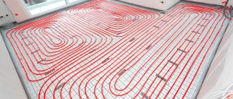
Currently, most residential owners prefer to use warm water floors for heating. The efficiency of this design depends on proper coolant flow.
Adjusting the flow meter of the underfloor heating manifold will allow you to monitor water consumption in the pipeline and fine-tune the system.
This device can facilitate the balancing process and rationally distribute liquid over the heating circuits, thereby creating uniform heating of all rooms.
The essence of the collector
The main feature of a water heated floor is the coolant; the water gradually moves to the heating circuit and gives off part of its energy.
That is why the heating of the floor occurs with the release of heat to the air that is mixed inside the room, and it, as is known, is directed from the bottom up. A number of devices are responsible for supplying warm water to the circuit and intensity:
- the valve is considered the main one;
- a pump must be present;
- collector.
All control of water distribution is carried out using a flow meter. It is this device that plays the main role in the operation of the entire system.
All collectors are designed specifically for hot water, and they are also necessary to collect waste material. In the unit itself, the process of mixing hot water that comes from the source and return takes place.
Thanks to rotameters, there is a chance to ensure that the entire volume of water reaches the floors. Simply put, the equipment will independently control the heat in the water field.
Floor heating cannot do without a rotameter. The design includes a body made of plastic, but there are models made of brass. A float is placed inside any device. There is a flask with a scale.
The float can move up and down and at the same time points to a certain division of the scale. Judging by it, it will be possible to judge the volume of coolant that circulates in the pipeline.
If we talk about theory, the system works without a device, but in this case the adjustment has to be done manually, relying on your own sensations.
The flow meter for the underfloor heating manifold plays an important role; if it is abandoned, the following problems will arise:
- the fact is that in the absence of a flow meter, some floor contours can be supplied with coolants, while the features of the room will not be taken into account;
- the energy consumption used to operate heating devices, for example, either gas or electricity, will be excessively increased.
Let's say you plan to simultaneously heat the bathroom and another room, for example, a bedroom. A gas-powered boiler will heat water for the bathroom and bedroom absolutely identically, that is, there will be one temperature regime.
It is important to install the equipment correctly; to do this, you need to screw the device itself into the collector socket. Fixation occurs due to the nut. When improving a heated floor, it is advisable to try to control the length of the heat pipeline of all circuits, without paying any attention to the configuration. This will simplify the adjustment of the system and it will still be possible to achieve normal temperature parameters.
But we must take into account that the bathroom is small in size, in order to heat it you need less water from the boiler, but more water is required to supply the bedroom. It is possible to compare the heat of each room, but only in this case will you need to use a flow meter.
If you use this device, the temperature will be set in the bathroom and bedroom for a comfortable stay there.
Having carefully assessed the principle of operation of this device, we can draw the following conclusions:
- the device can function completely autonomously, without the need to use any additional power sources;
- the main operating principle of the flow meter makes it possible to sufficiently consume the coolant for the circuit and further significantly reduce the energy costs of all heating devices;
- the design of the entire device is capable of providing control over the amount of water entering the pipes;
- the manifold, which is installed together with the flow meter, makes it much easier to control the operation of the entire system in general. Also, installation of the system is not complicated and does not require special maintenance.
Collector heating device
In construction, radiant heating is widely used. Here, separate pipelines are laid to each radiator. This allows you to regulate the air temperature in each heat exchanger.
Photo 1. Manifold for heating systems. The arrows show the components of the device.
It is in the beam system that the collector is used. It has the following characteristics:
- Provides automatic removal of air from the heating system.
- Disables a separate radiator.
- Turns off a group of radiators if necessary.
- Distributes heated coolant to radiators and underfloor heating pipes.
- Returns the cooled coolant to the pipes of the heating boiler.
The beam system also uses at least 2 combs, the combination of which is called a collector. One comb is responsible for the heated coolant , the second for the cooled one .
Reference. Not only the collector can turn off heating devices, but also individual taps that are located directly on the radiator.
A flow meter or thermostat and other elements are installed on the comb body
How to choose a location for installation?
In multi-storey buildings, collector groups should be installed on all floors ; this simplifies checking the serviceability of devices and regulating their operation.
The groups are mounted in special niches, which are located at a small height from the floor.
The niche also accommodates combs and fittings.
In the absence of niches, collector groups are placed in any premises with the necessary humidity. A corridor, closet, or storage room are suitable for such purposes
The equipment is covered with special cabinets, overhead or built-in. Holes for pipes are made in their side walls.
System calculation
The formula for calculating collector heating is as follows:
S0 = S1 + S2 + S3 + Sn.
In this formula, S1 - Sn is the cross-sectional area of the outgoing branches, where n is the number of branches. S0 is the cross-sectional area of the comb.
Before applying the formulas, the number of heating circuits is determined, a drawing is made, and only then calculations are made.
After applying the formula, a final version of the diagram is drawn up, in which additional devices are taken into account and each individual group of pipelines is indicated.
How to calculate the correct pipe diameter?
To create an effective heating collector, it is not enough to just build a circuit. It is also necessary to determine the correct diameter of the pipes.
When choosing pipes, consider:
- Hydraulic losses . If the system uses pipes of different diameters, this will inevitably lead to hydraulic losses.
- The speed of the coolant. The water should not cool down before it reaches the last radiator.
- Coolant volume. Pipes with a larger diameter reduce fluid loss, but at the same time it increases the cost of heating the coolant.
It is also important to carry out the calculations correctly, this will help increase the efficiency of the entire heat supply system.
The formula for calculation is as follows:
m = P x V
When calculating the optimal pipe diameter, it is recommended to use special programs . They will make the result more accurate.
Purpose and types
A warm water floor is distinguished by a large number of pipe circuits and a low temperature of the coolant circulating in them. Basically, heating the coolant to 35-40°C is required. The only boilers that can operate in this mode are condensing gas boilers. But they are rarely installed. All other types of boilers produce hotter water at the outlet. However, it cannot be run into the circuit at this temperature - a too hot floor is uncomfortable. To reduce the temperature, mixing units are needed. In them, in certain proportions, hot water from the supply and cooled water from the return pipeline are mixed. After which, through the manifold for the heated floor, it is supplied to the circuits.
Manifold for underfloor heating with mixing unit and circulation pump
To ensure that all circuits receive water at the same temperature, it is supplied to a heated floor comb - a device with one input and a number of outputs. Such a comb collects cooled water from the circuits, from where it enters the boiler inlet (and partially goes to the mixing unit). This device - supply and return combs - is also called a manifold for heated floors. It can come with a mixing unit, or maybe just combs without any additional “load”.
Design and principle of operation
A mixing valve is a device for mixing and regulating water flows; it has three openings: two inlet and one outlet. In the space between the inlet holes there is a heat-sensitive damper; it is responsible for regulating the movement of liquid - cooled and heated. Modern devices are equipped with a thermal head or control valve.
The heating floor valve operates continuously. The step-by-step process is as follows:
- heated water is supplied to the first inlet - its temperature is determined in the valve;
- if the heating degree of the water exceeds that required for heated floors, then the supply of cooled liquid from the return line opens through the second hole;
- inside the valve, heated liquid is mixed with cooled liquid;
- after obtaining the desired temperature, the return flow is closed;
- The coolant is supplied through the outlet to the underfloor heating pipes.
For the thermal valve to work effectively, it is necessary to maintain constant pressure in the line.
When operating an automatic thermo-mixing tap equipped with a servo drive, heating is carried out in 3 minutes ; if there is a thermal head, the liquid is heated in 15 minutes .
How does the collector work?
Water floors are laid in various ways, for example, concrete or flooring, but regardless of the technology chosen, it is necessary to purchase and install a manifold cabinet.
In the future, two pipes will be inserted into it:
The cyclical nature of the process is ensured by another built-in component of the system - a circulation pump. One way or another, during the operation of a heated floor, say during repair work, the system has to be turned off. To do this, each of the pipes is equipped with shut-off valves. A plastic pipe and a metal shut-off valve are connected to each other through a compression fitting. Then a comb is connected to the valve, mounting an air vent on one end and a drain valve on the other. After assembling the cabinet, they proceed directly to installation. And only with a comb already installed on the wall can you cut the circuit pipes to length.
Results
It is important to ensure that when the water floor heating system is operating, the flow rate on the collector is visible. This is necessary for maintenance. Each water circuit must have its own flow meter.
We recommend: How to check underfloor heating?
As you can see, in the equipment, each element performs its own functions, so each one needs to be given sufficient attention, and in order for the entire system to work as one whole, it is worth equipping it with a flow meter and a collector, which will evenly distribute all the heat.
- Related Posts
- How to set up a heated floor?
- How to connect a warm water floor in a house from a gas boiler?
- What kind of liquid should be used for underfloor heating?
- What kind of base can be used for a heated floor?
- How to install a film heated floor?
- How to lay heated flooring under laminate on a concrete floor?
Warm floor and the space occupied by the manifold with flow meters
The peculiarity of a heated floor as a heating system is that the heated coolant, moving along the heating circuit, transfers part of the thermal energy to the floor surface. Thus, by heating the floor, heat is transferred to the air mass circulating inside the room in the direction from bottom to top. A number of devices control the supply of warm water to the heating circuits, the intensity and flow rate, including:
- three-way valve;
- circulation pump;
- collector.
The distribution of the coolant is controlled by a flow meter for heated floors. This device plays one of the key roles in the operation of the entire pumping and mixing group. Heated floor collectors are designed to supply hot water and collect waste coolant for its further use in the heating system pipeline. In the pumping and mixing unit, hot water coming from the heating source is mixed with the coolant returned to the circuit - return. The functionality and efficiency of heated floors is based on this operating principle.
Mixing unit with rotameters for a warm water floor system
Together with the operation of safety valves, rotameters are designed to regulate the temperature of the coolant in individual circuits of the water floor. Thanks to these devices, the required volume of prepared water entering the warm water floor system is ensured. In other words, this equipment monitors the amount of coolant in the water heating pipe, and therefore the functionality of the entire heating system.
Automatic and manual temperature equalization
When adjusting a heated floor using the mixing and limiting method, the methods for setting the required coolant temperature are slightly different. It also matters whether the proportional adjustment is done on the fly or whether the adjustment is done manually. The latter is permissible only for the mixing control method and only on the condition that the coolant flow in the remaining circuits of the system changes insignificantly.
Manual adjustment of a three-way valve requires temperature control on the return branch, for which a thermometer sleeve or an attached temperature probe can be used. Temperature measurements should not be taken immediately, but based on the length of the loop and the coolant flow in it. The temperature must be measured after a time sufficient for 2 or 3 times renewal of the coolant in the heated floor system. The purpose of the adjustment is to ensure a constant difference in coolant temperature between supply and return. In this case, the temperature difference is determined by the heated floor design and is calculated by the thickness, screed material, as well as the direction and pitch of the coil pipes.
Automatic proportional control is much simpler. The main control element is the RTL thermostatic head or unibox valve. The larger the mark at which the flywheel is installed, the higher the coolant temperature will be, which is true when adjusting both by mixing and limiting.
Typical connection diagrams
Water heated floors are rarely used as the only source of heating. Heating only due to underfloor heating is permissible only in regions with a mild climate, or in rooms with a large area, where heat removal is not limited by furniture, interior items or the low thermal conductivity of the floor covering. Almost always it is necessary to combine radiator circuits, hot water preparation devices and underfloor heating loops in one heating system.
Typical diagram of a combined heating system with connection of radiators and underfloor heating circuits. This is the most technologically advanced and easily customizable option, but it also requires significant initial investment. 1 - heating boiler; 2 — safety group, circulation pump, expansion tank; 3 - manifold for separate two-pipe connection of radiators in a star configuration; 4 — heating radiators; 5 - underfloor heating manifold, includes: bypass, three-way valve, thermostatic head, circulation pump, combs for connecting underfloor heating circuits with gearboxes and flow meters; 6 - heated floor contours
There are quite a large number of variations in the design of the boiler room piping, and each individual case has its own principles of operation of the hydraulic system. However, if you do not take into account very specific options, then there are only five ways to coordinate the operation of heating devices of various types:
- Parallel connection of the underfloor heating collector to the main line of the heating unit. The insertion point into the main line must be made up to the connection point of the radiator network; the coolant supply is provided by an additional circulation pump.
- Association according to the type of primary and secondary rings. The line, wrapped in a ring, has several supply connections in the supply part; the coolant flow in the connected circuits decreases with distance from the heating source. Flow balancing is performed by selecting the pump supply and limiting the flow with regulators.
- Connection to the extreme point of a coplanar manifold. The movement of the coolant in the heated floor loops is ensured by a common pump located in the generator part, while the system is balanced according to the principle of priority flow.
- Connection through a hydraulic separator is optimal when there are a large number of heating devices, a significant difference in flow rates in the circuits and a significant length of underfloor heating loops. This option also uses a coplanar manifold, but the hydraulic arrow is necessary to eliminate the pressure drop that interferes with the correct operation of the circulation pumps.
- Local parallel loop connection via unibox. This option is well suited for connecting a short-length heated floor loop, for example, if you need to heat the floor only in the bathroom.
The simplest option is to connect a heated floor circuit to a radiator heating system with a coolant temperature of 70-80 °C.
1 - line with supply and return of the high-temperature circuit; 2 - heated floor contour; 3 - unibox. It must be remembered that the nature of the operation of a heated floor may also change depending on the installation pattern of the coil. The “snail” scheme is considered optimal, in which the tubes are laid in pairs, which means that the entire area is heated almost evenly. If the warm floor is arranged as a “snake” or “labyrinth”, then the formation of colder and warmer zones is practically guaranteed. This drawback can be eliminated, including through proper configuration.
Manifold cabinet. Recommendations for location
If you want to hide the manifold assembly, then you cannot do without a manifold cabinet. There is nothing special about it, it is a simple metal cabinet that is mounted to the wall. Inside, it has two vertically fixed strips, which can be adjusted in width to the size of the collector installed on them. There are two types of cabinets: for location against the wall and for location in a niche (recess) of the wall. Also in the cabinet, all heating circuits of the floor are disconnected from other parts of the heating supply of the house and additional equipment is installed. Accommodation
The manifold cabinet should be installed with the expectation of raising the level of the future floor due to its layers. After installing the cabinet, the inlet (supply) and return (return) pipes are inserted into it. The inlet pipe is responsible for supplying hot water (coolant) from the boiler or central heating. The return pipe serves to drain cooled water from the circuit back to the boiler for subsequent heating. Shut-off valves with couplings are mounted on each of the pipes for subsequent connection of the collector.
The location for the manifold cabinet in an apartment or house is chosen in such a way that all the contours of the heated floor have approximately the same length, according to recommendations no more than 70 meters.
Why do you need a flow meter?
Theoretically, it is quite possible to do without installing a flow meter in the manifold. However, if you do not install this device, then:
- Different rooms will have different temperatures;
- There may be excessive consumption of electricity to heat water in the system;
- Different circuits will heat up unevenly.
A simple example can be given: a bathroom and a bedroom. A gas or electric boiler heats water equally for both the bath and the bedroom. But the bathroom is at least 3 times smaller in area than the bedroom. Accordingly, the bathroom will be hot and the bedroom will be cool with the same water supply to the floor heating system. This situation is due to the fact that in the bedroom the total length of plastic pipes in the area is much greater. It is precisely in order to regulate a comfortable temperature in the entire apartment that it is desirable to install such a device.
Advice! When installing a water heated floor, you should strive to make the contours of the pipes approximately the same length. This will save energy costs and allow you to more accurately regulate the temperature.
Principle of operation
The device is installed on the return collector outlets. When the set temperature in the system is reached, the manifold valves narrow the lumen of the energy supply or close it completely. This principle of operation is possible with full automation of the system. For this purpose, the collector is equipped with a temperature sensor.
The flow meter itself consists of several parts:
The flask is usually made of durable glass; the body can be plastic or brass. The float is located inside the flask; it serves as an indicator of the coolant speed. The flow meter is also called a float rotameter.
In an automatic water heated floor collector, balancing of coolant flow is carried out using a temperature sensor. If the latter is not provided, then the rotameter can be adjusted manually.
Equipment and capabilities
Products are manufactured under the Valtec brand by an Italian company. They have been on the Russian market since 2003, so they know our realities first-hand. We produce a wide range of plumbing engineering fixtures and devices. And collectors for heated floors are among them.
general description
The Valtec underfloor heating manifold is made of brass or stainless steel. Or rather, most often, the body is made of stainless steel, and the “filling” is made of brass. In the catalog they are called a manifold block, since there are a couple of devices - for the supply and for the return pipeline. Complete kits are equipped with:
- there are flow meters on the feed comb;
- on the return pipeline there are manual shut-off valves.
Below is the supply and there are flow meters. At the top is the return pipeline, manual valves are installed
In this option, using flow meters, you can adjust the coolant flow in each of the loops, and manual valves on the return pipeline serve to block circulation. But this configuration can be automated. To do this, servo drives are installed on manual valves, which are connected to thermostats installed in the premises. In this way, a constant floor or air temperature can be maintained. Depends on where the heat sensors are installed, because the thermostat reacts to their readings.
An automatic air bleeder is also installed on the Valtec manifold. This is a device that allows you to remove air trapped in the coolant automatically.
Range
All collector blocks for Valtek underfloor heating can be divided into two groups: with and without adjusting flow meters. There are only three options in the first group and two in the second, but in each the number of connected taps is from two to twelve.
- With flow meters on supply
- VTc.594.EMNX. Body - stainless steel AISI 304, fittings - brass CW617N, seals - EPDM 70Sh, number of outlets - from 2 to 12. Operating pressure 8 bar, nominal diameter of manifolds - 1 inch, outlets - 3/4″ external thread, connection - eurocone. Price - from 9 thousand rubles. (for 2 outputs), up to 25 thousand (for 12 outputs).
- VTc.589.EMNX. Manifold for propylene glycol systems. Body - AISI 304 stainless steel, brass fittings and EPDM 70Sh rubber seals. Working pressure 9 Bar, coolant temperature not higher than 90°C. The nominal diameter of the collectors is one inch, the outlets are 3/4 inch with a Eurocone.
Compatibility table for various Valtec manifolds with components
- VTc.596.EMNX. Valtec brass manifold (CW617N brass) with nickel plated. EPDM 70Sh seals, fittings made of the same brass. Working pressure 10 Bar, outlet connection - Eurocone, diameter 3/4″.
- nominal collector diameter 1 inch, number of outlets from 3 to 12. Price from 12 thousand rubles. for 3 exits, up to 38 thousand rubles. for 12 exits;
- nominal collector diameter 1 and 1/4 inches, number of outlets from 4 to 12. Price from 9 thousand rubles. for 4 exits, up to 45 thousand rubles. for 12 exits.
- With manual valves
- VTc.588.EMNX. Stainless steel underfloor heating manifold VTc.588.EMNX with thermostatic valves. Coolant - water or propylene glycol, operating pressure 9 Bar, temperature 90°C. There are manual adjustment valves on the supply side. The number of outputs is from 3 (6 thousand rubles) to 10 (15 thousand rubles), connection via a 3/4″ eurocone, nominal collector cross-section is 1″.
- VTc.594.EMNX. Valtec brass manifold for systems with elevated temperatures - up to 120°C, pressure 10 Bar. Includes manual balancing valves and thermostatic ones.
- nominal diameter of the collectors is 1″, the number of outlets is from 3 (10 thousand rubles) to 12 (27 thousand rubles);
- collectors with a cross section of 1 and 1/4″, the number of outlets from 4 (16 thousand rubles) to 12 (36 thousand rubles).
The basic package includes manifold plugs, automatic air vents, drain valves (for filling or draining coolant), and brackets for installation.
Installation of a system with flow meters
The flow meter is installed on the return of the collector, as recommended by the manufacturers.
However, a feed installation option is possible. The main and important requirement for installing the device is to place it strictly vertically . This facilitates the correct calculation of the coolant level. The collector is placed in a horizontal position.
Automatic operation of the collector and rotameter requires the connection of a temperature sensor. This allows you to block the access of water to the loops when the desired heating degree is reached.
Flow meter installation:
- The device is screwed into the collector socket with a key in a strictly vertical position. The rotameter has an O-ring and a nut.
- Twist and remove the flask by turning it counterclockwise. Remove the ring and return the flask to its original position.
- Turn the brass ring clockwise, bringing it to the desired value, to find the balance of the speed of incoming water.
- Place a cover over the ring to protect it from damage.
At the end of the process, the system is checked for functionality.
Rotameter installation
Let's consider how to correctly install the most commonly used type of water meter - combined with a valve integrated into it. The device is placed strictly vertically: it is simply screwed into the seat, onto the manifold comb on the supply or return. The option is prescribed in the technical documentation and depends on the direction of the liquid inside. The manifold already has sockets for the threads of rotameters as standard, and is often sold already assembled or as a set with them.
Additional sealing materials are not required, but if a leak occurs, they can be used. The standard product has a union locking nut and a polypropylene ring seal.
The traditional appearance of the unit diagram is as follows: water meters with valves on the supply segment, thermostats on the return segment (it can be the other way around).
On the comb of multi-circuit equipment collectors there are seats for each segment, that is, a larger number of water meters are used for each coil that needs to be configured. The device is fixed with a union nut; there may be other mounting options.
If thermostats are installed on the pumping and mixing part, then an additional adjustment to the water meters is also carried out: when the water reaches a certain t°, a valve is activated on the collector return, changing the gap for the flow of water.
The scale of the rotameter flask shows the flow; it is filled with water, the level of which varies depending on the intensity of consumption. There is also a float, which stops opposite the corresponding division. The water meter will immediately show the value, and balancing will be done with a few simple movements.
It is possible to adjust the warm floor contour correctly only if the liquid level in a transparent measuring container with a scale is strictly horizontal. Particular care must be taken to ensure that the device itself is installed exactly vertically. To do this, install the manifold with seats exactly, checking with a plumb line, bubble, and level. However, if the position of the node has deviations, then the system will work normally, but during adjustment it will be necessary to take into account errors.
Flowmeter functionality
A rotameter or, to give a full definition to this unit, a float rotameter, at first glance, is a common mechanical device. The design of the product is based on a plastic case (there are models made of brass), inside of which there is a polypropylene float. The body is equipped with a transparent bulb on which a marking scale is applied. The movement of the float up and down inside the device indicates a certain value on the scale, by which one can judge the volume of coolant circulating in the pipeline system - whether it is enough for the full operation of the heating circuits.
Traditional flow meter for underfloor heating manifold in various versions: on the left - in a plastic case, on the right - in brass.
From a theoretical point of view, the heating system can operate without this device. In this case, you will have to manually adjust the volume of water entering the circuit, based on your personal feelings when the air temperature in the room changes.
- individual circuits of the water floor will be supplied with coolant without taking into account the characteristics of the room, as a result of which the temperature values of the floor surface of heated rooms will differ;
- the energy consumption used to operate heating devices (electricity or gas) will be increased.
For example, you plan to heat the bathroom and children's room at the same time. An autonomous gas boiler will heat water for the bathroom and nursery in the same way, at the same temperature. However, the bathroom is smaller in area and will require less boiler water to heat it than to supply a heated floor in a nursery. You can achieve optimal supply of coolant to heated floors in each room using a flow meter. Consequently, due to the operation of this device, it will be possible to achieve individual temperature values for comfort in the bathroom and children's room.
Assessing the operation and principle of operation of the device, the following conclusions can be drawn:
- the device operates completely autonomously, without requiring additional power sources;
- the operating principle of the flow meter allows you to create optimal coolant flow for heating circuits, significantly reducing the energy consumption of heating devices;
- the design of the device provides visual control over the amount of water in the pipelines;
- the collector together with flow meters for underfloor heating significantly facilitates control over the operation of the entire system, is easy to install and unpretentious to maintain.
Water meter design
The design of the rotameter is mechanical, the material is plastic and/or metal (brass). The upper segment of measuring and adjustment models has a transparent tube with graduation.
There is a float inside, which is why the device is called “float”. This element, fixed to the rod, is supported by a spring (the flow changes the pressure, compresses/decompresses it). At the bottom inside there is a valve connected to the described elements, which changes the flow of liquid according to their position.
Criterias of choice
The quality of functioning of the underfloor heating system depends on the correct selection of the flow meter. Three types of rotameters are produced:
- Measuring. This type of flow meter is installed with a manual adjustment valve. Control is carried out taking into account measurement readings.
- Regulating. It performs only one function - controlling the amount of coolant entering the water circuits.
- Combined. Such a device combines two actions - adjustment and measurement. The cost of the product is significantly higher than that of models performing the same type of functions.
When purchasing a flow meter for heated floors, you should pay attention to the following product parameters:
- Case material. Devices made of brass have high wear resistance. The top of such a body should be covered with nickel. Plastic products are cheaper, but they have a reduced strength rating.
- Device integrity. Before purchasing a rotameter, it is recommended to carefully inspect the housing and transparent bulb to exclude the presence of cracks or other defects.
- Inner part. The spring in the middle of the flowmeter body should be made of stainless steel.
- Flask. The transparent cap with a measuring scale in high-quality models is made of polycarbonate. This material is quite strong and has high heat resistance, which is especially important when used in heating systems.
- Specifications. The instructions supplied with the device indicate the temperature level. This indicator should be no lower than 110 degrees. Also equally important is the pressure - at least 10 bar.
- Maximum throughput value. The rotameter must be able to conduct at least 2-4 meters of coolant through itself in an hour.
Flow meter for heated floors You should also pay attention to the manufacturer of the product. The main indicator of the reliability of a product is the availability of a quality certificate and the provision of a guarantee, which responsible companies offer for up to five years.
Manufacturing materials
Three-way thermomixing valves are made from the following materials:
- Brass is a copper alloy with zinc additives. The product is not subject to corrosive destruction, it is strong and durable. Sometimes these thermomixers have a chrome or nickel coating, which protects against darkening. This option is most often used in residential areas.
- Bronze is a copper alloy with tin additives. It is rare, although the quality is no worse than brass.
- Stainless steel is an excellent metal for making control products. It is characterized by durability, strength, and corrosion resistance. But the cost of appliances made from it is high, so they are not suitable for a private home.
There are titanium and carbon steel regulators, but they are recommended for industrial use. Valves are produced from silumin (an alloy of aluminum and silicon), their disadvantage is low strength.
Installation and configuration of a heated floor collector - how to do it
Where to place the collector
It is recommended to place the collector above the level of all connected circuits. Automatic air vents should be located on the combs, and be at the highest point of the entire floor heating system. If you don’t want the floors to not work and become airy, you need to maintain the level.
The distance from the finished floor to the connection point of the pipes on the combs should be such that no obstacles are created for the convenient connection of pipelines coming out of the screed.
More often, collectors are assembled by the manufacturer for connection “on the left”. If it is necessary to connect “on the right”, the product components are rearranged in accordance with the instructions.
It may also be necessary to rotate the pump 90 degrees in order to reduce the overall size of the product. This is usually not difficult to follow the instructions.
Consolidation
The easiest way to fix the collector is to use a special cabinet, built-in or wall-mounted.
Use standard mounting schemes provided by the manufacturer. Use a special cabinet or racks, shields with vibration dampers.
Equipment, collector design
Let's look at the installation of a collector using the example of a product from one of the manufacturers.
This collector is assembled according to a common scheme and includes standard components.
- 1. Circulation pump.
After fixing the collector, underfloor heating loops and supply pipelines are connected to it, while all valves and taps must be closed.
Coolant in the system
An important issue is preventing oxygen from entering the system. It is necessary to use materials, parts, and units with minimal permeability to oxygen.
How to fill a heated floor system
The underfloor heating system is filled with coolant through the drain valves on the manifold. The connected loops are filled one by one.
To do this, the control valves (thermostatic and balancing) of only one circuit are opened alternately, while all other valves on the manifold must be closed.
- Bypass valves 5, thermostatic valve 3, trim valves 2 and 4 are closed.
It is recommended to carry out hydraulic tests of the entire underfloor heating system. To do this, the pressure in the manifold and circuits rises to at least 1.43 from the working pressure, but not below 3 atm, for at least 2 hours.
Setting the flow rate in the collector based on coolant temperature
Commissioning and initial setup of the underfloor heating collector are as follows:
- Valve 2 is completely open.
3 completely open.
4 completely closed.
Pump 1 is on.
During the first few days (as well as during operation), it is possible to further configure the system with valve 4 according to the situation and preferences.
Installation and adjustment of the pump
Depending on the required performance, a 15-40 pump can be installed for 2 - 6 collectors or a 15-60 pump for 7 - 10 collectors.
Both pumps without electronic control, such as UPS, and modern ones with electronic control, such as ALPHA2L, can be used.
In the first case, the settings are limited to the “Fixed speed” modes. Depending on the heated area, it is possible to use 1, 2 or 3 speeds, and the temperature difference between supply and return should be within 5 - 10 degrees.
How to balance underfloor heating circuits
The collector is balanced (initial setting) using balancing valves. It is necessary to equalize the pressure drop between the circuits and supply the required amount of coolant to each circuit.
- Use a 5 mm hex key to remove the cover (A).
To install the servo drive on the thermostatic control valve, remove the manual control handle (A), install the adapter ring (B) on the valve, insert the servo drive into the grooves of the adapter ring, and turn the adjusting ring clockwise until it clicks.
Mixing unit structure
The mixing group for heated floors can be built on the basis of a two-way or three-way valve. If the heating system is mixed - with radiators and heated floors, then the unit also contains a circulation pump. Even if the boiler has its own circulation system, it will not be able to “push through” all the loops of the heated floor. That's why they put the second one. And the one on the boiler runs the radiators. In this case, this group is sometimes called a pumping and mixing unit.
Diagram of a three-way valve
A three-way valve is a device that mixes two streams of water. In this case, it is heated supply water and colder water from the return pipeline.
Operating principle of three-way valve
A movable control sector is installed inside this valve, which regulates the intensity of the flow of colder water. This sector can be controlled by a thermostat, manual or electronic thermostat.
The diagram of the mixing unit on a three-way valve is simple: the hot water supply and return are connected to the valve outputs, as well as the output that goes to the supply comb of the manifold for the heated floor. After the three-way valve, a pump is installed that “presses” the water towards the supply comb (the direction is important!). A little further from the pump there is a temperature probe from a thermal head mounted on a three-way valve.
Diagram of a mixing group for a warm water floor on a three-way valve
It all works like this:
- Hot water comes from the boiler. At first, it is passed through the valve without mixing.
- The temperature sensor transmits information to the valve that the water is hot (temperature above the set one). The three-way valve opens the addition of water from the return.
- In this state, the system operates until the water temperature reaches the specified parameters.
- The three-way valve shuts off the cold water supply.
- In this state, the system operates until the water becomes too hot. Then the mixture opens again.
The operating algorithm is simple and understandable. But this scheme has a significant drawback - there is a possibility that in case of failures, hot water will be supplied directly to the heated floor circuits, without mixing. Since pipes in heated floors are laid mainly from polymers, they can collapse if exposed to high temperatures for a long time. Unfortunately, this drawback cannot be eliminated in this scheme.
Please note that in the diagram above the bypass jumper is drawn in green. It is needed in order to exclude the possibility of the boiler operating without consumption. This situation can arise when all shut-off valves on the underfloor heating manifold are closed. That is, a situation will arise when there is no coolant flow at all. In this case, if there is no bypass in the circuit, the boiler may overheat (even overheat for sure) and burn out. If there is a bypass, water from the supply through a jumper (made by a pipe whose diameter is one step smaller than the main one) will be supplied to the boiler inlet. Overheating will not occur, everything will work as normal until flow appears (the temperature in one or more circuits decreases).
Diagram of a two-way valve
A two-way valve is installed on the supply from the boiler. A balancing valve is installed on the jumper between the supply and return pipelines. This device is adjustable, it is adjusted depending on the required supply temperature (usually adjusted with a hex key). It determines the amount of cold water supplied.
A two-way valve must be installed controlled with a temperature sensor. As in the previous scheme, the sensor is placed after the pump, and the pump drives the coolant towards the comb. Only in this case does the intensity of the hot water supply from the boiler change. Accordingly, the temperature of the supplied water at the pump inlet changes (the cold flow is adjusted and stable).
Diagram of a mixing unit based on a two-way valve
As you can see, cold water is always mixed in in this scheme, so in this scheme it is impossible for water to enter the circuits directly from the boiler. That is, the scheme can be called more reliable. But the mixing group on a two-way valve can only provide heating for 150-200 square meters of warm water floors - there are no valves with greater capacity.
Selecting valve parameters
Both two-way and three-way valves are characterized by flow capacity or performance. This is a value that reflects the amount of coolant that it is able to pass through itself per unit of time. Most often expressed in liters per minute (l/min) or cubic meters per hour (m3/hour).
In general, when designing a system, it is necessary to make a calculation - determine the throughput of the heated floor circuits, take into account the hydraulic resistance, etc. But if a manifold for a heated floor is assembled with your own hands, calculations are done extremely rarely. More often they are based on experimental data, and they are as follows:
- valves with a flow rate of up to 2 m3/hour can provide the required area of approximately 50-100 sq.m. warm floor (100 square meters - at a stretch with good insulation).
- if the productivity (sometimes designated as KVS) is from 2 m3/hour to 4 m3/hour, it is fashionable to install them on systems in which the heated floor area is no more than 200 square meters;
- for areas of more than 200 m2, a productivity of more than 4 m3/hour is required, but more often they make two mixing units - this is easier.
The materials from which the valves are made are two-way and three-way - brass and stainless steel. When choosing these elements, you should take only branded and proven ones - the operation of the entire heated floor depends on their performance. There are three clear leaders in quality: Oventrop, Esby, Danfos.
| Name | Connection size | Body/Stem Material | Performance (KVS) | Maximum water temperature | Price |
| Danfoss three-way VMV 15 | 1/2″ inch | brass/stainless steel | 2.5 m3/h | 120°C | 146 € 10690 RUR |
| Danfoss three-way VMV-20 | 3/4″ inch | brass/stainless steel | 4 m3/h | 120°C | 152€ 11127 RUR |
| Danfoss three-way VMV-25 | 1″ inch | brass/stainless steel | 6.5 m3/h | 120°C | 166€ 12152 RUR |
| Esbe three-way VRG 131-15 | 1/2″ inch | brass/composite | 2.5 m3/h | 110°C | 52€ 3806 RUR |
| Esbe three-way VRG 131-20 | 3/4″ inch | brass/composite | 4 m3/h | 110°C | 48€ 3514 RUR |
| Barberi V07M20NAA | 3/4″ inch | brass | 1.6 m3/h | adjustment limit - 20-43°C | 48€ 3514 RUR |
| Barberi V07M25NAA | 1″ inch | brass | 1.6 m3/h | adjustment limit - 20-43°C | 48€ 3514 RUR |
| Barberi 46002000MB | 3/4″ inch | brass | 4 m3/h | 110°C | 31€ 2307rub |
| Barberi 46002500MD | 1″ inch | brass | 8 m3/h | 110°C | 40€ 2984rub |
There is one more parameter that needs to be selected - the limits for adjusting the coolant temperature. The specifications usually indicate the minimum and maximum temperatures. If you live in the Middle Zone or further south, during the off-season, a comfortable room temperature is maintained if the lower control limit is 30°C or less (at 35°C it is already hot). In this case, the adjustment limits may look like this: 30-55°C. For more northern regions or with poor floor insulation, take with an adjustment limit of 35 degrees. When assembled, the mixing group is installed in front of the underfloor heating manifold. Then the coolant at the required temperature enters the circuit.
Features of adjustment
For each individual room, the rotameters are adjusted separately. Control is carried out according to the diagram of the installed circuits
In this case, the level of heating of the liquid and pressure is taken into account
It is recommended to carry out balancing according to the following instructions:
- The total amount of coolant passing through the collector in one minute is determined. Indicators are taken in liters. The resulting value is taken as 100 percent.
- The percentage flow rate of each individual water circuit is calculated. The result is converted to liters per minute.
- The flow meter regulates the amount of liquid supplied to the pipeline.
Using these steps, you can perform long-term adjustments to the water circuit. To indicate the actual parameters, it is necessary to observe the flow meter readings. According to observations, it is possible to accurately determine the flow rate of the circuits connected to the collector.
Manifold with flow meters for heated floors
The flow meter is adjusted depending on the installed model. After connecting the device to the manifold, preliminary settings should be made by setting the initial position, which allows access to liquid.
In rotameters without a built-in valve, an additional locking device is used to set the “open” position. In this case, balancing is performed during the operation of the system.
Combination devices for metering coolant flow can be pre-set using full turns of the built-in valve. Each turn allows you to reduce the clearance by a set value.
Adjustment of the flow meter of the floor heating system is carried out taking into account the control of the fluid speed in one minute - from 0.5 to 5 liters.
Before setting up the rotameter, you should check the condition of the installed circuit. Trial testing is necessary to exclude the presence of leaks in the circuit, which could cause distortion of the indicators in the device.
The flow meter is an important element in a multi-circuit underfloor heating system. The device allows for a uniform flow of liquid into all individual pipelines. In order for heating equipment to function as efficiently as possible, you must select the right rotameter, as well as install and configure it in accordance with technical requirements.
Finally, the heating system of my house is assembled. The boiler is started. Let me remind you that I decided to heat my house only with heated floors. Although there are not many rooms in the house, in order for the comfort in all rooms to be the same, it is necessary to adjust the heated floor. We will talk about how to set up a heated floor in this article.
Setting up a heated floor is not as complicated as it might seem at first glance. Generally speaking, setting up a heated floor consists of three stages. First, balancing the underfloor heating loops, then setting up the pump and mixing unit, and finally setting up the controller if you decide to automate the heating system. I decided to fully automate the heating system in my house. Therefore, I purchased a controller, servos and temperature sensors. Let's look at the first stage of setup in detail, since the success of the entire setup depends on how well it is done.
Calculation
Calculating what heating temperature is required to heat a particular room can only be done experimentally, that is, the user must try several settings, analyzing the time to achieve a comfortable environment in the room and the temperature level there. Fortunately, this is much easier to do with a rotameter than fiddling with the supply valves and pump manually.
There are no fixed values for rooms; this nuance is due to the fact that many factors influence heat retention in a room: thermal insulation, area, length of the coil, and the like.
On combined models, you can make a preset (usually this is done) by the number of valve revolutions - each full turn reduces/increases the clearance by a fixed value. You can use the following method:
- First, the volume of coolant required for each circuit is calculated, its percentage relative to the total amount of liquid for the entire system.
- Based on the result obtained, the initial position of the valve (ring) is set for each section.
- The final adjustment of the flow meter is made during the operation of the system, based on the actual established temperature, according to feelings of comfort.
As we have already noted, for one or two rooms or rooms with identical parameters, a collector group with flow meters is desirable, but not as significant as for houses and apartments where several zones of different sizes are heated.
With equal coolant flow for the circuits of a large and small room, achieving the desired temperature in them will be different. The larger the area, the lower the quality of thermal insulation, the lower the level of heating will be. Accordingly, larger rooms will require a more intense and significant flow. And, conversely, in a smaller object you need to set the flow rate lower, otherwise it will be hot. But there is also a nuance here: if it has poor thermal insulation, then the values may become equal.
As you can see, the calculation is influenced by many factors; the comfortable mode even depends on the time of year. Adjustment is also called balancing, since the limited resource from the boiler is distributed; a change on one coil affects the others. Tuning can be done frequently, so the simplicity provided by flowmeters is highly sought after.
Let's give an example. Inside the house, an underfloor water heating system is installed for the bathroom and another room, for example, for the living room. Without a rotameter, a gas boiler will heat the liquid for the specified rooms equally, and one temperature regime will be established. It may be comfortable for the living room, but it will be hot in the bathroom.
For heating the first one requires more heated water from the boiler, for a small bathroom less. A water meter will allow you to quickly and comfortably bring the temperature of each room to the same level or set it to a different, but comfortable level, taking into account the characteristics of the room.
Also, when balancing, it is important to pay attention to the length of the circuit tubes, regardless of its configuration.
Let us note some more advantages of flow meters; the device will allow:
- it is easy to control the volume of liquid of a certain temperature sent for heating, which also entails the opportunity to more rationally manage the energy source (boilers). If it is of an electric type, then this nuance is very relevant;
- warm all branches evenly, avoid temperature fluctuations, which will increase comfort. On the other hand, it will allow you to turn off the heating where it is not needed, or reduce/increase it as desired by the user;
- You can visually monitor the volume of coolant flowing from the boiler through the main pipes. By looking at the flow meters, their bulbs with graduations and indicators, you can immediately determine visually the heating level of the room (you will also need to compare its dimensions and other parameters) and how much resource is being consumed.
Methods for adjusting the temperature of heating floors
To achieve the required temperature values that meet standard standards, you need to configure the device.
Correct adjustment of heated water floors is possible taking into account the type of room. The suitable temperature level for residential premises is from 20 to 28 degrees. For a kitchen, hallway or bathroom, heating from 19 to 24 degrees is suitable.
For your information! The permissible air humidity in the room is 60%, but 40 - 50% is considered optimal.
The main purpose of regulation is to ensure a constant temperature difference between the inlet and outlet. To determine the temperature difference, the thickness and material of the screed and the laying pitch of the pipes are taken into account.
The methods of adjusting the structure are influenced by the installed equipment; it can be mechanical or automatic. The device responsible for water flow is adjusted; this can be done by mixing hot and cooled coolant, or by limiting it.
Automatic adjustment
If underfloor heating is adjusted automatically, then the main adjustment elements are the RTL thermal head or the unibox valve. The level of heating of the floor depends on the set indicator; the higher it is, the hotter the liquid running through the pipes will be, and therefore the floor covering will warm up more strongly.
How to automatically adjust a water heated floor - this can be done in two ways:
- Using a thermostatic self-regulating device, adjustment is made using valves or a tap with heads.
- Using an electronic system, it includes an electric thermometer, a controller, and electric drives.
Electronic control devices are expensive, but with their help you can program floor heating and set it up for optimal and efficient operation.
Electronic regulators are represented on the market by many companies, the most popular being Onor products.
Manual temperature equalization
The manual setup process is simple but time-consuming. The water heating temperature is adjusted by opening or closing the valves. The procedure becomes much simpler if you have a device that meters the supply to each branch.
For your information! Heating floors will function effectively with manual settings - with intensive water circulation in the pipeline, this can be achieved using a separate heat pump.
Before you start adjusting the temperature level in the water floor, you need to make sure that the system is full and there are no air pockets. Setting is the supply of coolant to each coil and setting its flow rate. Control is carried out taking into account the difference in flow temperature at inlet and outlet. This procedure must be carried out annually.
Important! The temperature of the incoming coolant and the exhaust coolant in all loops should be approximately the same, the permissible difference is 5 - 15 degrees.
Monitoring the adjustment process of the water floor will make it easier to use a thermometer, laser or electric. Its presence will significantly reduce setup time.
Application area
Underfloor heating systems are increasingly popular in residential buildings today, but without a control valve it is impossible to ensure proper heating. A three-way tap is an element designed to adjust the heating level in a water floor that is filled with screed.
The valve is installed both as a complete set with a mixing and distribution unit, and as an independent device. In small rooms (bathtub, toilet, kitchen), there is no point in installing a multifunctional collector - it is expensive and not justified.
A three-way thermomixing valve can control the temperature and regulate the volume of liquid for such rooms.
Main areas of use:
- In a radiator heating system.
- In the DHW system.
- In warm floors.
Optimal temperature parameters
Setting up a water heated floor is carried out depending on individual needs. Some people like it when the room is warm, while others prefer invigorating freshness, even in the most severe frosts. But despite this, there are general standards that were developed taking into account sanitary standards, these include:
- floor heating up to 28 degrees;
- if there is another heat source or if you live indoors permanently, the ideal level is from 22 to 26 - these are optimal conditions for a person;
- if this type of heat source is the only one, or it is located in the bathroom, corridor, balcony, or in a house where people do not live permanently, it is permissible to raise the degree to 32.
Therefore, when regulating water floors, in addition to your preferences, so that the microclimate in the apartment is healthy, you should take these standards into account.
Functions
Water heated floors have significant differences from standard radiator heating. The floor pipeline, which lies in a cement screed, requires water at a certain temperature level, much lower than that circulating in the radiators. Therefore, it is necessary to install a three-mix running unit, in which the coolant will be brought to the required degree.
Bringing the liquid to the required degree of heating that meets the standards for underfloor heating (which ranges from +35 to 55 degrees) is the main function of a three-way thermomixing valve.
High quality flow meter
In the store you may encounter a wide selection of different rotameters, so in order to choose a high-quality copy, you can select it according to the following characteristics:
- The flowmeter must have a high-quality housing without chips or protrusions. The body material is brass, but the top is coated with nickel.
- The internal spring of the rotameter must be made of stainless steel.
- Polycarbonate is an example of an ideal material for a transparent flowmeter bulb, because this material can withstand high temperatures, as well as some physical influences.
- It is impossible to determine this in a store, so you will have to trust the manufacturer and pay attention to the indicators: the device must withstand temperatures up to 110°C, as well as a pressure of 10 bar.
- The maximum throughput of the rotameter should not be lower than 2-4 cubic meters per hour. The measuring scale must correspond to these readings.
- The warranty for these products is long, often from 5 years.
Conclusion
A manifold for a warm water floor with flow meters allows you to control the flow of coolant, which ensures a comfortable floor temperature in any room connected to this circuit. This method of organizing a heated floor system additionally saves money, because you spend less energy on heating water.
Sources
- https://TeploRes.ru/ustrojstva-i-pribory/rashodomer-teplonositelya-2.html
- https://MasterpoToku.ru/full/kak-podklucit-kollektor-teplogo-pola-7-osibok-i-avtomaticeskoe-regulirovka-temperatury.html
- https://ZnatokTepla.ru/teplyj-pol/kollektor-s-rashodomerami-dlya-teplogo-pola.html
- https://mr-build.ru/newteplo/regulirovka-teplogo-pola.html
- https://lucheeotoplenie.ru/teplyj-pol/regulirovka-kollektora-teplogo-pola.html
- https://okcomfort.com/pol/pol-s-podogrevom/vodyanoj-teplyj-pol/kak-nastroit.html
- https://mr-build.ru/newteplo/rashodomer-dla-teplogo-pola.html
- https://OmShantiDom.ru/teplyj-pol/vodyanoj-teplyj-regulirovka-temperatury.html
- https://polspec.com/teplyy-pol/kak-vybrat-i-ustanovit-raskhodomer-dlya-teplogo-pola.html
What do you think of this article?
Manufacturers
Preference should be given to mixing valves from manufacturers that have proven themselves well in the market. Such companies include:
- Esbe (Sweden) - occupies a leading position in the quality of products of this type. The valves are reliable, with a warranty period of more than 5 years.
- Valtec is a Russian-Italian company; its mixing taps have good characteristics at an affordable price. Warranty - 7 years.
- Honeywell (America) - the priority of mixers from this company is considered to be convenient and uncomplicated installation. They are reliable, but expensive.
However, it should be remembered that even high-quality products if installed incorrectly will not ensure correct operation of the system.
When to balance the system
Theoretically, adjustment of heating radiators is necessary in any case. The design engineer, when developing and calculating the water system, sets the coolant flow rate for each battery and underfloor heating circuit. After installation, filling and pressure testing of the pipeline network, the contractor is obliged to adjust the heat supply, focusing on the design parameters in the project.
Important point. Calculation of the heat demand and the corresponding consumption of heated water is done for the most unfavorable conditions - the minimum street temperature. Therefore, at the beginning of the settings, all radiator and other control valves are fully opened, and the boiler is brought to maximum operating mode.
Since the average homeowner only cares about warmth and comfort inside the home, it is recommended to take on the balancing yourself in the following cases:
- The radiators closest to the boiler heat up noticeably more than the radiators further away, respectively, the rooms are hot or cool (the temperature difference is too large).
- One of the radiators makes a distinct noise - the murmur of flowing water.
- Pipes embedded in the screed heat the floors unevenly.
- In the process of setting up a new heating circuit, assembled with your own hands.
If, with properly installed heating, the temperature in the distant rooms is significantly lower, the system needs to be balanced
Note. It is assumed that the fittings, equipment and heating devices are selected correctly, the system is filled with coolant, there are no air pockets or other defects. Otherwise, it is pointless to engage in hydraulic balancing - you will get zero results.
When you should not regulate the distribution of coolant to batteries:
- If the radiator network and heated floors work flawlessly. It’s not worth turning the valves over and over again - due to inexperience, you can make things worse.
- When various problems are detected - air in the batteries, leakage, clogged radiator or balancing valves, rupture of the expansion tank membrane, etc. First, fix the problem and check the heating is working properly. No adjustment may be needed.
- It is strictly not recommended to interfere with the operation of the central heating of an apartment building, or to install additional taps and valves into common risers. The exception is multi-storey new buildings with individual thermal inputs to each apartment.
It is also not recommended to “press” the flow through the battery using a conventional ball valve. The normal position of the stem is completely open or closed; in an intermediate position, the valve will not last long.
Water flow is regulated exclusively by balance valves, ball valves are 100% open
Pros and cons of the design
When installing collector heating, you need to pay attention to additional devices . They will help simplify the operation of the entire system.
The positive side is the radial installation scheme, in which each heat exchanger can be adjusted separately .
This also helps increase heat transfer.
The negative side is that for collector heating you will definitely need a separate room or at least a niche, which may not always be convenient.
A heating distribution manifold is a device for distributing coolant to consumers in the heating system of a house. The collector (or comb, as it is also called) is responsible for the uniform flow of coolant into the various circuits of the heating system.
There is an opinion that the installation of a distribution manifold is not mandatory, because heating will function effectively without it. This statement is true only for small houses where single-circuit simple circuits are used, that is, the heat from the boiler is sequentially transferred to all radiators in the house, and then returned back for heating.
Selection, installation and adjustment of flow meters
A water heated floor, as a rule, consists of several circuits of plastic pipes. Hot water, moving through them, gives off its heat and returns through the return supply part of the system. The collector (comb system) of a warm water floor is designed to collect cooled water, mix and supply heated water. In other words, this is a unit that controls the operation of the floor heating system.
To regulate the temperature, flow meters are provided in the manifold. These devices control the flow of coolant, in this case water.
Types of heating combs
In stores you can purchase heating manifolds that differ in the number of connected circuits, materials of manufacture, the presence of thermal heads or flow meters, manufacturer and a host of other characteristics. However, in general they can be divided into three main groups:
- manifold for boiler room;
- hydraulic arrow;
- local combs.
Heating distribution manifold for boiler room
A manifold for a boiler room is usually mounted from large-diameter metal pipes and is equipped with several pumps to circulate fluid through the system. This collector system consists of a supply comb, through which coolant is supplied to the heating system of the entire house, and a comb, which receives the cooled liquid and sends it to the boiler for heating. Pumps with shut-off valves are installed on the supply comb, and shut-off valves are usually installed on the receiving comb.
A necessary element of complex heating systems is a hydraulic arrow, which maintains the best temperature difference in the supply and exhaust circuits. Thanks to this difference, the operation of the heat generator installation is maintained with the lowest energy consumption. We will talk more about the hydraulic gun later in the article.
The boiler room manifold is also equipped with pressure monitoring devices and temperature sensors to monitor the operation of all elements. Such an element has fairly decent dimensions and is usually installed in a special room.
Hydroarrow
A hydraulic arrow is a device that is used to equalize pressure and temperature in a heating system. In the simplest case, a heating boiler circuit approaches it on one side, and a radiator circuit on the other, thus performing the function of a distribution manifold.
For more complex systems, a hydraulic arrow is installed in the boiler room in front of the distribution manifold, performing the same function - equalizing pressure in the system.
Structurally, the hydraulic arrow is made in the form of a vertical pipe, at the ends of which elliptical plugs are installed. If the coolant leaving the boiler has a temperature, and therefore a pressure, higher than necessary, then when it enters the hydraulic arrow, part of it goes into the heating circuit, and part of it is mixed with the cooled coolant from the return. Thus, stabilization and self-regulation of temperature and pressure in the system occurs. Visually, various cases of fluid flow are shown in the diagram:
The hydraulic distributor allows you to:
- avoid sudden temperature fluctuations that reduce the service life of the system;
- maintain the volume of water in the boiler heat exchanger at a constant level;
- maintain thermal equilibrium by separating the hydraulic circuit of the heat generator from the general system main.
The most complete optimization of the operation of a system with an installed hydraulic arrow is achieved through the use of a separate circulation pump for each circuit.
Heating comb
The distribution manifold for heating, unlike the boiler manifold, has much more modest dimensions, however, it performs similar functions. With the help of such a comb, the coolant coming from the boiler room is distributed either to consumers on the floor, or to various groups of consumers (underfloor heating collector, heating radiator collector).
The principle of operation is also somewhat different. If in the boiler manifold assembly the cooled coolant is completely replaced with heated liquid, then in the distribution comb they are also mixed and fed back into the system.
The functions of the hydraulic arrow in the combs are usually assigned to an additional circulation pump. With its help, the local heat-carrying fluid moves in a circle, entraining an additional portion of the heated coolant due to the different temperatures of the flows. At the same time, chilled water or antifreeze enters the main line. In accordance with this operating principle, a dosed amount of coolant is distributed into one or another heating circuit.
The distribution comb of the heating system is usually installed when there are three or more thermal appliances in one room and when a heated floor is installed. It helps to optimize the functioning of the entire complex and reduce the energy consumption of the heat generator.
Both the collector unit in the mini-boiler room and the distribution comb at first glance perform overlapping functions, but it is their joint use that makes the operation of the entire heating complex highly efficient.
Other Important Factors
In addition to the settings on the thermostat and the floor heating curve, other factors also play a role. It should be noted in advance that underfloor heating has different heating circuits. Here too the flow and return are separated. They are found in the so-called heating circuit. This allows home owners to regulate the space in different ways.
If it is necessary to hydraulically balance the heater to ensure optimal temperature distribution, this must also be taken into account. By the way, this should always be done by a specialist who sets different pressures for each circuit. So what should the flow rate be for it to become warm enough?
The following factors should be noted:
- Required heating power in the respective room
- Flow rate
- Pipe length
- Grounding and its thickness
- appropriate supply temperature
Conclusion
Adjusting floor heating has many practical advantages. It will give you more comfort by making changes to the thermostat in terms of automation. In addition, the above settings can of course also reduce energy costs, especially if the shutdown is chosen intentionally. Changing the heating curve, however, ensures ideal heating of the room and optimal energy use, depending on the season.
HelpfulUseless
How to choose a distribution comb for heating
When choosing a distribution manifold, you need to clearly know the initial data - one or several floors in the building, whether the comb will be used only for one group of devices (for example, radiators) or for several (together with a heated floor), as well as the number of all heating points.
Thus, the choice must be based on the following parameters:
- number of connection points;
- possibility of connecting additional points to the collector;
- permissible coolant pressure in the system;
- possibility of connecting additional equipment;
- the presence or absence of shut-off valves and flow meters at each point;
- distribution comb material;
- price.
The leaders in the collector market today are companies such as FAR, ASKON, VALTEC, WESER. In addition to the combs themselves, from each manufacturer you can choose the entire list of additional attached equipment.
Adjusting the device
The heating manifold has a built-in flow meter that monitors water flow.
A flow meter is installed on the return manifold outlets. It blocks or partially blocks the supply of energy at the moment when the set temperature is reached.
In some cases, the system is additionally equipped with a temperature sensor . If it is not there, the flow meter is adjusted manually.
Photo 3. Flow meter on the heating manifold. The device controls water flow, thereby regulating the temperature in the system.
Tools and devices for balancing
To independently adjust the heating radiators and heated floors of a private house, you will need a minimum of equipment:
- electronic contact thermometer;
- screwdriver;
- a thumb or wrench for rotating the balancing valve stem (a hexagon is usually used);
- sheet of paper, pencil.
Reference. Professional plumbers often use a thermal imager, which gives a clear picture of the heating of all heating devices. The device is expensive, so we’ll make do with simpler means.
To measure temperature, it is better to use a contact-type electronic device.
Instead of the indicated thermometer, it is allowed to use a remote (non-contact) pyrometer. Please note: the device measures the temperature of shiny surfaces with a small error. This note applies to radiators with new paintwork.
If you do not have a wiring diagram for a residential building, you should sketch it on paper before starting work. The sketch will help you understand the order in which the batteries are connected to the mains and the distance from the furnace room. Also, flush the mud trap at the entrance to the boiler and heat the system to a temperature of 70-80 ° C, regardless of the street weather.
A great help in setting up is the modern Grundfos Alpha 3 circulation pump, which accurately shows the depth of adjustment via a mobile application. The downside is the decent price of the unit (starts at 240 USD).
How pipes are laid
Polystyrene boards are laid on the leveled floor surface.
They serve as thermal insulation and prevent heat from spreading in all directions. The actual laying of pipes is carried out in two main ways: bifilar (parallel rows) and meander (spiral).
The first type is used when there is a slope of the floors, there is no need for strictly uniform heating. The second one requires more effort and precision and is used when using pumps of lower power.
The number of circuits depends on the size of the heated room. The maximum area for placing one circuit is 40 sq. m. The laying step can be either uniform throughout its entire length or vary depending on the need for enhanced heating in certain areas. The average step length is 15-30 cm.
Since the pipes experience strong hydraulic pressure, when installing a water heated floor, it is unacceptable to connect them using couplings. Only one coupling can be used for each circuit.
It is recommended to use one circuit for heating each room, including the bathroom, loggia, storage room, barn. The smaller the circuit, the higher its heat transfer, which is especially important for corner rooms.