The heating system in a one-story house can be installed according to various schemes. When choosing the optimal option, the project budget and the availability of fuels are taken into account.
As well as the features of the structural elements of a private residential building: the area of the facility, the materials used in construction, the presence of a warehouse for the installation of boiler equipment.
Let's figure out what rules should be followed when designing a heating system, and what actions should be avoided in order to avoid heating problems in the future.
Requirements for individual heating
The heating unit must be planned so that it matches the architectural design of the building. The location of all functional elements should be as convenient as possible for operation and carrying out scheduled repairs without compromising the structural integrity of the house.
Basic requirements for modern heating systems:
- energy efficiency;
- easy installation and maintenance;
- high heat transfer rates;
- complete/partial independence from electricity.
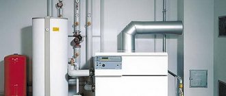
Before you begin designing a heat supply, you need to select the most suitable and economical source of thermal energy - a stove or fireplace, water, steam, air or electric heating.
And we still have to decide on the basic piping diagram for heating a one-story private house, accurately calculate the power and objectively assess the load on the system, taking into account all the features.
An individual heating system must create a comfortable microclimate inside the house in the winter, be economical and reliable in operation
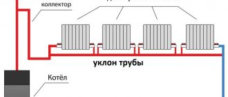
A properly installed heating distribution line makes it possible to organize uniform heating of the air in all rooms of a private house in a minimum amount of time.
EASYMNEMO
Easymnemo is a convenient program for creating two-dimensional diagrams and drawings. Much attention is paid to heat, water, gas supply, and automated process control systems. The resulting drawings can be used for documents, presentations, mnemonic diagrams, advertising materials, business cards. The element library contains images of equipment, graphic symbols from GOST and ABOK standards, etc.
The installation kit contains a catalog of examples (thermal energy, water, gas metering diagrams, heating unit diagrams, boiler equipment connection diagrams, water treatment diagrams, switching diagrams, block diagrams, data transmission diagrams, computer network diagrams, fire alarm diagrams, business cards, etc. .)
Classification of heat supply systems
In one-story buildings, cottages, and houses, autonomous heating systems or those dependent on external power sources are installed. The former operate on liquefied gas, diesel, and solid fuel. The second ones require connection to the electrical network or main gas pipeline.
Another difference between heat supply options is the need for human participation in the operation of the equipment.
Automated systems do not require 24/7 monitoring or manual configuration. Maintaining a comfortable temperature inside the building is ensured by thermostats and temperature sensors.
These devices regularly monitor changes in temperature indicators, which allows the heating system to take into account all factors that directly affect the temperature in the room: solar heat, radiation from household electrical appliances, heating from lighting lamps, etc.
The heat supply system is often installed together with boiler automation. Its main task is to achieve the highest possible efficiency, but not go beyond acceptable parameters.
Automation makes it possible to change the temperature in the house at different times of the day.
When classifying heating systems, the following characteristics are taken into account:
- type of heat carrier - air, water or steam, combined;
- type of fuel used - gas, electric, peat, wood, pellet, coal;
- method of transporting working fluid - with natural and forced circulation;
- the course of movement of the coolant is associated and dead-end;
- method of connecting boiler equipment - single-pipe and two-pipe arrangement;
- wiring diagram - with a vertical or horizontal distribution line, upper or lower, combined.
In multi-apartment buildings, the vertical wiring pattern dominates, while in single-story buildings, a horizontal layout is found. Combined heat supply methods prevail in high-rise new buildings.
User-friendly interface
The Project Studio CS Heating program has a familiar interface, which allows you to minimize the time it takes to implement it. The user works with standard drop-down menus, toolbars, and the command line. In addition, Project Studio CS Heating implements service functions for creating models of heating systems, such as a context menu, tracking and object snapping modes, etc.
Features of coolant circulation
In private low-rise buildings, it is effective to install heating systems with liquid coolant. To do this, the pipes are filled with antifreeze or water.
The movement of the working fluid along the heating circuit can be carried out in natural or forced mode. The water heated by the heat generator enters the distribution pipeline, and then to the radiators. This part of the contour is called the forward stroke.
After entering the batteries, the coolant liquid cools down and is quickly sent to the boiler for heating. This interval is called the return stroke. To speed up the transportation of coolant, a circulation pump is installed inside the system.
Natural fluid movement
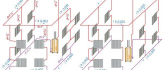
In the heating circuit, horizontal pipelines are sloped, thereby creating conditions for the movement of working fluid under the influence of gravity.
An open expansion tank is also installed - a special tank for receiving excess water to ensure proper and safe operation of all components of the utility network.
Water systems fully work with liquid fuel, solid fuel, gas and electric boilers
Heating systems operate with natural circulation due to the different densities of heated and cold coolant. According to the laws of physics, hot water rushes upward.
In a closed circuit, cold flows inevitably displace heated ones, forcing them to move in the opposite direction from the heat source. A moving fluid with kinetic energy potential passes through all batteries, giving off heat. After returning to the boiler equipment, the cycle repeats.
Today, single-pipe heating systems with water radiators are very popular among consumers. The coolant is water, but it is also possible to use a non-freezing working fluid, which will prevent the destruction of pipes in the winter season
In order for the gravity-flow design to function fully, the boiler is installed below the central axis of the main circuit. Usually the heat generator is mounted in a recess in the floor, but sometimes in basements, with the exception of gas units.
The supply pipeline from the boiler is raised vertically to the highest possible point. This creates additional space in a closed loop for acceleration of the working fluid.
The number of necessary shut-off valves in gravity heating systems is reduced to a minimum. Strict requirements are imposed on the diameter of the installed pipes - it must be at least 32 mm. Since the speed of water movement in the circuit is insignificant, in order to increase the heating efficiency, only large-diameter pipes are installed.
An expansion tank is installed at the top point of open heating systems. In closed ones, as a rule, an automatic air vent is installed
An autonomous heating system, the operating principle of which is based on the natural circulation of the coolant fluid, is the simplest. Such a home heating project is easy to implement in practice. However, this option is only suitable for small private buildings, since the length of the heating circuit is limited to 30 meters.
The main advantage of gravity systems is complete independence from electricity. Read more about heating systems with natural coolant circulation below.
Forced circulation in the system
For private buildings with a total area of more than 60 square meters. m. they design heating with forced transportation of working fluid. A circulation pump is installed in a closed loop to ensure accelerated movement of the hot coolant to the radiators, and the cooled coolant to the heat generator.
Installation of pipes in the system can be carried out without a slope in the horizontal plane. Water moves due to the difference in pressure that occurs in the section of the line between the forward and reverse flow of the liquid.
The presence of a pumping device significantly increases the efficiency of the heating system and minimizes the fuel consumption required to maintain a comfortable room temperature in a private home
A significant drawback of a coercive system is its energy dependence. For constant circulation of water in the circuit, continuous operation of the pump is necessary, and its performance directly depends on the power supply.
In the event of a sudden power outage, the equipment simply will not be able to pump liquid. Therefore, experts recommend additionally installing backup generators that can provide stable, uninterrupted heat supply even in unforeseen situations.
Such schemes can be used when installing heating in buildings of any size. You just need to select a circulation pump with suitable power ratings and provide power supply.
Tips for choosing pipe diameters and connections
A single-pipe heating option can be designed and installed independently, without resorting to complex hydraulic calculations. Let’s simplify the task and give useful recommendations on the design of single-circuit systems:
- The maximum number of heating devices on one loop of a closed Leningradka is 5 pcs. To deliver the required volume of coolant to the batteries, a pipe Ø25 mm (DN20) is sufficient. We make the connections from pipes Ø16 mm.
- If, due to objective reasons, the number of radiators on 1 ring of a closed system needs to be increased, the cross-section of the main line is increased to a diameter of 32 mm (DN25), the liner - to 20 mm. It is not economically feasible to install more than 7 batteries on one pipeline; it is cheaper to lay 2 smaller lines.
- The minimum diameter of a horizontal collector with natural circulation is DN40, outer diameter is Ø48 mm. In a two-story house, the accelerating riser and the beginning of the distribution branches are made from a DN50 pipe (Ø57 mm), remote areas are reduced to a size of DN32. Vertical lines to radiators - DN20-25 depending on the thermal power of the heaters.
- To automatically regulate heat transfer, select full-bore valves with thermal heads. The hole in standard radiator valves is too small.
- Connection to a wall-mounted or floor-standing gas boiler is made according to the standard diagram shown in the picture below. The wiring of an electric water heating apparatus is done in a similar way.
- It is better to connect the Leningradka solid fuel boiler through a three-way mixing valve and a buffer tank. Since there is too little coolant in the system, there is a risk of overheating and boiling. Gravity distribution, holding more than 200 liters of water, can be connected directly to the TT boiler.
Typical connection diagram for a double-circuit wall-mounted boiler with a Leningradka.
The listed recommendations will help you organize heating correctly if you use single-pipe wiring wisely. For an analysis of common mistakes and questions regarding the installation of the Leningradka, see the next video:
Single-pipe heating system
Only one main line is installed in the house, under or above the floor, with batteries connected in series. In such a heating circuit there is no distribution between the supply pipe and the return pipe.
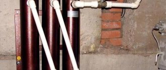
Along the perimeter of a one-story building, only one round pipe with a diameter of at least 32 mm is installed, which is conventionally divided in half. The half leaving the heat generator is called the supply, and the second part of the line is called the return. Radiators/convectors are mounted into the loop using a welded or seamless pipe of small diameter.
Organizing a heating system with natural circulation involves installing a supply pipeline with a slope of 4-5 mm every 2 m
The single-pipe circuit includes the following functional elements:
- heat supply source (boiler);
- heating radiators;
- expansion tank;
- pipe routing elements.
The heated liquid flows alternately into the heating radiators, each time giving off part of its heat. After this, it is already cooled and returned to the boiler for the next heating cycle. Each battery loses heat and the last element in the chain remains the coldest in comparison with the others.
There are several ways to optimize the operation of a single-pipe system. You can additionally install special thermostatic valves for heat exchangers, balancing valves with adjustable hydraulic resistance or compact ball valves. Such equipment helps normalize the heat supply to the batteries.
Installed valves make it possible to regulate the amount of heat entering each individual radiator
Another way is to increase the number of sections of each subsequent radiator in the heating circuit. You can also install a circulation pump. The pumping device is connected at the end of the return line - the place where the working fluid has the lowest temperature.
The single-pipe heating option is easy to install and put into operation. Heat loss is minimized, since absolutely all communications are located inside the living rooms of a private house.
Such a scheme can be organized in the form of a system with horizontal wiring and forced movement of the coolant or a vertical heating network with natural, forced or combined movement of the working fluid.
We also recommend reading our other material, where we examined in detail a single-pipe heating system for a private home.
Horizontal wiring method
Installation of the supply pipe in a horizontal plane is carried out with the required slope in the direction of movement of the heated water. In this case, all batteries around the perimeter of the house must be installed at the same level. To bleed air from radiators, Mayevsky taps or automatic air vent devices are used.
The Mayevsky tap is a special device for removing accumulated air from batteries. The shut-off valve is turned until a hissing sound is clearly audible. When the mixture of gases is removed, water will flow from the tap.
The horizontal line can be installed in the floor structure itself or mounted above it. To avoid heat loss, in the first case it is necessary to insulate the pipes.
Vertical wiring option
In such a system, the transportation of the coolant liquid is ensured by a natural circulation mode, and therefore there is no need to install an additional pump. Energy independence is the main advantage of a single-pipe vertical home heating system.
With this method of wiring, the working fluid, heated to a given temperature, moves up the riser, after which it enters the batteries through distribution pipes. The operating efficiency of a vertically located single-pipe system is achieved by installing the main line at a slope, as well as by installing large-diameter pipes.
Of course, a massive pipeline will not decorate the interior of living rooms. But this obvious drawback can be avoided by installing circulation equipment in the system.
Comparison by installation price
Supporters of single-pipe heating networks like to remind people of the low cost of this type of wiring. The reduction in costs compared to a two-pipe scheme is justified by half the number of pipes. We claim the following: “Leningradka” will cost less than a dead-end system in one case - if you solder the heating from polypropylene.
Let's prove our statement with calculations - let's take as an example a one-story dwelling measuring 10 x 10 m = 100 m² (in plan). Let's put the "Leningrad" layout on the drawing, count the fittings with pipes, then make a similar estimate for the dead-end wiring.
A common return manifold running through the corridor allows the ring line to remain small in diameter. If it is removed, the cross-section of the pipes will increase to Ø25 mm (internal)So, to install one-pipe heating you will need:
- pipe DN20 to the collector (outside Ø25 mm) – 40 m;
- tr. DN25 Ø32 mm for return – 10 m;
- tr. DN10 Ø16 mm for connections – 8 m;
- tee 25 x 25 x 16 (outer size) – 16 pieces;
- tee 25 x 25 x 20 – 1 pc.
Based on the following layout, we will find out the need for pipes and fittings for a two-pipe network:
- tr. DN15 Ø20 mm – 68 meters (mains);
- tr. DN10 Ø16 mm – 22 m (radiator connections);
- tee 20 x 20 x 16 mm – 16 pcs.
Now we will find current prices for plumbing fittings and pipes made of 3 materials: reinforced polypropylene PP-R, metal-plastic PEX-AL-PEX and cross-linked polyethylene PEX from well-known manufacturers. Let's put the calculation results in the table:
As you can see, the costs for polypropylene tees and pipes are almost the same for both schemes - the shoulder scheme turned out to be only 330 rubles more expensive. For other materials, two-pipe wiring definitely wins. The reason lies in the diameters - the prices of larger cross-section pipes increase sharply compared to the “running” sizes of 16 and 20 mm.
You can take cheaper plumbing fixtures from other manufacturers and perform the calculation - the ratio is unlikely to change. Note that we skipped the 90° elbows for pipe turns and other small items, since we do not know the exact quantity. If you carefully calculate all the materials, the cost of the Leningradka will increase even more. An expert demonstrating calculations on video came to similar conclusions:
Two-pipe heating system
The main difference between a two-pipe house heating scheme is the presence of one pipe for supplying water and another for returning it. Moreover, the first one receives hot liquid, while the second one sends the already cooled coolant to the boiler.
Each battery is served by both a supply and a return riser. This makes it possible to regulate the amount of heat received by individual radiators. If we do not take into account the cooling of the coolant in the pipes, it turns out that all heating elements receive liquid at the same temperature.
This is what a standard two-pipe heating system looks like, in which heating of the liquid coolant is provided by a double-circuit gas boiler
The two-pipe heating circuit includes:
- heat generator;
- batteries;
- expansion tank;
- pipes;
- shut-off valves and special devices for air release.
A pipe with hot water runs from the boiler to the expansion tank. Then it is connected to the distribution line in the heating circuit. In addition, an overflow pipe is cut into the tank to promptly drain excess coolant into the sewer system.
Pipes emerge from the bottom of the heat exchangers, combined into one return line. Through it, the cooled coolant returns back to the boiler. The return pipeline is laid strictly parallel to the upper pipes. It must pass through all rooms where the hot water supply line is installed.
Two-pipe forced systems are considered the most efficient for one-story houses and cottages, but they can also provide heat for two-story large buildings.
And these allow you to evenly and very quickly warm up the room and maintain different temperature conditions in the rooms. In addition, dual-circuit design makes it possible to organize not only heating of the house, but also hot water supply.
The circulation pressure in a two-pipe system directly depends on the installation height of the heating elements
Closed heating systems with forced circulation are installed in two versions - with horizontal and vertical wiring.
The first method is implemented in one-story houses with a long pipeline. In such situations, connecting water radiators to a heating circuit with horizontal wiring is the optimal solution.
With the second wiring option, the riser is located vertically, which makes it possible to use the scheme even in multi-story buildings. In such systems, air does not accumulate, since the resulting bubbles instantly rise in a vertical direction, directly into the expansion tank.
Using the built-in boiler pump
This scheme involves the use of boiler equipment with a built-in pump, the power of which is up to 35 kW. It creates a pressure at the outlet of the tank in the range of 20 - 25 kPa, with a water flow of 1000 - 1500 liters per hour.
The installation process is similar to that of a conventional heating element, but an additional pump for underfloor heating is not required.
To fully utilize the potential of the device and create coolant circulation in the heated floor and radiators, it is necessary to correctly connect the device to the circuits.
This can be achieved in this scheme by ring combination - the boiler with the TP, and with the radiator. These two rings are united by a small common area with low hydraulic resistance, thereby one circuit does not affect the other.
In this scheme, the slant filter acts as a slag catcher, and there are air vents in the boiler, radiator and floor circuit.
The essence of the functioning of the ring circuit is that water flows from the container where it is heated into the pipelines. Pressure surges in the supply and return pipes lead to the movement of liquid through the lines and its return back.
Lower and upper wiring diagram
When distributing the system at the bottom, the main line is laid in the basement or basement. It is also possible to install pipes under the floor. The coolant enters the heating equipment from the bottom up.
The mixture of gases is removed through a special air line connected to the risers. In case of unforeseen emergency situations, the return and supply risers are equipped with special shut-off valves.
To implement a scheme with an upper distribution line, the expansion tank is mounted at the highest point of the pipeline. The network is branched in the same place.
It is impossible to design overhead wiring in private houses where there is no attic
Working with floors, rooms and risers
It is possible to download rooms via IFC format. Also, the engineer can independently determine the contours of the room in both automatic and manual modes. You can automatically number rooms if this has not been done previously. And all characteristics and data for all floors and rooms are displayed in one dialog box Building/object model
. Here it is also possible to change the characteristics (properties) of each floor or room - now there is no need to open each drawing separately.
The Interfloor Connections Wizard is used to view and analyze all designed risers in a building and edit their properties.
Types of two-pipe horizontal layout system
The most common option for heating a single-story residential building is a two-pipe heating system with horizontal wiring.
To organize such a heating circuit, the following schemes are used:
- tee or otherwise perimeter;
- collector, otherwise radial.
According to the tee scheme, the pipes are connected by tees, the pipelines are laid around the perimeter of the room, and connected in series to the devices. The coolant in the perimeter system flows from one battery to another, cooling somewhat along the way.
Based on the movement of the heated and cooled coolant, tee options are divided into associated and counter. In a dead-end circuit, hot and cooled water move in different directions. In the associated heated and waste coolant flows in one direction.
In the collector circuit, pipes are led from the central organ of the system, the collector, to each of the radiators, due to which the coolant flows to all devices simultaneously.
The principle of the device resembles the sun's rays emanating from a heat flow distributor usually located in the center. In radial types of wiring, the coolant moves only in different directions.
Design programs
Programs PURMOOZC 3.0., Purmoh30 1.0., PURMOC.O. developed by SANKOMSp.zoo for RettigHeating. The programs contain catalogs of different types of pipes, fittings from various manufacturers and a catalog of steel panel radiators produced by RettigHeating.
Radiator and underfloor heating Purmo CO 3.8 with Pex pipes for 6 and 10 bar.
Program for calculating heat loss. Version 5.0
User manual
To install the program, you need to unpack the setupsdg.exe archive (1.42 MB) and run the installation file.
User manual
To install the program, you need to unpack the setuph3o.zip archive (14.2 MB), run the setuph3o.exe file for installation.
User manual
2D and 3D models of Purmo heating devices for CAD programs
User manual
User manual
Graphic program for designing central and underfloor heating equipment. Version 3.6
User manual
With different parameters of the coolant in Excel.
User manual
www.purmo.com
Rules for drafting a heating system
A well-designed project allows you to launch the most efficient and multifunctional heat supply system.
It must operate smoothly in the climatic conditions characteristic of the specific area where the one-story house is located, and be easy to operate.
Based on the results of the energy audit, calculation of savings and annual heating costs, the optimal option for the home heating system is selected
Drawing up a high-quality project for heating a one-story house and accurately calculating the system parameters are carried out according to a specific plan:
- At the first stage, it is necessary to formulate a technical task taking into account all the requirements and details for the heating system.
- The second step is collecting information on a private property. Specialists must take all the indicators to draw up a diagram of the heating circuit.
- The next stage is the calculation of thermal transfer. To do this, you need to carry out calculations and select the optimal heating scheme that will meet basic building standards and the individual requirements of the customer.
- When all calculations are completed, drawings are made.
- The last stage is the design and delivery of the finished heating system project to the customer.
The main design task is to calculate the correct area of heating equipment and select suitable pipeline diameters. And also determine the performance of pumping devices, calculate the insertion points of valves and system components. Therefore, it is advisable to entrust the process to professionals.
If you really want to carry out the calculations yourself, we recommend reading the material where we used an example to calculate a heating system for a private house.
Determining the power of underfloor heating
If you decide to use a “warm floor” for heating, the equipment should be selected based on the following power indicators:
- for a living room or kitchen, the power is 120-140 W/m²;
- for a glazed balcony – 130-170 W/m²;
- for a bathroom about 150 W/m².
When calculating power, it is important to take into account the floor of the building. For example, for the first floor this figure must be increased by 20%
The calculation of pipes for underfloor heating is carried out according to the following formula: L (pipe length) = AR (housing area)/a (laying pitch) + 2*Lzu (length of heating supply pipes) - 2*Ld (length of heating pipes passing through).
What information do craftsmen need?
Before installation work begins, you should discuss all the nuances with specialists and show your vision of the heating system.
Masters must provide:
- complete information about the materials from which the building’s roof, wall coverings, and window structures are made;
- one-story house plan;
- drawings where the locations of plumbing units are marked.
The service life of a heat supply system is influenced not only by the quality of engineering design and skillful installation, but also by the selected materials, installed boiler equipment, as well as the rational use of heating elements.
Decor
The Project Studio CS Heating program fully complies with the requirements of domestic regulations. All tabular forms comply with GOST 21.602−2011 and GOST 21.110−2013. The placement of the frame with the main inscription on the drawing is carried out in accordance with GOST R 21.1101−2013.
The program implements the following functionality: slope (information is taken from the pipeline), elevation mark (automatically reading the real height of the object), text element (insertion of pipeline designations T1 and T2 into pipes) and a special leader.
UGO table
The program implements automatic generation of a table of UGOs used in the project. The table is generated both for each floor and for the entire project.
The generated table is installed on the active *.dwg file in the CAD workspace.
Lists of drawings, documents and quantities of work
It is possible to receive in a semi-automatic mode a list of working drawings of the main set in accordance with GOST 21.101−2020, a list of reference and attached documents in accordance with GOST 21.101−2020 and a statement of the volume of construction and installation work in accordance with GOST 21.111−84. These statements can be output in Word, Excel or AutoCAD.
Data Consistency
To coordinate data in Project Studio CS Heating, a specialized Project Manager is used. All drawings, specifications and other project documents are guaranteed to refer specifically to the current Project Studio CS Heating project. This allows you to obtain accurate equipment specifications. In addition, the equipment specification always corresponds to the current state of the heating system model.
It is also possible to obtain floor-by-floor equipment specifications. This is especially important in cases where a large facility is being designed and it is necessary to determine what heating equipment needs to be delivered to a specific floor.
The specification template can be customized, which provides a great advantage in obtaining the documentation required by the user.