Here you will learn:
- Operating principle of the collector system
- Advantages and disadvantages of collector heating
- In what cases is a collector heating system acceptable?
- How to choose a distribution manifold
- Principles of drawing up wiring diagrams
- Selection of pipes for the heating system
- Installation of a collector heating system
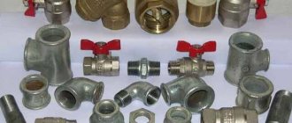
In heating, a collector is an element of water supply fittings designed to distribute through branches, collect and mix coolant from many parallel heat exchange circuits.
The collector circuit ensures the simultaneous supply of coolant to the circuits of underfloor heating and heating radiators (their maximum number in one comb reaches 12) with the same pressure and temperature, which can be set by a thermostat. The collector line differs from single-pipe and two-pipe systems in that it approaches the heating radiators from below.
Operating principle of the collector system
The manifold is a metal comb with leads for connecting pipes and devices. The collector heating system is two-pipe. Hot water is supplied through one comb, and pipes that collect cooled water (return) are connected to the other.
This heating system works as follows. Water from the heating source enters the supply comb (supply distribution manifold), and from there it carries heat through pipes to each radiator and underfloor heating. The cooled water from the radiators flows back into the heating boiler through the return comb (return manifold).
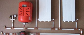
The collector heating system has a closed expansion tank and a circulation pump that moves the coolant. The minimum volume of the expansion tank is equal to at least 10% of the total volume of all heating devices. The pump is installed on any of the pipelines leading to the collectors.
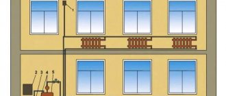
The collectors are installed in special cabinets, which are mounted in wall niches or in a separate room. The collector cabinets should be located at approximately the same distance from each heating device. Pipes can be connected to radiators from above, from the side and from below. The most widespread is the lower pipe connection to radiators. This option provides the best opportunity to hide pipes in the floor. A shut-off valve is installed on each hydraulic circuit coming from the collector, which makes it possible to turn off any radiator without disturbing the operation of the heating system. A valve is installed on each radiator to release accumulated air - a Mayevsky valve, or on the manifold - air release valves. Heat meters and drain valves can also be installed on the collector.
Each hydraulic circuit located after the manifolds is an independent system. This made it possible to create heated floors. These are floors in which pipes are laid in parallel or in the form of spirals, which heat the floor surface. The pipes are laid on a heat-insulating pad, connected to the collector and, after checking the tightness of the pipelines, they are filled with concrete. The height of the screed should not exceed 7 cm. The laying pitch and diameter of the pipes are determined by calculation. The length of one heating spiral should not exceed 90 m. Basically, metal-plastic pipes are used for heated floors, which easily accept any curvature.
When heating a warm floor, the temperature decreases according to the height of the room, and when installing radiators, on the contrary, the higher, the warmer.
Boiler repair
In case of leakage, we repair fire tube boilers in the following sequence:
- We study the documentation and diagrams of the device.
- We search for the problem area and localize it.
- We clean the surface near the crack to bare metal to a width of 15-20 mm.
- We carry out welding work at ambient temperatures above +5C. We use electrodes with a thickness of 2.5 mm or 3 mm. We weld the seam from the side of the drum 2-4 mm larger than from the pipe. The welding direction is from the middle of the crack to the edges using two welding machines simultaneously.
- We clean the seam until it shines and look at its quality. If necessary, we eliminate deficiencies: uncooked areas and shells.
- We test the boiler.
Fire-tube water-heating boilers are used in boiler houses, for heating private households, in industry and other areas.
Sometimes in the construction of fire-tube boilers, due to improper operation, it becomes necessary to replace the damaged section. For these purposes, the gas-flame method is used. In this case, the dimensions of the damaged part must be at least 200 mm or the diameter of the pipe. First, they localize the area, then cut it out with a grinder until the thickness and properties of the metal are preserved, after which they clean and weld a patch made of steel of the same composition.
Fire-tube water heating boilers are used in boiler houses, for heating private households, in industry and other areas. This is due to their high heating efficiency and economical fuel consumption, reliability and ease of operation. The design of fire tube boilers is relatively simple, so they can be easily repaired even independently without the involvement of specialists.
Advantages and disadvantages of collector heating
Collector heating in an apartment or private house has pros and cons. Among the advantages of this system it should be noted:
- Maintainability. If a breakdown is detected, you can easily turn off a separate section of the pipeline without completely interrupting the operation of the system.
- Small cross-section pipes can be used. Since each branch leaving the distributor feeds only one radiator, for its installation it is possible to choose pipes of a small cross-section, and they can be easily placed in the screed.
- Easy to use. Due to the fact that each device has autonomous control, the home owner has the opportunity to set the temperature in any specific room. And if necessary, turn off heating devices in the room. Moreover, the temperature in the remaining rooms will remain the same.
- You can install a collector heating system for a private house with your own hands.
Economic costs are one of the disadvantages of this heating.
In order to create several branches that have different characteristics, for example, different coolant pressures, distribution wiring with a hydraulic compensator is used. A hydraulic arrow is a capacious pipe where several independent branches are connected to the outputs.
The coolant heated by the boiler enters the hydraulic arrow. While circulating, water is taken in at different distances from the taps and passed along the contours.
Due to the fact that heated water reaches the radiators with minimal losses, the efficiency of the system increases. This allows you to reduce the boiler power, saving fuel costs.
The heating system also has disadvantages. The main ones:
- Pipe flow. In contrast to the classical connection, the pipe flow during the arrangement of the collector circuit increases by 2-3 times. The difference in costs is due to the number of premises involved.
- Circulation pumps are required, which will entail additional material investments.
If something happens to the pipes, you will have to open the floor
Another disadvantage is the dependence on electricity: even with the boiler running, the radiators will remain cold during a power outage. Therefore, these systems are not recommended for use in areas where power outages are common.
When laying pipes in a screed, you must not forget that any connection is a possible place for a leak, and if problems occur, you will need to open the floor. And this is quite labor-intensive and costly work. Therefore, the circuit wiring connections are made only above the floor level.
Mixing unit equipment
Listed above are the main components that you will need to assemble the mixing unit yourself. We will describe the completeness in more detail in the table below.
In addition to the above, other parts of pipeline installation can be used to assemble the mixing unit, such as couplings, American ones, and others. They need to be determined at the location where the mixer is installed. Materials need to be used to seal joints.
As a result of the work on assembling mixers, a control panel for the heating system, called a manifold, is obtained.
Heating system manifold for a private house
It can be quite complex or completely simple, located in the basement or in living quarters in specially made manifold cabinets. The main thing is accessibility for maintenance and repair.
Video: how to assemble a mixing unit with your own hands
Knowing from this article how the parts and devices of the mixing unit interact, the developer, even with minimal plumbing skills, will cope with the assembly task. Carefully install one circuit, the rest will roll like clockwork. I wish you success!
In what cases is a collector heating system acceptable?
There is no standard solution when drawing up a diagram of a collector system, and there are also no generally accepted planning standards. The selection of equipment should be carried out by specialists, taking into account the specific tasks that need to be solved.
The opinion of experts should not be ignored: such a system cannot be recommended for heating in multi-storey buildings.
Heating system options in multi-storey buildings
The problem is that heating in the apartment is provided by the supply of coolant to at least two risers. A prerequisite for the system under consideration is the connection of all radiators to one riser.
Having left one source of heat, you will need to shut off the others, i.e. brew them. The entire load will be concentrated on the left riser, and a closed hydraulic circuit will be formed within a particular apartment.
All radiators located on the upper floors will be cut off from the centralized heating system and no coolant will flow into them. Naturally, residents of the upper floors will express dissatisfaction and will demand the forced restoration of the previous communications.
The only legal option for using collector circuits in an apartment building would be when additional valves were installed during the construction process, allowing the connection of circuits of different configurations.
Main manufacturers
Some people pay little attention to this aspect. Confident that the design is simple, they do not think about the fact that over time, water supply collectors fail. Each of them will need repair or replacement. The only question is how soon this will happen, and how often problems will arise. Now there are several “whales” on the plumbing market:
- Far (Italy).
Despite the fact that the products of this company can be classified as a budget segment, the quality is very acceptable. The products are reliable, easy to use, unpretentious, and durable.
- Rehau (Germany).
The price of this product is higher, but the consistent German quality allows you to use the products of this company for a long time. The brass from which the structural elements are made can withstand aggressive environments, does not rust or rot.
- Tiemme (Italy).
The products belong to the middle price segment, which has made them popular among professionals, developers, and contractors. Low cost combined with reliability are the main characteristics of collectors of this brand.
- Luxor (Italian).
The main advantage is the use of innovative technologies in production. Each product is tested for functionality before leaving the assembly line. Material: brass.
- UNI-FITT (Italian).
The company produces a full range of components with which you can install a supply or heating system. The range is constantly expanding, and now there are more than 1000 items.
It's easy to get confused about manufacturers and models. To make the right choice, there are a number of recommendations that guide professionals.
How to choose a distribution manifold
Manufacturers offer a fairly diverse range of collector systems, and craftsmen assemble such a device from improvised means. The choice depends on the location of operation, the cost of the product, the availability of automation, reliability and efficiency.
- The simplest option is a stainless steel pipe to which outlets for connecting radiators are welded. Despite its apparent simplicity, such a distribution comb will cost a considerable amount of money, because for ease of operation it will be necessary to install additional elements.
- A more reliable and inexpensive option is a manifold assembled from polypropylene pipes, connecting tees, necessary valves and stopcocks.
- If full automation in control is required, then it is better to choose a device with the maximum possible set of control elements. Flow meters and temperature sensors will help to evenly distribute the heat flow between radiators and underfloor heating circuits. True, the cost of such a model will be quite high.
In addition to economic factors, the choice of a collector may be influenced by technical operating conditions: maximum system pressure, electrical energy consumption by the device, the number of connected circuits and the potential for adding them. A collector heating system is only possible in modern new buildings, where additional valves are installed in each apartment to connect devices of various configurations.
Installation nuances
The technology for attaching the collector to the wall is quite simple: the TC and radial distribution comb are suspended on mounting brackets, the loops are connected with Eurocone fittings. Pipes going to the top of the collector (usually the “return”) are passed under the bottom.
Advice. No one is forcing you to mount the distributor on brackets. If necessary, the tubes can be spread apart and mounted separately on the wall. The collector box is used in residential areas; when installing the collector in the boiler room, the cabinet is not needed.
Let's briefly list the main points:
- The size of the comb is selected according to the diameter of the pipes used in the heating loops - Ø16 or Ø20 mm. Accordingly, we take a ¾ or 1 inch distributor. The material of the product does not matter; in terms of price/quality ratio, stainless steel wins.
- If the number of comb outlets exceeds 12, assemble a collector assembly of 2 sections. When installing accessories, winding materials are not used, since the parts are equipped with rubber seals.
- A heavier common house collector is suspended on hooks, reinforced brackets, or installed on the floor. Pumps, pipes and other piping elements must not load the distributor with their own weight.
- The hottest coolant receives an indirect heating boiler. The coil and circulation pump of the water heater are connected to the comb directly, usually from the end.
- The radiator heating and TP branches are connected to the manifold through mixing units with three-way valves. A separate pump is installed on each line, selected for pressure and performance.
A heavy coplanar comb can be installed on the floor - weld metal supports
Important point. The mixing unit for heated floors can be installed in the boiler room, near the main comb. Then water at the required temperature will flow to the TP distributor.
Principles of drawing up wiring diagrams
There are no uniform planning standards when drawing up wiring diagrams for a collector system. Equipment is selected for specific tasks.
But experts agree on one authoritative opinion that such a system is in no way suitable for heating apartments. This is due to the complexity of the project due to the fact that two or more risers are usually supplied to the residential premises.
And one of the prerequisites for the implementation of the scheme is the need to connect all batteries to one riser.
You may also find useful information on how to connect a heating radiator.
To implement a collector wiring diagram in an apartment, you will have to leave only one heat channel, having previously welded the rest - it will take on the entire load
If you weld all the other water supply channels so that one riser takes on the entire load, a closed hydraulic circuit is formed within one apartment. All heating devices located higher up the riser will be cut off from the system and will not receive the desired heat.
Residents living above will sooner or later discover the reason for this phenomenon, and the scheme will have to be forcibly redone again, paying a considerable sum.
Manifold heating distribution can be installed in new apartment buildings, provided that additional valves were installed in them during the construction stage to connect circuits of various configurations.
When arranging a collector system, you should take into account a number of key points that are also typical for other types of systems
The collector system is ideally suited for private homes.
The main thing is to adhere to the basic recommendations of professionals when designing the wiring:
- Availability of an air vent. The automated valve is placed directly on the supply and return manifolds.
- Availability of expansion tank. Its volume indicator must be at least 3% relative to the total volume of coolant. But it is also possible to use devices with a larger volume.
- Location of the expansion tank. It is installed on the “return”, placing it in front of the circulation pump along the flow of water. More details about its installation are described in our other article.
- Installation of circulation pumps on each circuit. Their location is unimportant, but due to the low operating temperature they exhibit maximum efficiency on the return line.
If it is necessary to use a comb equipped with a hydraulic compensator, an expansion tank is installed in front of the main pump, which is designed to ensure the movement of water in a small circuit.
By placing an expansion tank in front of the pump, the risk of damage to the device due to water turbulence can be significantly reduced.
The circulation pump is fixed so that the shaft is strictly horizontal. Otherwise, the very first air lock will leave the unit without lubrication and cooling.
If there are additional distribution nodes in the heating system, they should not be communicating.
Circulation pump
Both a single-pipe and a two-pipe heating system for a one-story house with forced circulation cannot do without a circulation pump, due to which the coolant moves in the system. When choosing a pump, you must first consider its power.
The required pump power is calculated using the following formula:
- Q = Qn / 1.163 x Dt,
- Where Q is the pump power,
- Qn is the amount of heat required to warm up the house,
- Dt – temperature difference in the supply and return circuits.
The circulation pump must be located on the return pipe in close proximity to the boiler. During installation, it is necessary to install a heating bypass with three taps and a filter that will prevent the pump from clogging with solid particles in the heating system.
On the market you can find suction pumps that are designed to be installed on a supply pipe. The connection diagram for a heating boiler with forced circulation rarely includes such devices - they are too expensive and in the vast majority of situations do not justify their price tag.
Selection of pipes for the heating system
When creating a manifold wiring diagram for heating a low-rise residential building or other private building, it is necessary to take into account the method of laying pipes throughout the house. If the piping will run under the floor, in a concrete screed, then it is recommended to buy heating pipes in coils so as not to make connections in the floor, as mentioned above.
Plastic pipes must have sufficient flexibility, the pipe material must not be subject to corrosion and the influence of aggressive environments, must not be destroyed at low or too high temperatures, and the service life of the pipes must be extremely high.
The requirements for temperature resistance and tensile strength of pipes are determined by the performance characteristics of the installed heating system in a house or apartment. For individual development, the pressure in the pipes should not exceed 1.5 atm, and the maximum temperature regime should be in the range of 500C -750C. If the house has a “warm floor” system, then the temperature of the coolant in the pipes should not rise above 300C -400C.
Manifold for combined heating
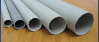
When installing a manifold heating circuit in an apartment building, the pressure in the pipes will always be high, and the pipe material must withstand ≥ 10-15 atm. at a coolant temperature of up to 110-1200C. Therefore, when laying heating pipes in an apartment building, it is recommended to use corrugated pipes made of stainless steel, rather than metal-plastic or PVC products. As a working example, we can cite the Kofulso brand of pipes, which can withstand pressures of more than 15 atm. at coolant temperature ≥ 1100C. The pressure force that causes the destruction of this material is 215 kgf/cm², which is an excellent indicator.
Collector wiring in the apartment
The bending radius of such stainless pipes is equal to their diameter, which allows them to be laid in almost any place and with any bend, without fear that the pipe will leak at the bend. Connections in such piping are made using special fittings, and the twist points are fixed with a lock nut, which ensures the tightness of the connection of corrugated pipes with silicone seals.
But stainless steel is not the cheapest material, and when installing manifold pipes in a two- or three-story building, such a project will be quite expensive. Therefore, it makes sense to use pipes made of cross-linked polyethylene, for example, PE-X brand. These pipes, like other PVC products, are sold in coils, the length of one pipe is 200 meters, the material is able to withstand pressure up to 10 kgf/cm² at a coolant temperature in the system up to 950C. A short-term increase in temperature up to 1100C is allowed.
Corrugated stainless steel pipes
Water pipes made of cross-linked polyethylene are also connected to each other using special fittings in the form of plastic or metal (bronze, brass, copper) fittings with a locking ring, which fits tightly onto the pipe and seals it tightly. The advantage of such pipes is that cross-linked polyethylene has a mechanical memory, that is, assembly is carried out according to the following scheme: the pipe is stretched with a special extender so that a fitting can be inserted, and after some time (up to a minute) the pipe takes on the original diameter and tightly presses the fitting. Additionally, tightness is ensured by a locking ring.
Manufacturing methods
Before you start making a homemade collector, you need to select the material and prepare the necessary equipment. For example, to make a steel model you will need a welding machine. But don’t rush to choose polypropylene. In order to connect polypropylene parts, you will need a special device that is used to weld such pipes. Sometimes it is easier to get an ordinary welding machine than for plastic.
Calculation and distribution of contours
From the very beginning, you need to understand how many heating circuits you will need. It is necessary to take into account each existing heating device, so you will have to evaluate each room according to the list below.
To avoid forgetting anything, use the following list:
- the presence of a “warm floor” system;
- rooms that should have a higher or lower temperature compared to other rooms;
- floor heating;
- heating of each wing.
The rules for manufacturing a heating collector are as follows: the distance between the taps is 10-15 mm, the distance between the supply and return collectors is 25-30 cm.
The diameter of the pipes should be 12.7 mm. The collector itself is made with a diameter of 25.4-38.1 mm, depending on which boiler is installed.
Made from polypropylene
To make a polypropylene manifold assembly with your own hands, you will have to use leftover pipes and fittings.
You will need:
- pipe with a diameter of 32 mm;
- tees 32/32/16 mm.
A tee must be installed on one side. An air vent must be connected to it at the top, and a drain tap at the bottom. On the other side, a valve and pipe are attached. The pipe can be supply or outlet, depending on the purpose of the collector. The supply pipe goes to the boiler.
The remaining outlet with a diameter of 16 mm must be equipped with a valve or flow meter, depending on which collector is for water supply or outlet. At this point the work is completed, and all that remains is to secure the resulting collector systems to the wall using brackets.
Assembly of brass fittings
If a ready-made brass manifold is quite expensive, then you can spend much less money on a homemade one. To build such a structure you will need tees and fittings. They are connected to each other using linen tow or a liquid fixative as a cushioning material. The parts must be connected according to the assembly diagram. An example can be seen in the picture below.
After the collector is assembled, it must be tested. It is difficult to make the connection correctly, so the likelihood of leaks is high.
From a profile pipe
Making a collector from pipes with different cross-sections is the most difficult, since it will require welding work. This model can be called the most “sophisticated”. It is suitable for heating large areas and can have many pipe connections. Often such samples are equipped with a hydraulic arrow.
The following samples will be needed:
- profile pipe 8x8 cm or 10x10 cm;
- round pipe.
The calculation of the pipe cross-section is performed in special programs. It is necessary to set the required heating thermal power, water speed, temperature difference between supply and return.
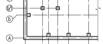
In this case, you will need to build a circuit, taking into account the number of circuits. Remember that the distance between wiring should be about 15 cm, and between collectors - at least 20 cm. A typical diagram looks like this.
Next, you need to mark a pipe with a rectangular cross-section according to the diagram, and then make holes for wiring using a gas cutter. Weld pre-prepared small parts of threaded pipes to the holes. The block is ready, all that remains is to weld the brackets to it, prepare it and paint it.
Installation of a collector heating system
It is advisable to install a collector heating system during the pre-finishing period.
With a horizontal type of heating distribution, a special closed box is installed for the distribution manifold, pump and equipment for adjusting parameters.
It is better to place the collector box in a place where there is no humidity. Usually, a niche in the corridor, a dressing room, a storage room, as well as a specially designated space for communications - a boiler room - are used as the location of the box.
In a building consisting of two floors, collectors with associated equipment are installed on all floors.
Each collector has a certain number of inlet and outlet openings, exactly as many as heating devices - radiators or heated floor coils.
In all rooms, separate branches are laid, combining several heating devices; with this connection, two radiators from the same room for the collector will represent a single heating device.
To organize a heated floor, a collector heating system with wiring in the floor is used. However, not only the installation of heated floors involves laying pipes from below.
Most often, a collector heating system involves placing heating lines under concrete; the height of the screed should vary from 5 cm to 8 cm. Only solid lines are placed in concrete, mostly metal-plastic pipes with a diameter of 1.6 cm. Such pipes are quite flexible, they can be easily lay under concrete.
It is worth remembering that before pouring concrete, a layer of thermal insulation is laid on the pipes and this is done in order to prevent contact between the concrete and the pipes.
A layer of thermal insulation between the lines and concrete will extend the life of the pipes. Sheets of plywood are placed on top of the screed, and the floor covering is already on them.
The lines can be connected to the radiators either from above or from below, that is, the manifold wiring of the heating system can be top or bottom.
Installation of distribution comb
On the floors of houses with horizontal heating distribution, to accommodate the collector, circulation pump and control equipment, you will need to install a closed box - a collector cabinet.
A closed box will protect equipment and shut-off valves from external mechanical influence and give the room a more aesthetic appearance
The manifold cabinet is installed in separate niches of rooms protected from moisture. Most often, a place is allocated for this in the hallway, dressing room or pantry.
When designing the heating of a two-story building, it will be necessary to install two collector groups: on the first and second levels. Additional distribution units will ensure approximately the same length of the circuit.
As an option, you can take as a basis a scheme in which the first group will be responsible for the distribution of heat along individual circuits, and the second will act as a key component in arranging a “warm” floor.
The heated coolant from the room with the boiler flows through the main lines to the collectors installed floor-by-floor
The number of collector inputs and outputs is always equal to the number of heating elements located on the floor: radiators or underfloor heating rings. For each room, a separate branch is laid, which, by combining several heating devices, will implement a passing or dead-end circuit.
To reduce the cost of connecting radiators, a “pass-through” circuit is used.
In a “pass-through” scheme, the thermal valve is installed only on the first circuit of the radiator; due to which the water flow is regulated on all devices connected in series behind it
With a “pass-through” system, several devices connected in series will be perceived as one element.
Subtleties of self-assembly
Before manufacturing the collector, it is necessary to draw up a diagram showing the location of all the elements of the assembly. It is better to choose steel pipes with a square cross-section as the manufacturing material. This type is easy to process, which significantly reduces labor costs for installing pipes.
Manifolds made of profile pipes are used in the heating circuit of objects with a large number of circuits and a hydraulic separator. Square pipe parameters – 80*80 or 100*100 mm
The step-by-step process for producing a prefabricated distribution structure is as follows:
- Marking and cutting of the main body . According to the design diagram, it is necessary to mark the profile pipe. Using a gas cutter, holes are made in the marked areas.
- Preparing connections . The pipes are threaded using a die.
- Staffing . Next, the prepared pipe sections are welded to the body. Their fixation must be done by tack spot welding. Then, during the main welding, the workpieces are welded along the edges.
- Fastening elements . Brackets for fastening are welded to the block.
- Cleaning and finishing . After cleaning, the body is primed and coated with heat-resistant paint for metal products. The supply and return circuits are painted in two different colors for ease of identification.
If polypropylene pipes are used for production, you should pay attention to the presence of a reinforcing layer in them. In its absence, the plastic structure may be subject to deformation due to the current temperature conditions.
For those who do not have special tools, you can assemble a comb from separate ready-made elements. It is better to select components from one company.