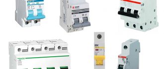
You are faced with the question of choosing a wire (cable). It doesn’t matter what you choose it for, for an apartment, house, garage, cottage or for connecting an electric motor, heating device, compressor, electric lamp or any other electrical device, you still need to calculate the cross-section of the conductor that will be used for connection.
Why is the calculation needed? To put it in simple words, any electrical device (equipment) or room has a current consumption, a load. In order for this wire (cable) to withstand the load consumed by the electricity consumer, a calculation is needed.
Naturally, the calculation is carried out after collecting data about the consumer, that is, it is necessary to calculate the load for each electricity consumer separately and the total load, if required.
But first you need to know how the wire cross-section is determined. The calculation is carried out according to the formula:
S = πD² ⁄ 4 = 0.785 D²
where: S – wire cross-section; π – 3.14; D – wire diameter.
The diameter of the wire can be easily measured using a caliper or micrometer. If the wire core is multi-wire, then you need to measure one wire, make a calculation and multiply by their number. The cross section of the conductor will be obtained.
Wire and cable: general information
It is important to understand the designations when working with wires and cables of any kind. Technical characteristics, internal structure - these are the main differences between the models. It is worth understanding the concepts themselves, which many people are confused about.
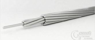
Wire is the name of a conductor that has several components - a thin insulating layer, supplemented by one wire or a whole group of them. In the latter case, the details are simply intertwined.
Cable is another term. They designate one vein, or several at once. Each of them is equipped with its own insulation, but there is also a shell that is common to all contents.
Each type of conductor differs in its methods for determining cross sections, although there are many common features.
Parallel connection of electrical wiring wires
There are hopeless situations when you urgently need to lay wiring, but there is no wire of the required cross-section available. In this case, if there is a wire with a smaller cross-section than necessary, then the wiring can be made from two or more wires, connecting them in parallel. The main thing is that the sum of the sections of each of them is not less than the calculated one.
For example, there are three wires with a cross-section of 2, 3 and 5 mm², but according to calculations, 10 mm² is needed. Connect them all in parallel and the wiring will handle up to 50 amps. Yes, you yourself have repeatedly seen the parallel connection of a large number of thin conductors to transmit large currents. For example, welding uses a current of up to 150 A and in order for the welder to control the electrode, a flexible wire is needed. It is made from hundreds of thin copper wires connected in parallel.
In a car, the battery is also connected to the on-board network using the same flexible stranded wire, since when starting the engine, the starter consumes current from the battery up to 100 A. And when installing and removing the battery, the wires must be taken to the side, that is, the wire must be flexible enough . The method of increasing the cross-section of an electrical wire by connecting several wires of different diameters in parallel can be used only as a last resort. When laying home electrical wiring, it is permissible to connect in parallel only wires of the same cross-section taken from the same reel.
Conductor materials
The material of the conductors largely determines the amount of energy that the conductor as a whole is capable of transmitting. In the production of such products, the following types of bases are most often used:
- Aluminum.
The main advantage is light weight and affordable prices. But there are also negative qualities, including a high electrical resistance of oxidized surfaces; tendency to mechanical damage; low level of electrical conductivity.
- Copper.
The cost of conductors is quite high, but they have become quite popular among consumers. Advantages: easy soldering and welding; high strength, elasticity; contacts with a low level of resistance, electrical, transitional type.
- Aluminum copper.
The cores are made of aluminum and are coated with copper on top. The electrical conductivity of products is lower when compared with analogues made of copper. Other important characteristics include average resistance and lightness while maintaining relatively affordable prices.
In many cases, it is the vein component and the base material that help decide how to determine the cross-section. Parameters such as throughput and current directly depend on this.
What is the deception?
If you don’t know and understand what a 4-square wire looks like or what its diameter is, you can easily be deceived. This deception can come from both the contractor’s electrician and negligent manufacturers. What exactly does it involve?
For example, you entrusted all obligations for selecting wiring for your apartment to a specialist. He must go to the supermarket and use the funds allocated by you to purchase a wire network that meets your requirements and conditions for using electricity. Since you understand absolutely nothing about the sizes, sections, and carrying capacities of wires, you completely rely on the responsible contractor.
In turn, he can conscientiously fulfill your instructions and purchase the cable you need, or he can take advantage of your trust for selfish purposes and buy a cheaper, and, accordingly, lower-grade product. He will simply take the difference and put it in his pocket. The wiring will, of course, be installed. But you will live in peace and not even suspect the threats of the poor quality of your wiring and the fact that you were simply deceived.
Another way to be deceived is to trust the cable industry manufacturers completely and completely. Even despite the fairly high competition, in the conditions of which all suppliers of cable products try to work to the maximum and in no case lose their customers, they often resort to various kinds of tricks. One of the most common such tricks is saving on metal by reducing the conductor diameter. Just think: the manufacturer only needs to reduce the cross-section of a 10-square-meter wire by just a couple of mm2 (what diameter will it correspond to?) in order to break even by significantly reducing the cost of selling hundreds of kilometers of this cable! He feels good, but you may be left with nothing. Or, it would be more correct to say, at the burnt-out wiring. After all, the resistance of the purchased conductor will be much lower than that stated in the markings and documentation.
That is why it is so important to have at least minimal information about what the wires should be like, what the difference is in diameter and cross-section in the cable, and on what basis calculations are made.
We measure the cross-section of wires depending on the diameter
The cross-section of a cable or other types of conductors is determined in several ways. The main thing is to take care of preliminary measurements. To do this, it is recommended to remove the top layer of insulation.
About measuring instruments, description of the process
Calipers and micrometers are the main tools that help in measurements. Most often, preference is given to devices of the mechanical group. But it is also permissible to choose electronic analogues. Their main difference is digital special screens.
Electronic caliper
Vernier calipers are among the tools found in every household. Therefore, it is often chosen when measuring the diameter of wires and cables. This also applies to cases where the network continues to operate - for example, inside an outlet or panel device.
The following formula helps determine the cross-section based on the diameter:
S = (3.14/4)*D2.
D is a letter indicating the diameter of the wire.
If there is more than one core in the structure, then measurements are carried out for each of the component elements separately. After this, the results obtained are added to each other.
Then everything can be calculated using the following formula:
Stotal= S1+ S2+…
Stotal is an indication of the total cross-sectional area.
S1, S2 and so on are the cross sections defined for each of the cores.
It is recommended to measure the parameter at least three times to ensure accurate results. The conductor is turned in different directions every time. The result is an average value that is as close as possible to reality.
A regular ruler can be used if a caliper or micrometer is not at hand. The following manipulations are expected to be performed:
- Complete cleaning of the insulation layer near the core.
- Winding the turns around the pencil, as tightly as possible to each other. The minimum number of such components is 15-17 pieces.
- The winding is measured by its overall length.
- The final value is divided by the number of turns.
The accuracy of the measurement is questionable if the turns do not fit evenly on the pencil, leaving gaps of certain sizes. To ensure higher accuracy, it is recommended to measure the product from different sides. It is difficult to wind thick strands onto regular pencils. It is still better to use calipers.
The cross-sectional area of the wire is calculated using the formula described earlier. This is done after completing the main measurements. You can rely on special tables.
The micrometer is recommended to be used in cases where the composition contains ultra-thin conductors. Otherwise, there is a high probability of mechanical damage.
Table of correspondence of wire diameters and their cross-sectional area
Calculation for stranded wire
Stranded wire (stranded) consists of single-core wires twisted together. Anyone who is even a little familiar with mathematics understands perfectly well that it is necessary to count the number of these wires in a stranded wire. After this, the cross-section of one thin wire is measured and multiplied by their total number. Let's consider the following options.
Calculation using a caliper
The measurement is carried out with a caliper with a conventional scale (or micrometer). Experienced craftsmen always have this tool at hand, but not everyone is a professional electrician.
To do this, using the VVGng cable as an example, cut the thick sheath with a knife and spread the wires in different directions.
Then select one core and strip it with a knife or scissors. Next, measure this core. The size should be 1.8 mm. Please refer to the calculations to prove the measurement is correct.
The resulting figure of 2.54 mm² is the actual cross-section of the core.
Measuring with a pen or pencil
If you don’t have a caliper at hand, you can use improvised methods using a pencil and ruler. First, take the wire to be measured, strip it and wind it around a pencil or pen so that the turns lie close to each other. The more turns, the better. Now let's count the number of wound turns and measure their total length.
For example, we got 10 turns with a total winding length of 18 mm. It is easy to calculate the diameter of one turn; to do this, divide the total length by the number of turns.
As a result of all the calculations made using the formula, you will obtain the required diameter of the core. In this case it is 1.8 mm. Since the diameter of one core is known, it is not difficult to calculate the cross-section of the entire VVGng wire using the already known formula. You can see that the results were equal.
Using tables
How can you find out and measure the cable cross-section if you don’t have a caliper, a ruler, or a micrometer at hand? Instead of racking your brains over complex mathematical formulas, just remember that there are ready-made tables of values for measuring cable cross-section. There are, of course, very complex tables with many parameters, but, in principle, to begin with it is enough to use the simplest of the two columns. The diameter of the conductor is entered in the first column, and the ready-made values of the wire cross-section are given in the second column.
Wiring cross-section table for closed wiring
There is another “approximate” method that does not require measuring the thickness of individual wires. You can simply measure the cross-section (diameter) of the entire thick scroll. This method is usually used by experienced electricians. They can find out the cable cross-section both “by eye” and with the help of tools.
About the cross-section of segment cables
Cable sphere products with a diameter of up to 10 mm2 are almost always produced in a round shape. The conductors are suitable for residential buildings and apartments where household needs are provided. From the electrical network, the input conductors can be made in a segmented version if the cable cross-section increases. In such situations, calculating cable cross-sections becomes more difficult.
Then it is recommended to use the appropriate tables. There are several parameters that take on certain values depending on the cross-sectional area:
- Height.
- Width.
These parameters are first measured on the cables using a regular ruler. After this, it is easy to correlate the data.
Meaning
The choice of a high-quality cable for subsequent installation of electrical wiring is almost the main issue in this entire event. The meaning of its importance lies in the fact that if an incorrectly selected cable is installed, it can quickly burn out, and replacing it will be quite difficult. This is not a socket or a switch that can be easily changed. Moreover, the consequences of a wiring burnout can be very disastrous. Therefore, it is important to reduce all risk to a minimum. And this can be achieved by choosing a cable of the required diameter. Will it be wires with 2-5 cores or will preference be given to a single-core conductor system? You decide for yourself in the process of determining the right wire, based on your specific conditions for consuming electricity in the apartment. But initially you need to be able to navigate exactly the size of the cable cross-section, because safety in the entire house depends on the correct selection of this size.
Current, power and core cross-section: their dependence on each other
It is not enough to determine the cross-sectional area by diameter. It is important to find out what capacity a particular type of product has. The following few criteria will help you make your choice:
- Current load characteristic of a particular cable.
- Power consumed by various devices.
- The strength of the electric current passing through the cable.
About the power
When performing electrical installation work, most attention is paid to throughput. This is especially true for the cable routing itself. The maximum power of energy transmitted through the conductor is determined by the cross-section. It is important to know what total power all devices connected to the wire have.
The labels of most modern devices contain information regarding the average and maximum power calculated by the manufacturer. For example, for washing machines the standard range is from several tens of W/h to 2.7 kW/h. The wire is selected with a cross-section to ensure the transmission of electricity at the highest power level. Connections with two or more conductors require first performing the usual calculations, and then adding the final numbers.
In the case of single-phase networks, the average power for electrical appliances and lighting rarely exceeds 7500 kW. Cable sections are then selected for this value.
It is recommended to round the cross section upward. Indeed, in the future, electricity consumption may increase.
The following recommendations can be cited as an example:
- If the total power is 7.5 kW, the core cross-section is suitable 4 mm2. This product is capable of transmitting up to 8.3 kW.
- In the same situation, the cross-section for a wire with an aluminum core must be at least 6 mm2. Then the throughput reaches 7.9 kW.
In the case of individual residential buildings, it is often typical to use three-phase conductors with a power supply of 380 V. But most of the equipment is not designed for such a voltage. They create a standard level at 220 V through a neutral cable. The current load is distributed evenly across all phases.
Electricity
Lost documentation and labels can cause many device parameters to remain unknown to the owner. Including power. Then you will have to do the calculations yourself, using a special formula.
It looks like this:
P=U*I
U is the applied electrical voltage, with units of measurement – Volts.
I – electric current strength. Measured in amperes.
P – total power, in watts.
Instrumentation can be used if the current strength is initially unknown. We are talking about current clamp meters, multimeters, ammeters.
When the power and current become known, it will not be difficult to find out the required cable cross-section.
Load indicator
Calculation of this parameter is important for users who want to protect themselves from overheating. If the electric current is too large for the cross-section used, the insulating layer is destroyed, even melted.
There is a certain quantitative value called the maximum permissible current load. This is an electric current that can pass through the cable without significant overheating for a long time. To find this value, you first need to find out the power of all electricity consumers. Afterwards the load is determined using the formula:
- I = P∑*Kи/(√3*U)
- I = P∑*Ki/U.
The first option is for three-phase networks, the second – for single-phase.
U is an indicator of the current network voltage.
Ki is a special coefficient, 0.75.
P∑ is the general power level for electrical appliances.
Selecting cable cross-section based on current strength: calculation formula
The amount of current passing through a conductor depends on the length, width, resistivity of the latter and on temperature. When heated, the electric current decreases.
1️⃣ First step. The calculation is carried out in exactly the same way, that is, first the total power of all electrical appliances that can be connected to the network is calculated:
Psum = (P1 + P2 + .. + Pn) × Kс
- P1, P2 .. – power of electrical appliances, W;
- Kc – demand coefficient (probability of simultaneous operation of all devices), default is 1.
2️⃣ Second step. Then the rated current in the circuit is determined:
I = Psum / (U × cos ϕ)
- Psum – total power of electrical appliances;
- U – network voltage;
- cos ϕ – power factor (characterizes power losses), default is 0.92.
3️⃣ Third step. At the last stage, the same tables are used, according to the PUE (Electrical Installation Rules), which are located above.
Cable for connecting the electric motor
What cable is needed to connect the electric motor? This depends on the power of the engine, the voltage of the electrical network in which it operates, as well as the cable laying conditions. This article will show you how to select a cable to connect a 380V electric motor.
Using an example, we will show how to calculate the cable cross-section for connecting an electric motor. Let's say we have an AIR200M2 type engine operating on a 380 V network. The engine power is 37 kW. It is necessary to select an AVBShv cable, which will be laid in a trench along with two other cables located in the same plane (the clear distance between the cables is 100 millimeters), at a depth of 0.7 m, length - 150 m, ground temperature 20°C. The soil is sandy-clayey.
Using the data from the table, we determine the long-term permissible current:
In Table 21 of GOST 31996-2012, in accordance with which the AVBShv cable is manufactured, we find the cable cross-section at which the permissible current load is not lower than Icalc. For a given cable laid in the ground, the minimum permissible cross-section is equal to 16 mm² (Id.t. = 77 A > Icalc. = 70 A).
However, it is still necessary to take into account correction factors that can change the value of Id.t.:
Coefficient k1 depends on the temperature of the environment in which the cable is laid and is equal to 0.96 (at 20°C). Coefficient k2 depends on the resistivity of the earth; for sandy-clayey soil it is equal to 1.05. The coefficient k3 depends on the number of cables laid (we have 3) and the distance between them (we have 100 mm) and in our case is equal to 0.85. Knowing the relevant data, we substitute them into the form and make the calculation:
Since the conditions taking into account additional conditions are not met, we select the following nominal cross-section (25 mm²) and perform calculations for it:
Next, you need to calculate and compare the permissible voltage loss ∆U for the electric motor and for the cable. It is worth noting that the calculated voltage drop for the cable must be less than that of the motor, otherwise it is necessary to use a cable with a larger cross-section. The voltage drop for the motor is 5% (0.05) of the rated voltage at which it operates, that is:
∆U = 380*0.05 = 19 V
Let's calculate ∆U for a cable with a cross section of 25 mm²:
where Icalc is the calculated current,
L – cable length in km,
r0 and x0 – active and inductive reactance, respectively (table),
cosф – engine power factor,
sinф is calculated based on the value of cosф, based on the condition that the sum of the squares of the cosine and sine is equal to one.
Since the previously selected cross-section does not satisfy our conditions, we take a cable with a cross-section of 35 mm² and calculate ∆U for it:
We calculate the voltage loss when starting the engine for a given cable:
The values cosф = 0.3 and sinф = 0.95 are the average values observed when starting the engine. The coefficient kstart = 0.75 is determined by the characteristics of the engine.
The minimum voltage at which the engine can be started is 70% (0.7) of the mains voltage under light starting conditions (duration 0.5-2 seconds) and 80% (0.8) under severe starting conditions (5-10 seconds).
In our case, the launch duration is 10 seconds, so the launch is possible when:
Urest >= 0.8 * 380 = 304 V.
For our cable (section 35 mm²) Uost = 380 - 44.71 ≈ 335 V > 304 V, that is, the condition is met.
Main steps in determining conductor cross-sections
(block diagram)
When choosing the cross-section of cables and wires, you must proceed from the following conditions:
- Determination of the calculated current (power) for connected electrical equipment.
- Permissible voltage loss (voltage drop across connected electrical equipment). At this stage, the cross-section of the conductors is calculated based on the current load and the length of the line. For example, for electric motors at the moment of voltage supply, a voltage drop is allowed that provides the necessary starting torque, and the operation of other electricity consumers should not be disrupted. This is determined by the electrical energy quality standards GOST 13109-97, PUE, as well as in the technical documentation for a specific type of equipment.
- Heating of conductors of a certain type (permissible continuous current). Selection of conductor cross-sections for heating (paragraph of the same name in the PUE). The amount of current in a conductor of a certain cross-section should not exceed a certain value. This parameter depends on the selected type of cable insulation and the location of its installation.
- Mechanical strength of conductor cores for various types of electrical installations. The minimum permissible cross-section of the conductor is established even if the conductor meets all other parameters (defined in the rules for electrical installations).
- Determination of the cross-section of conductors based on economic current density (paragraph of the same name in the PUE). Economically justified conductor cross-section. (In practice, it is mainly used for calculating large objects)
- Checking the reliability of current protection during a short circuit for the selected cross-section and length of conductors (performed at the stage of calculating the protection devices).
(All GOSTs mentioned in the text at the time of writing this article on May 28, 2018 are valid)
Determining diameter using a ruler
The option is probably the simplest. But the accuracy of such measurements leaves much to be desired. Based on the fact that it is almost impossible to determine the diameter of a too thin wire by measuring with a ruler, this method is acceptable for relatively thick wires.
For these purposes, paper or thread is used. The whole point of the measuring process comes down to wrapping a piece of thin paper (or thread) around the wire being measured so that the ends of this piece of paper (or thread) meet. The place where the different ends of the paper come into contact is marked, after which it is removed and measured with a ruler. So, you get the circumference, which you subsequently substitute into the formula and find out the desired value.
D=L/2π,
where: D – diameter, L – circumference, π – constant value equal to 3.14.
Having information about the diameter, you can substitute it into the appropriate formula and find out the cross-sectional area.
Common cross-sections for wiring in an apartment
We talked a lot about names, materials, individual characteristics and even temperature, but we lost sight of life circumstances.
So, if you hire an electrician to conduct wiring in the rooms of your apartment or house, then the following values are usually accepted. For lighting, the wire cross-section is taken at 1.5 mm 2, and for sockets at 2.5 mm 2.
If the wiring is intended for connecting boilers, heaters, stoves, then the cross-section of the wire (cable) is already calculated individually.
conclusions
Before wiring your home, be sure to familiarize yourself with the existing types of wires. Electricians also recommend examining copper wire for color before purchasing, since manufacturers can save on material and use an alloy. This contributes to a significant increase in electrical resistance, which, in turn, does not allow the use of the permissible load level for a particular section.
Experts also advise measuring only the core when making calculations. No matter how thin the insulation on a wire is, no matter how flexible it is, you will have to remove it one way or another to get accurate data. Otherwise, the extra millimeters will give you a reason to use an unacceptably small cross-section of wire for wiring, the load for which will ultimately be excessive. This, in turn, is fraught with consequences.
How to choose a wire to connect the motor
The duration and uninterrupted operation of both the equipment itself and the entire network depends on the exact selection of the cable brand for connecting the electric motor.
Experts recommend choosing a cable for an electric motor, guided by the following rules:
The simplest and most reliable way is to select a cable based on the power of the electric motor. To do this, you should know the reference characteristics of the equipment and the degree of its use under maximum load conditions, adding a certain value to the result obtained, which will allow you to connect additional devices and protect the system from difficult to predict factors.
Domestic and foreign manufacturers offer a fairly wide range of cables for connecting electric motors, but among the most commonly used brands are VVGE, PVVGE, VVGng, KG.
VVGE is a cable with a high degree of mechanical protection, equipped with a copper wire screen secured with braided copper spiral tape. This design determines the predominant use of VVGE cable for connecting electric motors that are sensitive to electromagnetic interference, the source of which is usually a frequency converter.
The insulating shell of PvVGE is made of cross-linked polyethylene, which has excellent thermal and mechanical resistance. Therefore, this brand, regardless of the cable cross-section, is successfully used for connecting various modifications of electric motors installed on both mobile and stationary power plants, incl. receiving power through frequency converters.
VVGng is a product with a shell and insulation made of non-flammable material, self-extinguishing light-heat-resistant PVC plastic compound, which does not support the process of combustion propagation, both during single and joint cable laying.
KG is used when it is necessary to use a cable with increased ductility and bending strength, for example, to connect electric motors located on mobile power units to the power supply network. These can be welding machines, mobile machines, pumps and even cranes.
Source
About tables
Taking into account the fact that traditional conductors for electrical installations act as copper and aluminum strands, tables exist for both types of metal. But, as far as practice is concerned, nowadays virtually no one uses aluminum wires for home wiring. This is due to the fact that aluminum wiring greatly exceeds the risk of a short circuit or fire in the apartment. This is explained by the lightness of such a metal: it has a lower specific gravity. This means that such wires are more quickly and easily susceptible to corrosion and damage, which is why their installation by air is strictly prohibited.
Moreover, you can break it during installation and not even notice it, it is so fragile compared to copper wire. And finally, the main disadvantage of aluminum is its ability to heat up too quickly. This fact, in turn, is fraught with melting of the insulation and short circuit (fire). That is why the use of measuring tables for aluminum wires is practically not in demand.
What is so good about this measuring table:
- Firstly, a clear digital understanding of the indicators specifically for single-core and stranded conductors is given - this greatly simplifies the measurement process.
- Secondly, the table takes into account the conditions of the cable system for both closed and open wiring.
- Thirdly, this method of identifying information is the simplest and most convenient. Taking into account highly developed technologies and the possibility of owning multifunctional gadgets, today everyone can download a table to their smartphone and at the right time see what cross-sectional value the diameter corresponds to. Agree, this is really very practical and convenient: a large amount of technical information is constantly stored at your fingertips. In this case, you do not need to make any mathematical calculations and spend a “lot” of time on it.
Moreover, many conscientious manufacturers, for the convenience of buyers, present their own table, which already contains all the necessary values. All you have to do is determine the planned load for a specific electrical point and think about how the installation should be done. Then you will be able to select the necessary wire yourself, not to mention the fact that you will significantly save on the services of an electrician in this regard.
Determining diameter using a micrometer
Calculating the diameter of a wire is the simplest thing that can be done not only by a novice in installing electrical wiring, but even by a person who has nothing to do with this area. To measure the diameter, simply use one of the most common methods.
The first method is to use a micrometer or caliper. This method is considered the most relevant and often used in practice. This is due to the fact that such devices provide the most accurate measurement indicators. The measurement process itself is carried out by moving the latch to the open position. The micrometer handle must be unscrewed to a distance that will allow the wire to easily fit into the groove between the probes. After this, the handles of the device are activated: they twist the device until the ratchet operates. That's all, you can record the received data.
