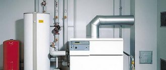
To ensure the safe operation of open-flame gas heaters, electrical circuits in which a thermocouple serves as a temperature sensor are currently usually used.
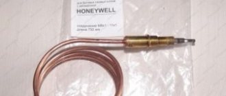
A thermocouple is a junction of two wires made of different conductors (metals). Due to the simplicity of the device, the thermocouple is a very reliable element of the protection circuit and operates reliably in gas appliances for many years. The appearance of a thermocouple with wires for a gas water heater NEVA LUX-5013 is shown in the picture below.
The thermocouple appeared in 1821 thanks to the discovery of the German physicist Thomas Seebeck. He discovered the phenomenon of the appearance of EMF (electromotive force) in a closed circuit when the contact point between two conductors made of different metals is heated.
If a thermocouple is placed in a burning gas flame, then when it is strongly heated, the EMF generated by the thermocouple will be sufficient to open the solenoid valve for gas supply to the burner and igniter. If the gas combustion stops, the thermocouple will quickly cool down, as a result its EMF will decrease, and the current strength will become insufficient to keep the solenoid valve open, the gas supply to the burner and igniter will be shut off.
The photograph shows a typical electrical circuit for protecting a gas water heater. As you can see, it consists of only three elements connected in series: a thermocouple, an electromagnetic valve and a thermal protection relay.
When heated, the thermocouple generates an EMF, which is supplied through a thermal protection relay to the solenoid (a coil of copper wire). The coil creates an electromagnetic field that draws a steel armature into it, which is mechanically connected to the gas supply valve to the burner.
The thermal protection relay is usually installed at the top of the gas water heater next to the umbrella, and it serves to stop the gas supply in case of insufficient draft in the gas outlet channel. If any element of the geyser protection circuit fails, the gas supply to the burner and igniter is stopped.
Depending on the model of the gas water heater, a manual or automatic method of igniting the gas in the igniter is used. When igniting the wick manually, use matches, electric lighters (in older models of geysers) or piezoelectric ignition, activated by pressing a button. By the way, if the piezoelectric ignition stops working, then you can successfully ignite the gas in the igniter using a gas lighter or match.
In gas water heaters with automatic ignition, the gas in the burner ignites without human intervention; just open the hot water tap. To operate the automation, an electronic unit with a battery is installed in the column. This is a disadvantage, since if the battery fails, it will be impossible to ignite the gas in the dispenser.
In order to ignite gas in the igniter using a piezoelectric element, you must turn the knob on the gas column to open the gas supply to the igniter, activate the piezoelectric element to create a spark in the spark gap, and after igniting the gas in the igniter, hold this knob pressed for about 20 seconds until it warms up. thermocouple.
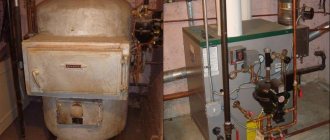
This is very inconvenient, which is why many people, including me, do not extinguish the flame in the igniter for months. As a result, the thermocouple is always exposed to high flame temperatures (in the photo the thermocouple is located to the left of the igniter), which reduces its service life, which is what I had to deal with.
The gas water heater stopped lighting and the igniter went out. A spark from the spark plug ignited the gas in the igniter, but as soon as the gas supply adjustment knob was released, despite the length of time it was held down, the flame went out. Connecting the thermal relay terminals together did not help, which means the problem is the thermocouple or solenoid valve. When I removed the casing from the gas column and moved the central wire of the thermocouple, it fell apart, which is clearly visible in the photo above.
What is a thermocouple?
The thermocouple design includes two dissimilar conductors that are in direct contact with each other at one or more points (in rare cases, they are connected by compensation wires). When a temperature change occurs in the sensor area, voltage is created inside the device.
This ensures temperature control and overheating protection. Thermocouples can also be used to convert thermal energy into other types of energy, including electric current.
The main characteristics of a thermoelectric converter directly depend on the material from which they are made. Any temperature sensor made from two different metals will produce an electrical potential when exposed to temperature, but the response temperature will be different for each combination of metals. Due to this, thermocouples differ in their level of temperature control.
There are many types of thermostats, but their resistance to corrosion will be important. In those models of thermoelectric converters where the temperature sensor is located at a sufficient distance from the measuring device, expansion wiring is used in the design to connect them, thereby reducing the cost of the device.
Most thermocouples are standardized during production to a temperature standard of 0 degrees Celsius. Most manufacturers use electronic cold solder compensation technologies, which correct temperature differences at the device terminals.
Also, due to special electrical engineering, it is possible to minimize the deviation of other characteristics, which makes thermocouples more accurate and measurements as close to reality as possible.
Thermoelectric converters have become widespread in both household and industrial heating equipment. These simple yet useful devices can be found in the design of geyser, kitchen stove, industrial furnace, exhaust gas turbine, diesel engine, etc.
Conclusions and useful video on the topic
How to replace a thermocouple with your own hands:
The operating principle of gas control in the hob and oven:
Thermocouple device for gas stoves:
A gas stove without a properly working thermocouple is a source of danger. If the gas control has stopped functioning, it is quite possible to replace the sensor yourself. There is nothing difficult about dismantling the old and installing a new control device. You just need to purchase a device that matches the existing tile model and work a little with a gas wrench and a screwdriver.
If you have comments on the topic or your own observations on the above information, write them in the block below. We, as well as other readers, will be interested in your stories about the nuances of replacing a thermocouple that you made yourself. Write, don't be shy.
Gas stoves from imported manufacturers have an imperfect “gas control” device, the function of which is to turn off the gas supply in case of accidental loss of flame (flooding, draft, etc.). The device is very capricious and often fails to function.
There are many speculations and “legends” on the Internet. The same fate befell my stove - the oven failed. It will go out, then it will go out. ) I decided to carry out research work on this topic. As the saying goes . a well-studied device is a device broken by your own hands. which is what I did.
I outlined the background to these “research” in this post. Read, try to revive your gas control or “kill” it completely by turning the stove into USSR devices that work just fine without gas control. As a last resort, familiarize yourself with the device.
- User Blog – Stayer
- Login to reply
What is it for?
The thermocouple is used to convert thermal energy into electric current for electromagnetic coils in gas boilers and serves as the main element of gas control protection.
It is made of several types of metal that are resistant to maximum temperatures inside the combustion chamber. The thermocouple works in conjunction with an automatic gas shut-off valve, which shuts off the gas supply to the fuel path.
It is important to know: the protective circuit of gas boilers is designed in such a way that if the thermoelectric element fails or the flame suddenly disappears, the shut-off valves are automatically activated and the gas supply is stopped.
Safety Tips
Due to the fact that the thermocouple is responsible for the safe operation of the gas stove, care should be taken to ensure that optimal conditions are provided during replacement and operation:
- At the first sign of a gas leak, immediately turn off the gas taps and ensure the room is ventilated;
- The direction of the measuring element should be uniformly approaching the flame or located along the heat source;
- The wire should not experience mechanical load or tension, but it should not dangle freely either;
- When replacing one model with another, choose the one that is suitable in terms of parameters and temperature conditions for your stove.
If you are unable to complete this procedure on your own or if you smell gas after replacement, immediately contact your gas service to prevent an emergency.
The design and principle of operation of a thermocouple
Indeed, not every material can be constantly in the open flame zone. The thermoelement is made of metal, or rather, of several metals, so it is not afraid of high temperatures. When operating a gas boiler installation, there is no way to do without it; failure of the thermocouple means a complete shutdown of the unit and immediate repairs. The thing is that the thermoelement works in conjunction with an electromagnetic shut-off valve that closes the entrance to the fuel path. As soon as this part fails, the valve will close, the fuel supply will stop and the burner device will go out.
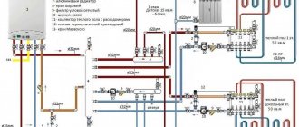
To better understand the principle of operation of a gas boiler thermocouple, it is worth considering the diagram presented in the figure.
Thermocouple circuit
This principle is based on the following physical phenomenon: if you reliably connect 2 dissimilar metals together, and then heat the junction, then a potential difference, that is, voltage, will appear at the cold ends of this junction. And when a measuring device is connected to them, the circuit will close and a direct electric current will arise. The voltage will be very small, but this is quite enough for induction to occur in the sensitive coil of the solenoid valve and it to open, allowing fuel to pass to the igniter.
For reference. Some modern solenoid valves are so sensitive that they remain open until the input voltage drops below 20 mV. The thermocouple in normal operating mode produces a voltage of about 40-50 mV.
Accordingly, the device of a gas boiler thermocouple is based on the described phenomenon, called the Seebeck effect. Two parts made of different metals are firmly connected to each other at one or more points, and the quality of the connection plays a big role. It affects the operating parameters of the element and the durability of its operation. The connection point will be the very working part placed in the open fire zone.
Since many different pairs of metals are used for the manufacture of thermoelements, without going into details, we note that the thermocouple for a gas boiler uses a chromel - aluminum pair. Conductors enclosed in a protective sheath are welded to the cold ends of these metals. The second end of the conductors is inserted into the corresponding socket of the unit automation and secured with a clamping nut.
In the process of igniting the igniter and burner of a gas boiler to supply fuel, we open the solenoid valve manually by pressing its rod. The gas enters the igniter and is ignited, and the thermocouple is located nearby and is heated by its flame. After 10-30 seconds, the button can be released, since the thermoelement has already begun to generate voltage that keeps the valve stem open.
Thermoelectric flame sensor device
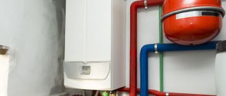
Features of piping a double-circuit gas boiler
The thermocouple is a safety element of a gas boiler that generates voltage when heated and keeps the fuel supply valve open while the pilot light is on. The sensor shown in the photo operates autonomously, without connecting an external power source. The scope of application of thermocouples is gas-using non-volatile installations: ovens, kitchen stoves and water heaters.
Let us explain the principle of operation of a thermocouple for a boiler, based on the Seebeck effect. If you solder or weld the ends of 2 conductors from different metals, then when this point in the circuit is heated, an electromotive force (EMF) is generated. The potential difference depends on the temperature of the junction and the material of the conductors, usually in the range of 20...50 millivolts (on household appliances).
The sensor consists of the following parts (the device is shown in the diagram below):
- a thermoelectrode with a “hot” junction made of two dissimilar alloys, screwed with a nut to the mounting plate next to the boiler pilot burner;
- extension cord - a conductor enclosed inside a copper tube, which simultaneously plays the role of a negative contact;
- positive terminal with a dielectric washer, inserted into the socket of the automatic gas valve and secured with a nut;
- There are types of thermocouples that are connected to automation using conventional screw terminals.
In this model, the heated electrode is attached to the boiler plate without a nut - it is inserted into a special groove.
For the manufacture of electrodes that generate EMF, special metal alloys are used. The most common thermal couples:
- chromel - alumel (type K according to the European classification, designation - THA);
- chromel - copel (type L, abbreviation - THK);
- chromel - constantan (type E, designated THCn).
The principle of operation of a thermal couple made of two different alloys
The use of alloys in the design of thermocouples is due to better current generation. If you make a thermal couple from pure metals, the output voltage will be too low. Most heat generators used in private homes have TCA (chromel - alumel) sensors installed. For more information about the design of thermocouples, watch the video:
Watch this video on YouTube
Differences from temperature sensor
In addition to the thermocouple, a thermal cylinder is connected to the automatic fuel valve of the boiler, which is responsible for turning off the main burner when the set coolant temperature is reached. Externally, the element flasks and copper connecting tubes are somewhat similar. An uninformed homeowner can easily confuse these sensors.
Let us list the main differences between a temperature meter and a thermocouple:
- sensor design - a cylindrical bellows made in the form of a copper flask with a sealed end;
- the thermal cylinder is connected to the gas automatics with a thinner capillary tube than the electricity-generating sensor;
- the heat-sensitive flask itself is installed inside the immersion sleeve or hidden under the casing near the water jacket, and is not attached near the igniter;
- The temperature meter does not detach from the automation at all or the size of the fastening nut differs.
Note. The thermal balloon operates on a different principle: when heated, a special liquid expands inside the flask. The pressure through the capillary is transferred to the automatic valve, which turns off the main burner. The igniter flame does not go out.
Preparation of thermoelectrodes for welding
If the length of the remaining unburned thermoelectrodes allows, a new one is made instead of the destroyed working end.
Table of genera and classes of material.
If it is possible to manufacture a thermocouple from new thermoelectrodes, the compliance of the material of the thermoelectrodes with the thermal converter being manufactured is carefully checked to ensure its quality.
To do this, on the basis of regulatory documents, the type of material, its technical characteristics, and the results of testing the material by the quality control department (technical control department) of the manufacturer are established. If these data meet the technical requirements, the material can be used; otherwise it is subjected to testing.
To check the homogeneity, a piece of thermoelectrode is cut from a coil of material with a length exceeding that required for the manufacture of a thermal converter, after which short copper connecting wires are connected to the ends of the thermoelectrode using clamps. The clamps are lowered into heat-insulating vessels with melting ice (0°C) and the homogeneity of the thermoelectrode material is determined.
To determine the type of material and its class, about 0.5 m of thermoelectrode is cut from the coil and welded with the same piece of “Extra” grade platinum wire. The working end of the resulting thermocouple is placed in a steam thermostat with a temperature of 100°C, and the free ends are taken into heat-insulating vessels with melting ice (0°C) and connected with copper wires to a potentiometer. Based on the thermo-emf developed by the thermocouple, the type and class of the material is determined (Table 1).
In appearance, chromel differs slightly from alumel, but chromel is harder than alumel, which is easily determined by bending, and, in addition, alumel is magnetic, unlike non-magnetic chromel.
The material that meets the technical requirements is cut into pieces of appropriate length and a thermocouple is welded from them.
When cutting, the length of the thermoelectrode should be slightly longer than necessary for placement in the fittings: this is necessary to secure the ends of the thermoelectrodes in the clamps of the thermal converter head.
What metals are thermocouple conductors made of?
All thermocouples are created from certain alloys of noble and base metals that have a constant, repeatable relationship between temperature difference and voltage.
We recommend: Heat Resistant Stove Sealant, High Temperature Chimney Sealant Each group of alloys are used for specific temperature ranges and are used in installed heating appliances.
There are three main types of thermocouples most commonly used in boiler markets:
- Type E. Made from chromel and constant plates. It is highly reliable. Has the factory marking THKn. The operating temperature range is from 0 to +600°C.
- Type J. Similar to the previous thermocouple, but iron is used instead of chromel. The device is practically not inferior in functions to type E, but the price is much lower. Labeling: TFA. The temperature range varies from -100 to +1200°C.
- Type K. The most common and widely used type of thermocouple. Marking: THA. The composition contains plates made of chromel and aluminum. Operating temperatures range from – 200 to +1350°C. Such devices are quite sensitive to the slightest temperature changes, but at the same time they are highly dependent on the environment. For example, carbon dioxide can significantly reduce the life of a device and cause premature repairs.
What does high power consumption mean?
If a comparison of values shows a high power consumption, this indicates that there are short circuits resulting from a violation of the integrity of the wire insulation. In this case, part of the floor will heat up very much, while the other will not work. In this mode, the entire system will not work for a long time, and a lot of electricity will be consumed, which, of course, is uneconomical.
Power of electric mats
This problem can only be solved if it is possible to remove the topcoat. If the cable was laid under a screed, this will not be possible.
What does low power consumption indicate?
If the amount of power consumed is much less than that indicated in the product data sheet, then this indicates an open circuit. In this case, the resistance will be very high, which may lead to cable burnout. You can determine the location of the break if it is possible to remove the entire finishing coating or dismantle a section of it.
Measuring the insulation resistance of a heated floor with a megohmmeter
Action plan:
- you need to disconnect the heated floor from the thermostat and the electrical network;
- The break point is searched using a high-voltage generator and an audio detector. The operating principle of such a device is similar to a metal detector. It passes along the surface of the floor and signals a loss of current - this is the break point; Diagram of the underfloor heating thermostat in the electrical network
- Having identified a break, the coating is dismantled in this place;
- damaged wires are stripped, connected with sleeves and compressed with press pliers;
- the heat-shrinkable sleeve is heated with a hair dryer, and when it cools, it shrinks and becomes a sealant for the restored wire;
- Next, the floor covering is installed.
Advantages and disadvantages
Due to the fact that making a thermocouple is quite simple and inexpensive, it has become an indispensable element of automation and control in gas-using equipment. In addition, there are other advantages of these products:
- Acting as a flame control sensor, the thermoelectric element can also work as a temperature sensor.
- The absence of moving parts, complex components and expensive materials makes the product inexpensive and durable.
- Wide range of measured temperatures.
- Sufficient measurement accuracy to allow the use of this device in heating equipment.
- The simplicity with which the thermocouple is installed or replaced in a gas boiler.
Among the disadvantages of thermoelectric sensors, it can be noted that the increase in the potential difference does not occur in proportion to the increase in temperature, that is, the dependence is nonlinear.
In addition, the voltage increase has a limit and it is small; in the thermocouple of gas boilers its value reaches 50 mV. Such properties of the product do not create problems when interacting with a cut-off device, but when measuring temperature, such a weak and nonlinear signal requires amplification and calibration. The simplicity and reliability of the thermoelectric sensor design also have a negative side. When this element fails, which sometimes happens due to poor quality of the junction, repairing the thermocouple is impossible. The product may simply burn out and there is nothing to repair; all that remains is to replace it, as quickly as possible, since a gas boiler will not work without a thermocouple. But there should not be any special problems here, the device can be easily removed and disconnected, and its price is not at all high.
Advice. Sometimes a thermocouple stops working only because there is a weak contact at the connection point. You need to loosen and unscrew the clamping nut, remove the conductor from the gas valve and very carefully clean its end, and then put everything back together.
Principle of operation
The thermoelectric effect in a thermocouple occurs at the junction of two conductors made of different metals and alloys combined into a current-receiving ring. When the liquidus of the adhesion zones is equal, the potential difference is zero.
As soon as one of the ends is in an area with a higher or lower temperature, a voltage will begin to appear, which will be proportional to the temperature delta. The coefficient of this relationship differs for various alloys.
The operating principle of the gas control system is based on the interconnected functioning of the basic protection elements:
- The user, by pressing, rotating and holding the knob on the working panel of the gas stove, which has a built-in gas control system, opens the gas, which is ignited by the igniter.
- In the burner area, the temperature begins to rise from the combustion products, as a result of which the end of the sensor heats up.
- The thermocouple in the gas stove supplies an electrical signal to the solenoid shut-off valve.
- In stable mode, the valve is in the open position.
- When the flame on the burner goes out unexpectedly, for example, due to spilled liquid, the temperature sensor cools down, the shut-off valve does not receive a signal from it, so the emergency protection is triggered and it closes, cutting off the gas supply to the burner.
After the protection is triggered to turn on the gas stove, it takes a certain amount of time because the sensor does not heat up immediately. In various modifications, the process takes approximately 5 or 20 seconds; before this time, turning on the stove is impossible.
The temperature sensor, as a rule, has a single hot tip located near the fire divider. There are options with 2 or 3 temperature control points. They are used in ovens of various modifications.
Such multi-point sensors have a peculiarity: even if only one of them fails, the shut-off valve will be triggered to close.
Connection and testing
The thermocouple must be connected using electrodes (wires) made of the same material as the thermocouple being connected.
Or metal wires can be used, which have characteristics similar to those of the electrodes on the thermocouple itself.
Before connecting thermocouples for heating boilers, it is important to strip the ends of the wires to remove oxides that affect the accuracy of the measurements. And during installation, it is important to ensure that the fuel outlet and supply pipes are lowered straight down.
If the thermocouple breaks, as a rule, it is no longer possible to restore it, so it is important to know how to check it with a thermocouple multimeter on a gas boiler.
The working thermocouple should operate after 10-30 seconds of heating
To check its functionality, just connect one end to a multimeter - a measuring sensor, and heat the other end using a gas burner or lighter.
A combined electrical measuring instrument, which can be digital and analog, combines several functions (at least the functions of a voltmeter, ohmmeter, ammeter). Multimeter
The working thermocouple should have a voltage around 50 mV.
If a thermocouple malfunction is confirmed, you can replace it yourself.
Checking when a fault occurs
During the operation of the heated floor, deviations from the normal operating mode may occur. Let us consider the main manifestations of system dysfunction.
No heating over the entire floor area
In this case, you need to start checking for a break from the “head”, that is, make sure that power is supplied to the system. If the mains voltage indicator does not light up, you need to check the machine on the panel. After this, you can check whether voltage is supplied to the input of the temperature controller. The presence of voltage at the input and its absence at the output indicates a malfunction in the thermostat itself. The reason may be either in the regulator itself, or in the temperature sensor, which can be checked by measuring its resistance. If you apply voltage to the heated floor directly, without a thermostat, you can test the cable for serviceability.
A situation may arise when the circuit breaker in the panel that supplies the heated floor is turned off by the protection. This indicates a short circuit. To localize the short circuit, we check the resistance between the phase and neutral wires supplying the heated floor. Before ringing the cable, remove the voltage. Disconnect the power wires from the temperature controller. We measure the “phase-zero” resistance in the area from the panel to the thermostat. If the device shows zero resistance, the wiring in this area is damaged; if the resistance is high, we continue the search. Disconnect the underfloor heating cable from the temperature regulator. We take measurements at the regulator input. If a short circuit is detected during the test, then the damage is located inside the thermostat. If not, all that remains is the underfloor heating cable itself. You can check this by measuring the resistance between the cable cores. In this case, you cannot do without opening the floor surface.
What to do when voltage is supplied to the heating elements, but heating does not occur? In this case, the cable must be tested, that is, checked for integrity (or for break, if you like). Having set the multimeter to resistance measurement mode, we take measurements between the cable cores. A resistance value close to infinity indicates a conductor break.
The video below clearly shows how to check an electric heated floor with a multimeter by measuring the resistance of the heating cable:
The heating temperature of the heated floor is not adjustable
If the heating elements over the entire floor area warm up, but the temperature does not change when the setpoint set by the regulator is changed, it is necessary to check the system, determining one of two possible options:
- malfunction in the temperature regulator circuits;
- The temperature sensor is faulty.
In this case, the temperature regulator must be dismantled, disconnecting all wires from it and sent for repair. How to check the temperature controller for a heated floor is shown in the video:
If you suspect a sensor, you should check its resistance. To do this, the sensor wires are disconnected from the regulator and the resistance between them is measured. A conclusion about the serviceability of the heated floor temperature sensor can be made by checking the value of its electrical resistance and comparing it with the passport data. As a last resort, you can do without a multimeter. Since this element cannot be repaired anyway, you can proceed as follows. Buy a known-good sensor, place it on the heated floor, and connect it to the regulator. If you ensure good contact of the sensor with the floor, the system should work if the regulator is working. After this, you can install the new sensor in place. This will require opening up the floor surface.
How to remove a thermocouple from a gas water heater
In order to be able to quickly repair a geyser with my own hands and always have warm water, taking into account the experience of long-term operation of gas water heaters of different models, I always have a set of spare parts on hand. Rubber gaskets, tubes, thermal relay and thermocouple included. Therefore, within half an hour the thermocouple was replaced with a new one, and the column again began to properly heat the water.
The thermocouple is secured to the left on the common bar with the igniter and spark plugs using a nut. Before unscrewing the nut, you need to slightly unscrew the left self-tapping screw holding the bar so that it does not interfere with the wrench turning.
Next, use an open-end wrench to unscrew the nut by rotating counterclockwise until it completely comes off the thread on the thermocouple body. After this, the thermocouple will easily come down from the bar.
In the next step, you need to use an open-end wrench to unscrew the contact screw from the gas-water regulating unit. The screw is located on the opposite side of the gas control knob.
All that remains is to remove two terminals from the thermal protection relay, and the thermocouple, complete with wires, will be removed from the gas water heater.
Installation of a new thermocouple is carried out in the reverse order, and it is desirable that the current-carrying wires do not touch either the internal metal parts of the gas column or the casing after its installation.
Comments
I especially liked “try to revive your gas control or “kill” it completely by turning the stove into a USSR device that works just fine without gas control”
- Login to reply
Either no one is reading this, or one of two things. Interesting article. It's a pity, it's hard to read... The font is small and blurry. And in the pictures the text (in the explanatory frames) is completely unreadable. Apparently the material was ripped off from somewhere and copied poorly. I'd like to see the original.
- Login to reply
reset your @ . I'll send it to you by email. article. if there is the same effect, I will correct it, I am the “aftar” of this creation. I don't do plagiarism. ). poked around personally..
- Login to reply
It is not clear why the quality was lost. The original Word document looks flawless.
- Login to reply
- Login to reply
Good afternoon. I wanted to get an opinion or get advice from experts. The valve “stopped” working: I checked the thermocouple separately - it produces 40 mV from a regular burner; I checked the valve - it works exactly starting from 700 mV (dead AAA battery). I don’t understand what the problem is yet, because... It seems like the emf of the thermocouple is within normal limits (I’m very surprised by the reading of your thermocouple. Maybe there’s a problem there.). Because the valve operates from external power, I wanted to know whether the winding on the valve will not be covered when used in this way?
- Login to reply
Good afternoon, I don’t know the indicators of the thermocouple, because... it failed, but the valve was triggered somewhere around 1V, “pulled” 400mA. My entire “kitchen” in the post, when powered by an external power supply, is relevant as a temporary solution to the problem during the period of purchasing (purchasing) a valve or thermocouple, or a kit in general. If you don’t think about buying them, unscrew the valve, remove the rubber gasket, remove the spring - the headache will disappear. ) The stove will turn into the USSR - a device. )Good luck.
- Login to reply
PS. Try repairing the contact connections by removing the thermocouple, cleaning the seat, etc. connections between the terminal and the housing. It seems to me that your thermocouple is bad. Don’t worry about the valve winding. Increase the voltage until the valve operates - it will not take extra current.
- Login to reply
Thank you for such a quick response! I have already cleaned the thermocouple contacts as much as possible, but, alas, or fortunately, there was nothing to clean there except carbon deposits. I have already taken measurements on a test bench without unnecessary details. Considering the gluttony of the valve, it also seems to me that the problem is in the thermocouple, but in contrast to this there is a table of TEDS of standard thermocouples (https://kipiya.ru/2008/04/04/tablica-termo-eds-standartnyx-termopar/, https:/ /temperatures.ru/pages/graduirovochnye_tablicy), where the maximum readings do not exceed 70 mV. That is why I began to look for help, because at the moment I have two impressions: the valve winding has deteriorated since it requires so much to hold and the thermocouple has deteriorated since it produces so little. But neither of these stand up to criticism. Or am I missing something. In general, there are two options left: either remove the valve or buy a kit. For now, I’ll just bypass the thermocouple using external power.
- Login to reply
in terms of standards - the table focuses on industrial thermocouples, low-current (USSR-CIS standards), as for gas control - these thermocouples are “tailored” for bourgeois stoves. In fact, industrial thermocouples produce a LOW-CURRENT SIGNAL to electronic devices (with further amplification thereof) for control thermal processes. As for the t/p gas control, it (it was specially developed for the valve) produces a significant current to the valve, and the valve needs to overcome the resistance of the spring and also press down the gasket. In production there are hardening transformers (soldering of cutters). They produce 2 volts from the step-down winding between the contacts. The cutter is clamped and heated. The current is 400 - 600A. Approximately the gas control thermocouple is rated for a current of up to 500mA. Gas control cuts off the gas from the oven faucets, burners... It won’t go anywhere else until you open the faucet. If you look at the comments on the Internet about gas control, you can conclude that it is not perfect and is short-lived. = flush cistern with electronics unit. ) They install it to “make money” (IMHO). and there are no spare parts. There is a place for do-it-yourselfers to practice.
How to weld a burnt thermocouple of a geyser
Due to professional needs, I periodically have to manufacture thermocouples for devices for maintaining a given temperature in drying cabinets and in equipment for annealing twisted magnetic cores for transformers at a temperature of 800°C. Therefore, when manufacturing the next thermocouple, I decided to try to restore the functionality of a burnt thermocouple from a gas water heater by welding.
The central wire of the thermocouple was welded to the copper wire of the electrical wiring and had a length of about 5 cm. In the photograph, the soldering site is clearly visible on the left. This length of wire would be enough for several repairs.
The tubular conductor of the thermocouple, about a centimeter long, was completely burnt out, but a part of it with a thicker wall remained.
The previous welding site was removed from the central conductor, and the thermocouple parts were cleaned of soot and deposits using fine sandpaper.
The central conductor was inserted into the base of the thermocouple so that its end protruded one millimeter. Welding was carried out on a special installation, the device and circuit of which I will describe below, for about four seconds at a voltage of 80 V and a current of about 5 A.
We recommend: Do-it-yourself potbelly stove drawings (The most effective) photo + video
I did not make a video recording of the thermocouple welding process for fear of damaging the camera from a bright arc, but I took a photo of hot graphite powder a couple of seconds after the welding was completed.
The thermocouple junction turned out, contrary to my expectations, of excellent quality and beautiful shape. I became confident that I had not started repairing the thermocouple in vain.
To prevent the central conductor of the thermocouple from shorting to its body, fiberglass wool was tightly packed into the gap. Asbestos is also good for these purposes.
To ensure that the thermocouple was working, it was heated with a soldering iron to a temperature of about 140°C.
The multimeter recorded the EMF generated by the thermocouple as 5.95 mV, which confirmed the serviceability of the thermocouple. It remains to check the functionality of the thermocouple in the gas column.
Although the thermocouple became a centimeter shorter, its length was still quite enough for the junction to be in the igniter flame. The restored thermocouple has been working flawlessly in the gas water heater for several months now, and, I believe, will work much longer than a factory-made thermocouple, since the junction point has become much more massive.
Cleaning
If the sensor stops sending a signal to the shut-off valve, you should not change it immediately; you need to check the thermocouple and may have to clean it.
The specific symptom of such a failure can be determined by the following actions:
- press the igniter button;
- the burner lights;
- the torch burns until the finger rests on the button;
- As soon as the hand is removed from the button, the flame disappears.
This is a sign of a dirty thermocouple. The end of the temperature sensor is placed right next to the burner and flame. In the oven it is also close to the flame divider at the top of the chamber. This part of the thermocouple must be free of carbon deposits, deposits and any defects.
When the working area of the temperature sensor is covered with carbon deposits, it is cleaned with sandpaper. The larger the carbon layer, the less thermal energy is supplied to the sensor and the less emf is created.
The millivolts generated are probably not enough to operate the shut-off valve. If this action does not help, you need to check the functionality of the thermocouple.
Installation device for thermocouple welding
Attention! When repeating and operating the proposed installation for welding thermocouples, due to the lack of galvanic isolation of contacts for connecting a thermocouple, it is necessary to observe the polarity of connecting the installation to the electrical wiring. Only the neutral wire must be connected to the thermocouple. Touching a phase wire may result in electric shock.
There are several ways to weld thermocouples: in an electric arc, in a salt electric welding machine, using an acetylene torch and in graphite or carbon powder. I weld thermocouples to measure temperature using LATR and a ceramic container filled with graphite powder. The technology is simple, does not require special equipment or experience and is accessible to any home craftsman.
I inherited a homemade installation for welding thermocouples, shown in the photo. The installation is a metal box in which an LATR, an alternating voltage voltmeter and a ceramic glass for graphite powder are installed.
The electrical diagram of the installation is presented above. The supply voltage is supplied through an electrical plug from household electrical wiring through a switch and fuse for a current of 5 A to the primary winding of a laboratory autotransformer. The neon lamp HL1 serves to indicate the switched on state of the installation. Resistor R1 limits the current through HL1.
At the bottom of the ceramic bowl filled with graphite powder, there is a copper plate to supply current, to which supply voltage is supplied through a brass screw from the alternating contact of the LATR. The neutral wire coming from the power plug is connected to the common wire of the LATR and to the thermocouple being welded using an alligator clip.
The amount of welding current depends on the voltage. For this purpose, the installation has an alternating voltage voltmeter, indicated in the diagram by the letter V. The voltage value is set by rotating the LATR knob and is selected experimentally depending on the diameter of the wires being welded and lies in the range of 20-90 V. There are no special elements in the circuit that limit the amount of current. It is limited by the cross-section of the circuit wires and the resistance value of the graphite powder.
The photo shows the front panel of the thermocouple welding installation from the back side. As you can see, the LATR is fixed directly to the bottom of the box, and all other elements of the electrical circuit are fixed directly to the panel.
To weld a thermocouple on the installation, it is enough to twist the conductors, clamp them with a crocodile and smoothly touch the graphite surface. An electric arc will occur, releasing a large amount of thermal energy at one point. The conductors begin to melt, and the molten metals, mixed with each other, form a neat ball, as in the photograph, due to the forces of surface tension in the liquids.
Welding time usually does not exceed three seconds. The burning of the arc is accompanied by a characteristic hissing sound, with a decreasing frequency over time. If you have experience, you can easily determine the end of the welding process by sound. Due to the large mass of the thermocouple for the gas water heater, it took about five seconds to weld it.
Here is a photo of a chromel-alumel thermocouple made of ∅0.5 mm wires, the welding of which is demonstrated in the video above. As you can see, a neat round junction has formed at the place where the wires were welded. This thermocouple will last a long time.
On a thermocouple welding machine, I mainly have to weld chromel-copel (TCA, Type L) and chromel-alumel (TCA, Type K) thermocouples with a conductor diameter of 0.2-0.5 mm. It happened during repairs that even a K-type thermocouple with a conductor diameter of 3 mm was welded. Copper and aluminum wires with a diameter of up to 2.5 mm are well welded together. But when installing electrical wiring, it is difficult to use the installation for welding connections due to its overall dimensions.
To protect the eyes from bright light when visually monitoring the welding process, it is inconvenient to use glasses or a welder’s protective mask, so I use a high-density neutral density filter from the camera.
As practice has shown, with the help of a simple installation, which is an LATR and a ceramic bowl with graphite powder, you can successfully repair thermocouples used in gas water heater automation systems at home with your own hands.
Types of temperature sensors for gas
Thermocouples of gas stoves differ in the alloy of conductors and the type of connection to the valve. And the main thing here is that each manufacturer of gas-powered equipment uses its own versions of electromagnets with different connection connectors.
In most cases, it is impossible to move the thermocouple gas control sensor from one tile to another.
The thermocouple must correspond to the model of the gas stove; installing a “left” control device is prohibited for safety reasons
The following alloys and metals are used to create thermocouples:
- constantan + chromel;
- copper + constantan;
- copper+copel;
- nisil + nichrosil;
- alumel+chromel;
- constantan+iron;
- chromel+copel;
- platinum+platinum;
- tungsten+rhenium.
The accuracy of the device and its operating temperature range depend on the alloys used. For example, a chromel-alumel thermocouple is designed to operate at 0–1100 0C, an iron-constant thermocouple at 0–700 0C, and a platinum-platinum-rhodium thermocouple can withstand heating up to +1700 0C.
Household gas stoves usually use thermocouple sensors made of alumel and chromel or constantan and iron. They are inexpensive and quite suitable for the temperature conditions of a gas cooktop.
Checking the thermocouple of a home geyser
Long-term operation of a home geyser fully allows for such a moment when the thermocouple fails. In this case, it is necessary to check the functioning of the system and, accordingly, check the control sensor itself.
Of course, not all owners of gas equipment are able to perform such work. And from a safety point of view, the best solution would be to contact the gas company to solve this problem.
But at the same time, situations may be different, including the impossibility of contacting specialists for some reason. Then the only option left is to try to do the work yourself.
The picture shows one of the options for an installed thermocouple that needs to be checked: 1 – the directly hot area of the sensor, which is most often susceptible to destruction; 2 – fastening nut, which must be unscrewed for dismantling; The same nut can be used on the other end of the thermocouple
In this scenario, a user inexperienced in gas matters is interested in how to check the thermocouple on a gas boiler using a tester - a common electrical and electronics diagnostic device. Let's try to reveal this technological point in order to make the task easier.
We recommend: Geothermal heating: what is it, the principle of operation of the system and options for a private home using the heat of the earth, reviews from owners
Stage #1 - preparation for testing by a tester
To begin with, let us remind you that a tester is a measuring device - pointer or digital, with which it is possible to measure:
- resistance;
- voltage value (AC and DC);
- current strength (AC, DC).
The measured values marked are sort of basic. Moreover, modern testers are able to check a number of other parameters, for example, inductance or capacitance.
But taking into account the principle of operation of the thermocouple of a household gas boiler, the voltage measurement mode in the millivolt range is quite sufficient.
The procedure for testing a thermocouple using a measuring device and a simple heating element - a paraffin candle. As can be seen from the tester readings (25 mV), the gas burner flame control sensor is working properly
In addition to the measuring instrument (tester), the installer will need another fairly simple tool - a heating source. It is better if such a source has the ability to emit an open flame. Therefore, the best option here would be to use a regular paraffin candle.
Stage #2 - visual inspection for defects
The procedure for testing the flame control sensor is simple. However, before proceeding with the hot test, it is recommended to carefully examine the thermocouple visually from the outside.
When inspecting the area of the junction and the descending rod, physical defects of the metal, including burnout areas, should not be visible on the surface.
Stage #3 - testing the sensor's performance
After completing the visual inspection, you can proceed directly to the hot test. To do this, the junction area and the downward section of the gas column thermocouple rod are placed above the candle wick.
Next, a measuring device (tester) is connected to the terminal ends of the thermocouple, after which the candle is lit. The generated potential is observed on the working scale of the measuring device.
In fact, to check the functionality of the sensor, it is permissible to use any suitable heating source, for example, a household lighter. True, depending on the power of the heating source, the readings on the tester may be below normal or, conversely, above normal
The absence of any electrical potential readings clearly indicates a sensor malfunction. In case of partial defects, chaotic (unstable) readings of units of millivolts may be observed on the measuring device. If the geyser sensor is working properly, a stable value equal to tens of millivolts (20-30 mV) is usually recorded on the device.
Moreover, as the thermocouple body is heated by a candle flame, the readings on the instrument scale change slightly upward. If the candle flame is extinguished, the tester readings will tend to zero as the rod body and junction area cools. That's all. With this development of events, the thermocouple, as being in good working order, can be safely placed at the site of action.
Best models
When deciding on a specific model of outdoor thermometer for measuring air temperature, a number of important points should be taken into account. For example, bimetallic devices have the shortest service life. Alcohol thermometers last a little longer, but over time they begin to “lie” due to alcohol evaporation. In terms of accuracy of readings, miniature electronic weather stations are the leaders.
One of the most common alcohol devices is the “Standard” TB-202 window thermometer, which has the following characteristics:
- thermometric liquid – methylcarbitol;
- measurement range – from -50 to +50 degrees;
- scale division price – 1 degree;
- thermometer weight – 30 g;
- dimensions (length, width, height) – 205x60x25 mm;
- accuracy – ± 1 degree.
For maximum convenience, the device holder is rotatable. This feature allows you to install the thermometer on any side of the window.
During installation and further operation of TB-202, the following rules must be observed:
- prevent mechanical damage to the device;
- install a thermometer on the part of the window that opens less often;
- Place the thermometer in places protected from direct sunlight as much as possible.
In accordance with reviews and current statistics, the famous “Bee” is now enjoying record popularity. We are talking about the Garden Show window thermometer, which is attached to the glass using silicone suction cups.
The device measures temperature in the range from -40 to +50 degrees. One of its main features is the absence of mercury.
The bimetallic model TFA-146006 represents the optimal ratio between the price of a measuring device and its quality. The device is attached to almost any flat surface using the Velcro included in the package. Measurement range from -50 to +50 degrees with an error of 1-2 degrees. The diameter of the thermometer is only 72 mm.
Its main advantages include:
- accuracy;
- quality of German production;
- affordable price.
The electronic outdoor thermometer RST 01077 is characterized by increased measurement accuracy. Unlike its “classmates,” this model cannot boast of having an arsenal of additional functions. However, this is fully compensated by its performance qualities.
The thermometer operates in the range from -30 to +70 degrees, and all results are displayed on the device screen.
Another device worthy of special attention is the digital thermometer-moisture meter AR807. Due to its versatility and functionality, this device is widely used in construction, agriculture and many other areas. One of its key characteristics is the maximum measurement accuracy (the error does not exceed one degree when determining temperature and 5% humidity).
This model operates in the range from -40 to +70 degrees and 20-99 percent. Temperature readings are recorded every 2 seconds. In this case, all data is displayed on a high-quality display. The device is equipped with integrated sensors and also has clock, alarm and calendar functions. Its main disadvantages include the rather high cost, exceeding 1 thousand rubles.
Possible malfunctions and methods for eliminating them
If, when you press the gas supply button, the burner turns on and immediately goes out, this indicates a malfunction of the thermocouple. It may also be the result of poor contact between the converter and the solenoid valve.
Repairing a gas boiler thermocouple malfunction is as follows:
- remove the end of the thermocouple by unscrewing the clamping nut with a wrench, with which the transducer is attached to the valve;
- if upon inspection the presence of contaminants or oxides is detected, clean the contact area with fine sandpaper;
- Next, use a multimeter to check the functionality of the device.
If, when checking, the sensor shows a voltage of 50 mV, you can try to start the boiler. If the problem persists and the burner goes out, this may indicate a faulty solenoid valve.
If the valve is in working condition, it is necessary to ensure the correct connection of the converter to the valve: find the appropriate position of the clamping nut for optimal contact.
You should know that if the gas boiler converter fails, the device cannot be restored. Here it is necessary to replace the thermocouple by installing a new sample in its place. Products in this category are offered by many domestic and foreign manufacturers, including Arbat, Zhukovsky AOGV plant, Honeywell concern and other industrial companies. The price range for this device varies between 600-2000 rubles.
The main areas of application of thermocouples are automation of gas equipment, foundry industry installations and many other areas of production. Based on this device, a whole range of thermostats and thermometers for household and industrial use has been developed. In the hands of folk craftsmen, a thermoelectric converter can become the basis for a mini power station; it is used to create chargers with which you can charge low-power devices from an open fire, including from a fire.
Options for faults in picture tubes
If, when you first turn it on, the image is distorted or ripples and stripes are observed, then the posistor is most likely to blame. How to check an element in a circuit with a multimeter? It is easier to do this on a cold circuit, because the resistance of the posistor is minimal.
Often the soldered contacts simply fall off due to prolonged use. A posistor refers to circuit elements that constantly operate in a heated state. Using an ohmmeter, check the connection of the screen mask with the output of the second leg of the posistor. If it is minimal, this indicates a reliable connection. Perhaps the element does not trigger the cutoff.
Read also: What current to charge AA batteries
If the posistor is faulty and short-circuited, then the power supply fuse blows when turned on for the first time. Provided that this occurs without a visible short circuit in the circuit, you can check the malfunction by completely disconnecting the screen mask and the posistor.
How and in what cases can it be restored?
The thermocouple is designed in such a way that any damage or contamination can reduce the voltage it produces below a critical level. A very common cause of malfunction is carbon deposits or a layer of soot on its working (heated) part. To restore the thermocouple, just clean it with a soft brush or cotton wool and alcohol, while avoiding scratches and other damage. After cleaning, it is worth checking the voltage again following the instructions above.
Oxidized contacts are also a common cause; they can be carefully treated with sandpaper. If the thermocouple has a deep black dent or hole due to burning, it is guaranteed to need to be replaced.
Required tools and materials
If you decide to make a thermometer yourself, then you should prepare all the necessary materials and tools. Thermometers can be made in different ways and from different materials - both cheap and affordable, and expensive. Let's look at what you might need to create such a useful item:
- ruler;
- marker with a thin rod;
- a regular store-bought thermometer (will be needed to calibrate a homemade product);
- plastic bottle (if the thermometer is made from it);
- thin glass or plastic tube;
- scotch;
- a special board (if you plan to manufacture a more complex electronic thermometer);
- light cardboard or half-cardboard (you can also make a thermometer from it);
- thick white or red threads;
- needle with a large eye;
- pencil.
It is advisable to prepare all the necessary components in advance before starting all work, so that at the right time you do not have to look for the necessary device (especially if it is small) throughout the house, wasting time.
Rate this article:
How to replace a temperature sensor?
Most options for repairing (replacing) the thermocouple of a household geyser require dismantling this element from the equipment structure. Accordingly, a potential technician needs to be aware of how to remove and install the sensor. Let's look at how to replace a thermocouple in a gas boiler and what is needed for this.
The tool set is quite simple. Usually one or two open-end wrenches are required for a 14 (or 15) nut.
It is worth noting that, based on the specific boiler model, the size of the fastening nuts may differ, as well as the design of the thermocouple itself. On some models, the thermocouple is secured with screws.
Dismantling the control sensor on the gas water heater for subsequent performance testing. Depending on the boiler model, sensor mounting options may vary
Thus, the technician needs to free the sensor from the mounting screws, after which the structure is removed and can be repaired or replaced with a new one. Installation of the new element is carried out in the reverse order.
Are you having problems with your geyser thermocouple? In this case, we recommend that you read the repair and replacement manual.