Creating a brick house project is a very important step on the path to building your own home. Brick house designs determine the speed of construction, as well as the cost of future capital investments. The plan of a private house, indicating all the required dimensions, allows the customer to imagine what the finished home will look like, and is also an indispensable link in construction, thanks to which any issues can be resolved, including with supervisory authorities.
Project of a two-story brick house with a garage
The most popular projects in private construction are projects of a two-story brick house and a house with an attic. Such houses allow you to save space on a plot of land, and are also built cheaper by reducing the cost of building materials.
In addition, thanks to the construction of houses with an attic, it is possible to reduce the cost of building foundations by reducing the weight of the structure. Considering that laying foundations in some cases can account for about forty percent of all construction costs, the savings are quite significant.
Advantages of a two-story brick house
The diversity in the construction markets is amazing with the huge number of different building materials, which expand the capabilities of both developers and designers. The most popular building material, whatever one may say, is brick.
Project option for a large brick two-story house with a garage
The ability of brick to breathe allows you to build houses with an ideal microclimate for living. There is no need to talk about the reliability of brick blocks and the quality of future buildings: everything is at the highest level. Brick has proven itself well as a material for building houses. It can be used to build any building - from low-rise houses to multi-storey buildings. Brick is considered a fireproof material, so if you plan to install a fireplace in your house, there should be no obstacles to this.
The only thing that needs to be noted in terms of the disadvantages of brick houses is the high labor costs for construction and the long construction time compared to other building materials.
However, the development of the construction industry does not stand still, so new technologies are emerging that make it possible to build such houses much faster.
Features, advantages and disadvantages of building material
Brick is a leader among building materials used in landscape design. In the world market, brick has occupied the top since ancient times and has not fallen in demand until today. Now the variety of bricks has expanded significantly, including new colors and sizes in its range.
Brick is a building material that has many advantages.
- Ecological cleanliness. Brick made from natural raw materials does not contain additives harmful to humans and can be used for the construction of buildings of any type.
- A wide range of possibilities for implementing the ideas of designers and planners. Without any particular difficulties and huge costs, you can build a brick cottage of any shape - a medieval castle, a futuristic building or a standard no-frills house.
Large brick house with attached garage Source m.2gis.ru
- Increased color gamut. The use of dyes and natural additives at the brick manufacturing stage provides a huge selection of color solutions.
- Fire resistance. Brick fired in kilns is highly resistant to flame, which allows it to be used to build not only walls, but also stoves, fireplaces and chimneys without the risk of fire.
- Attractive appearance and compatibility with other materials. Brick is universal, it can be used both independently and in “company” with wood, artificial stone, plaster and many other materials. At the same time, there is no reduction in its functional characteristics.
- Providing a natural microclimate in the premises. During firing, a large number of micropores are formed in the raw material, which allow air to pass through. It is characteristic that the porous structure provides a high level of sound absorption, dissipating sound waves coming from the outside.
Cladding brickwork Source enkistroy.ru
There are also some unpleasant, but removable, disadvantages.
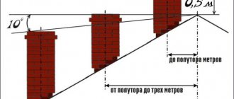
- Quite a high level of heat transfer. Depends on the brand of brick and its porosity. It can be eliminated by using the correct thermal insulation system and increasing the thickness of the external walls. For each region, the average annual temperature is taken into account and appropriate adjustments are made to the project.
- The number of freezing and thawing cycles that a brick can withstand without consequences is about 50 (depending on the type of brick). Installation of a vapor barrier together with high-quality heating reduces this indicator.
- The tendency to accumulate water in the pores, which, when frozen and subsequently thawed, leads to the destruction of walls. The use of waterproofing made from modern materials can save homeowners from this problem.
Design of brick houses
Before creating a house plan and design, you need to consider a number of points. For example, you need to understand that brick buildings, and especially two-story houses, have a lot of weight, which significantly affects the load on the foundation. Therefore, you should carefully study the properties of the soil on the land plot, resorting to the help of surveyors.
Calculation of heat losses at home
Based on the fact that the price of energy resources is steadily rising, and the whole world is concerned about the problem of energy conservation, a very important factor when choosing building materials is their ability to withstand heat losses. It is no secret that the larger the brick building, the more costs will be required to heat it. Considering that brick blocks are characterized by thermal inertia, we can conclude that a brick house takes a long time to heat up and takes a long time to cool down.
Table of heat loss of bricks and other materials
To increase the energy efficiency of brick houses, insulation materials are often used.
Brick selection
Thanks to the wide variety in the choice of building materials, you can choose a brick to suit every taste, size and color. By using porous bricks, you can increase the sound insulation of your home and also reduce heating costs. It should be understood that such properties also affect the cost of the brick, therefore, if you plan to build a house for summer use, the expenses will be pointless. For temporary residences, it is enough to use ordinary or sand-lime brick. Universal designs of brick houses are also suitable for the construction of buildings from other materials.
Design errors
Improper design of a two-story house can lead to cracks in the brick walls. The main reason is the incorrect calculation of the foundation and ground movement together.
Ready-made project for a one-story brick house with an attic
It may also happen that the foundation was calculated correctly, however, unplanned additions or structural elements not provided for in the design affect the load on the foundation. Cracks are repaired in several ways. If damage is caused by ground movement, the walls are reinforced with a metal belt. If the defects were formed due to errors in calculations, then restoring the wall will require large expenses. To repair, it will be necessary to replace the masonry, which will require some skill and great care.
GOST R 21.1101-2013 Basic requirements for design and working documentation
GOST R 21.1101-2013 Basic requirements for design and working documentation CONTENTS
- 1 AREA OF USE
- 2. REGULATORY REFERENCES
- 3. TERMS, DEFINITIONS and ABBREVIATIONS
- 3.1
Terms and Definitions - 3.2
Abbreviations
- 4.1
Project documentation - 4.2
Working documentation - 4.3
General data on working drawings
- 5.1
General provisions - 5.2
Basic inscriptions - 5.3
Coordination axes - 5.4
Applying dimensions, slopes, marks and inscriptions - 5.5
Images (sections, sections, views, callouts)
- 7.1
General provisions - 7.2
Permission to make changes - 7.3
Alteration - 7.4
Features of making changes to project documentation - 7.5
Features of making changes to working documentation
Codes of sections of project documentation
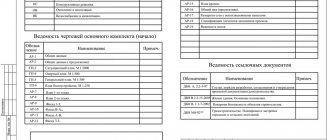
Brands of main sets of working drawings
Codes of attached documents
Statements of general data for working drawings
List of ESKD standards to be taken into account when performing graphic and text documentation for construction
List of allowed abbreviations of words used in graphic documents (addition to GOST 2.316)
Basic inscriptions and additional columns to them
Location of the main inscription, additional columns to it and dimensions of frames on sheets
Specifications
Permission to make changes
Change registration tables
Cover
Title page
Examples of title pages
Contents of project documentation. Composition of reporting documentation based on the results of engineering surveys
Preface
The goals and principles of standardization in the Russian Federation are established by the Federal Law of December 27, 2002 No. 184-FZ “On Technical Regulation”, and the rules for applying national standards of the Russian Federation are GOST R 1.0-2004 “Standardization in the Russian Federation.
Basic provisions" Information about the standard GOST R 21.1101-2013
- DEVELOPED by the Open Joint-Stock Company "Center for Methodology of Standardization and Standardization in Construction" (JSC "CNS")
- INTRODUCED by the Technical Committee TC 465 “Construction”
- APPROVED AND ENTERED INTO EFFECT by Order of the Federal Agency for Technical Regulation and Metrology dated June 11, 2013 No. 156-ST from 01/01/2014.
- This standard implements the norms of the Town Planning Code of the Russian Federation dated December 29, 2004 No. 190-FZ [1]
- INSTEAD GOST R 21 .1101-2009
1. SCOPE OF APPLICATION
This standard GOST R 21.1101-2013 “Basic requirements for design and working documentation” establishes the basic requirements for design and working documentation for the construction of facilities for various purposes.
Note.
In this GOST R 21.1101-2013, the concept of “construction” includes new construction, reconstruction, technical re-equipment and major repairs of capital construction projects.
The general rules for the execution and compilation of graphic and text documentation established in 4.1 and in sections 5 and 8, and the rules for making changes established in section 7, also apply to reporting technical documentation based on the results of engineering surveys for construction.
Return to top
2. NORMATIVE REFERENCES
GOST R 21.1101-2013 “Basic requirements for design and working documentation” uses regulatory references to the following standards:
2.1
GOST R 6.30—2003 Unified documentation systems.
Unified system of organizational and administrative documentation. Requirements for document preparation 2.2
GOST R 21.1001—2009 System of design documentation for construction.
General provisions 2.3
GOST R 21.1002—2008 System of design documentation for construction.
Standard control of design and working documentation 2.4
GOST R 21.1003—2009 System of design documentation for construction.
Accounting and storage of design documentation 2.5
GOST R 21.1703—2000 System of design documentation for construction.
Rules for the implementation of working documentation for water communications 2.6
GOST 2.004-88 Unified system of design documentation.
General requirements for the implementation of design and technological documents on computer printing and graphic output devices 2.7
GOST 2.051—2006 Unified system of design documentation.
Electronic documents. General provisions 2.8
GOST 2.052—2006 Unified system of design documentation.
Electronic model of the product. General provisions 2.9
GOST 2.101-68 Unified system of design documentation.
Types of products GOST 2.102-68 Unified system of design documentation. Types and completeness of design documents 2.10
GOST 2.105-95 Unified system of design documentation.
General requirements for text documents 2.11
GOST 2.106-96 Unified system of design documentation.
Text documents 2.12
GOST 2.109-73 Unified system of design documentation.
Basic requirements for drawings 2.13
GOST 2.113-75 Unified system of design documentation.
Group and basic design documents 2.14
GOST 2.114-95 Unified system of design documentation.
Technical specifications 2.15
GOST 2.301-68 Unified system of design documentation.
Formats 2.16
GOST 2.302-68 Unified system of design documentation.
Scales 2.17
GOST 2.303-68 Unified system of design documentation.
Lines 2.18
GOST 2.304-81 Unified system of design documentation.
Drawing fonts 2.19
GOST 2.305—2008 Unified system of design documentation.
Images - views, sections, sections 2.20
GOST 2.306-68 Unified system of design documentation.
Designations of graphic materials and rules for their application on drawings 2.21
GOST 2.307—2011 Unified system of design documentation.
Drawing dimensions and maximum deviations 2.22
GOST 2.308—2011 Unified system of design documentation.
Indications of tolerances for the shape and location of surfaces 2.23
GOST 2.309-73 Unified system of design documentation.
Designations of surface roughness 2.24
GOST 2.310-68 Unified system of design documentation.
Applying designations of coatings, thermal and other types of treatment on drawings 2.25
GOST 2.311 -68 Unified system of design documentation.
Thread image 2.26
GOST 2.312-72 Unified system of design documentation.
Conventional images and designations of seams of welded joints 2.27
GOST 2.313-82 Unified system of design documentation.
Conventional images and designations of permanent connections 2.28
GOST 2.314-68 Unified system of design documentation.
Instructions on the drawings for marking and branding of products 2.29
GOST 2.315-68 Unified system of design documentation.
Simplified and conventional images of fasteners 2.30
GOST 2.316—2008 Unified system of design documentation.
Rules for applying inscriptions, technical requirements and tables on graphic documents. General provisions 2.31
GOST 2.317—2011 Unified system of design documentation.
Axonometric projections 2.32
GOST 2.501-88 Unified system of design documentation.
Rules for accounting and storage 2.33
GOST 2.511—2011 Unified system of design documentation.
Rules for the transfer of electronic design documents. General provisions 2.34
GOST 2 512—2011 Unified system of design documentation.
Rules for the execution of a data package for the transfer of electronic design documents. General provisions 2.35
GOST 21.11 0—95 System of design documentation for construction.
Rules for fulfilling the specifications of equipment, products and materials 2.36
GOST 21.11 3—88 System of design documentation for construction.
Designations of accuracy characteristics 2.37
GOST 21.11 4—95 System of design documentation for construction.
Rules for the execution of sketch drawings of general types of non-standard products 2.38
GOST 21.302-96 System of design documentation for construction.
Conventional graphic symbols in documentation for engineering and geological surveys 2.39
GOST 21.408-93 System of design documentation for construction.
Rules for the implementation of working documentation for automation of technological processes 2.40
GOST 21.501—2011 System of design documentation for construction.
Rules for the implementation of working documentation of architectural and structural solutions 2.41
GOST 21.709—2011 System of design documentation for construction. Rules for the execution of working documentation for linear structures of irrigation systems
Return to top
3. TERMS, DEFINITIONS AND ABBREVIATIONS 3.1 Terms and definitions
GOST R 21.1101-2013 “Basic requirements for design and working documentation” uses terms from [1], GOST R 21.1001, GOST R 21.1002, GOST R 21.1 003, as well as the following terms with corresponding definitions:
3.1.1 title block
- a set of information about the design document contained in the columns of a table of the established form placed on sheets of design and working documentation.
3.1.2 main set of working drawings
- a graphic document containing necessary and sufficient information in the form of drawings and diagrams, intended for the production of construction and installation work of a certain type (brand).
3.1.3 complete set of working documentation
- a set of basic sets of working drawings necessary for the construction of a building or structure, supplemented by attached and reference documents.
3.1.4 brand
- an alphabetic or alphanumeric index included in the designation of working documentation and determining its relationship to a certain type of construction and installation work, or denoting the main distinctive features of building structures and their elements.
3.1.5 specification of equipment, products and materials
- a textual design document defining the composition of equipment, products and materials intended for acquisition, preparation and implementation of construction.
3.1.6 sketch drawing of a general view of a non-standard product
- a document defining the initial design of a non-standard product, containing a simplified image, basic parameters and technical requirements for the product in the amount of initial data (tasks) necessary for the development of design documentation.
3.1.7 non-standard product
- a product (structure, device, installation block) of technological systems, internal and external systems and networks of engineering support for buildings and structures, first developed and manufactured, as a rule, at the installation site (in the procurement workshop of the installation organization).
3.1.8 building structure
- a part of a building or structure that performs certain load-bearing, enclosing and (or) aesthetic functions.
3.1.9 construction product
- a product intended for use as an element of buildings, structures and building structures.
3.1.10 building structure element
- an integral part of a prefabricated or monolithic structure.
3.1.11 construction material
- material, including piece material, intended for the manufacture of building products and the construction of building structures of buildings and structures.
3.1.12 equipment
— technological equipment (machines, devices, mechanisms, lifting and other technical means that ensure the corresponding technological process), as well as engineering equipment of buildings and structures that provide safe and favorable conditions for people’s life.
3.1.13 coordination axis
- one of the coordination lines that determines the division of a building or structure into modular steps and floor heights.
3.1.14 plan
— a top view or horizontal section of a building or structure.
3.1.15 facade
- an orthogonal projection of the outer wall of a building or structure onto a vertical plane.
Note
: There are main, side, courtyard, etc. facades. 3.1.16
3.1.16 document details
— an element of document design containing information about it.
Note.
As a rule, a prop consists of attributes (composite props).
3.1.15 document attribute
— identified (named) characteristic of a part of the props.
3.1.18 document execution
— putting down the necessary details and attributes established by the documentation rules.
3.1.19 signature
— details of the document, which is a handwritten signature of an authorized official.
Note.
For electronic documents, an analogue of a handwritten signature is used - an electronic digital signature.
3.1.20 designation
— details of the document, which is its identification (distinctive) index.
Note.
Each document is assigned a designation, which is written down in designated places (in the main inscriptions, on title pages, etc.).
Return to top
3.2 Abbreviations
The following abbreviations are used in GOST R 21.1101-2013 “Basic requirements for design and working documentation”:
DE
— electronic document;
ESKD
- Unified System of Design Documentation;
CAD—computer-aided design system(s); SPDS
- System of design documentation for construction;
EDMS
is an electronic document management system(s).
Return to top
4. GENERAL REQUIREMENTS FOR THE COMPOSITION AND COMPLETION OF DESIGN AND WORK DOCUMENTATION 4.1 Design documentation
4.1.1
The composition of design documentation for capital construction projects and the requirements for its content are established by legislation [1], approved by the Government of the Russian Federation by Regulation [2] and regulations of federal executive authorities.
Project documentation is completed, as a rule, according to individual sections and subsections established by the Regulations [2]. The names and codes of sections of the design documentation are given in tables A.1 and A.2 (Appendix A). In paper form, design documentation is compiled into volumes in accordance with 4.1.4, 4.1.5 and section 8.
If there is a large volume (in paper form) of a section or subsection, as well as, if necessary, in other cases (for example, when involving subcontractors), it is allowed to divide it into parts, and parts, if necessary, into books. Each part and book are packaged separately. All parts and books are given names that reflect the content of the parts or books. Subsections, parts and books are assigned serial numbers in Arabic numerals within, respectively, a section, subsection or part.
4.1.2
Each section, subsection, part and, if necessary, book included in the volume, as well as each text and graphic document included in the volume, is assigned an independent designation, which is indicated on the cover, title page and/or in the main inscription, as well as in headers and footers of text documents executed without title blocks.
4.1.3
The section designation includes the basic designation, established according to the system in force in the design organization, and, separated by a hyphen*, the design documentation section code. The basic designation includes, for example, the agreement (contract) number and/or the code of the construction project (numeric, alphabetic or alphanumeric). The basic designation may include other codes used in CAD and EDMS.
If a section is divided into parts, then the part designation is made up of the section designation, to which the part number is added.
Project composition
Typical designs of brick houses include the following sections.
- Architectural section, including floor plan, facade drawings, necessary sections, roof drawing, general data and explanatory note.
- Structural part with masonry plans, choice of floors, drawing of the roof truss system.
- Section of engineering networks, including drawings and explanations of all life support systems of the house. These are: power supply, water supply, sewerage, home heating system, as well as various low-current systems (security and fire alarms, video surveillance, structured cabling networks, etc.).
Architectural section of a residential building project
The architectural section indicates the exact characteristics of the building geometry, structures, number of storeys, all dimensions and materials are reflected. All structural elements, such as windows, doors, partitions, are also described here. The drawings clearly mark the location of sanitary, kitchen premises, ventilation shafts, and indicate the thickness of walls and partitions.
In this section, designers will show the exterior of the building and the internal layout of the premises. This section also contains information related to ceiling heights, staircase placement, and use of usable space. Often the architectural plan contains information about the facade of the cottage, the color of the roof, the base, the placement of windows and doors.
The architectural section contains drawings of the vertical, transverse, and longitudinal sections of the house.
What not to do: 9 prohibitions
The requirements for text documents contain a number of prohibitions. For example, the requirements of the Unified System of Design Documentation (ESKD 2020) prohibit:
- Indicate indexes of standards without indicating the registration number assigned to them.
- Write mathematical signs without numerical accompaniment.
- Use a minus sign to indicate negative numbers.
- Cross out the circle to indicate diameter.
In the text itself it is unacceptable to use:
- Abbreviations of words, except those established by the rules of Russian spelling, relevant state standards, and also in this document.
- Turns of colloquial speech, technicalisms, professionalisms.
- For the same concept, various scientific and technical terms that are similar in meaning (synonyms), foreign words and terms in the presence of equivalent words and terms in the Russian language.
- Arbitrary word formations.
There are also requirements for physical quantities:
- You cannot abbreviate the designations of units of physical quantities (if they are used without numbers, with the exception of units of physical quantities in the headings and sides of tables and in the decoding of letter designations included in formulas and figures).
Deviation from the mandatory requirements is not allowed; any element of the text must be formatted in accordance with the current rules.
Engineering section
Provides for compliance of the project with the internal arrangement of the house. Simply put, water pipes are connected to where the sink or bathtub is to be placed. And electrical wiring makes it possible to connect the required number of sockets and switches in the room.
Very often, when designing, they forget that the finished plan must correspond to the intended design; the customer takes the first design sketch he likes. As a result, the layout that looks attractive in the drawings turns out to be completely unsuitable. We have to change the purpose of the rooms, try to arrange uncomfortable corridors. But it is not always possible to do this without losing quality and level of comfort. Therefore, it is not enough to understand what a private house project is and what it consists of; it is necessary to strictly monitor the compliance of the areas.
The engineering section involves planning:
- electricians.
- water supply and wastewater systems.
- ventilation and heating systems.
- placement of gas equipment.
Where can I find a ready-made plan?
A masonry plan for a country house can be ordered from any company that provides project promotion services. Designers offer their clients house plans developed by Russian architects in accordance with SNiP standards.
Important! When choosing a material for construction, do not forget that brick, cellular concrete and warm ceramics are interchangeable materials, so you can choose a masonry plan for a cottage made of foam concrete blocks similar to a brick house.
Basic concepts about masonry plans
Masonry plan is a drawing according to which a house is built. The specialist, guided by the diagram, knows what to make the walls from, insulation and soundproofing of the walls, and determines the connections of the openings and lintels.
This plan is worked out in as much detail as possible. The drawing indicates all the parameters and distances between the axes and the dimensions of the outer edges. Hatching on painted walls are symbols of materials by which the worker determines the type of masonry and its features. An addendum is additionally attached to the project, which describes in detail the location of stairs, verandas and other structures.
Structural section
This part of the design is aimed at not only making future housing strong and durable, but also avoiding overpayment for building materials.
It is divided into two sections: structures made of reinforced concrete (RC) and wood (WB).
It includes:
- foundation plan.
- floor plans.
- components and parts.
Essentially, these are instructions for the construction crew. Builders do not need to think about what should be included in the project of a private house; they already have it in the form of a ready-made design. Workers will not have to remember, for example, how they laid floors or poured a floor at another facility in order to repeat the manipulations. All calculations for them have already been made by more competent specialists.
Regarding design solutions, the designer is responsible for compliance of quality indicators with the established ones. It is he who understands the resistance of materials, develops structures and calculates the maximum load. He knows how to make a building strong, reliable and durable and takes full responsibility for the quality of work.
To select the right contractor who has a thorough understanding of low-rise building codes, search the Building Companion directory. The profile of each company contains the necessary information, portfolio, reviews, and you can place a request for an estimate of the cost of the service. Find a general contracting and construction supervision company »
Why do some people offer a complete project for 30 thousand?
A very attractive amount, but don’t rush to rejoice. You can purchase a ready-made plan with all the accompanying sections for that kind of money. But it is necessary to understand that it will turn out to be typical, without the possibility of making any adjustments to it. The cheapness is explained by the fact that after its creation it was already sold many times. And the serial version is always much cheaper than the individual one.
Having one hundred percent confidence that this option will suit you, you can safely buy from reputable developers.
We have already discussed what the project of a private house should be, what it includes and who draws it up. When purchasing a ready-made product, 99% out of 100 there is a need to make changes, even minimal ones. This is how a person works, who always strives to adjust something to his needs and preferences. But making adjustments to previously drawn up drawings for free will not work. This is a very difficult and painstaking task that requires maximum effort from specialists.
Approval of the project to begin construction
The need to adjust the project. Even if you yourself were able to depict the house of your dreams on paper, you will still need to consult with specialists before starting construction of the house - the opinion of a competent foreman or architect will not be superfluous. At a minimum, the following points will need to be agreed upon:
- Carrying out electrical work;
- Conducting your own sewerage system;
- Carrying out water supply;
It is necessary to understand that all the above issues are not an artistic or architectural part of the project. These are all the most routine issues, a competent approach to solving which is provided only by professionals in their field. As a last resort, any oversight in independently drawing up a house project, which was made by a person who does not have a specialized education, can be corrected by a competent foreman who understands the practical side of any idea much better. Although even if the project is drawn up by professional architects, purely practical shortcomings cannot be ruled out.
Independent work on a house project and its advantages
You can create the design of your house yourself - in order to develop drawings of the relative position of certain rooms, as well as determine the place of the house on the site, you do not need special knowledge. A competent and responsible approach to business will ensure the success of your event. However, in terms of communications, it will be necessary to consult with professionals. This way you can properly plan a house that will serve you faithfully.
Read about the following stages of construction:
Types of foundations used in construction
Which is better to choose a foundation for the soil and type of house
Water supply for a private home
Watch also the video on how to make a house project yourself
Read about the previous stages of construction:
Layout of land for building a house