Let's try to figure out how at home, without having complex specialized measuring instruments and electronic devices, you can determine for yourself where the phase is, where the zero is, and where the ground is in the wiring.
Of all the known methods, the simplest determination of phase and zero, we have selected the most, in our opinion, accessible to implementation and at the same time safe. For this reason, in the article you will not see advice on how to find the phase using potatoes or calls for briefly touching the wires with various parts of the body.
In fact, there are not so many options for determining phase, zero or grounding, for example, in a socket, without the use of specialized equipment, and sometimes, depending on your goals and objectives, it is enough just to know the standard for color marking of electrical wires adopted by us to distinguish them.
Basics of functioning of grounding systems
Potential may accumulate on the housings of some electrical devices (with high conductivity, for example, metal) due to the ingress of current in the event of a breakdown of the insulating layer of the wiring. If there is such a malfunction, any touch to the body of the device is fraught with the passage of current from the device to the “ground” through the person (from the hand and then along the body and leg to the “ground”). Under unfavorable circumstances, this can lead to death, because Only 100 mA is enough for the damaging processes from an electric shock in the human body to lead to irreversible consequences.
As you know, electric current tends to pass through conductors with the lowest resistance. This property serves as the basis for the functioning of any protective grounding system. In essence, grounding is the connection of metal parts of electrical installations with a conductor of maximum capacity and minimum resistance, which reliably protects a person from electric shock if it hits the device body.
The human body, consisting mainly of water, is considered a good conductor with a nominal resistance of 1000 Ohms. Calculations show that electric current will “pass by” a person if it flows through a conductor with a significantly lower resistance, which does not exceed 4 Ohms and 8 Ohms - at a voltage in the circuit of 380V and 220V, respectively. It is these values that are indicated in the PUE and you need to focus on them.
Regular testing and measuring of grounding, discussed below, can prevent possible negative consequences in advance.
Schematic representation of the grounding system for almost any household appliance Source gradusplus.com
The power cable of any modern electrical device contains a special wire that connects the device body to a separate contact on the plug. When this plug is inserted into an outlet, this pin makes contact with the grounding terminal of the outlet, and therefore with the entire grounding of the structure.
If, due to damage to the wiring, an electric current leaks, the latter will go into the ground through the grounding wiring, which has minimal resistance. For this protection to work properly, resistance indicators are of key importance, monitoring which makes it possible to prevent and prevent possible accidents.
Useful tips and general recommendations
Before work, check the phase indicator on a conductor or terminal known to be connected to the current source. If there is little space in the distribution board, purchase a socket RCD.
The rated amperage of the residual current circuit breaker must be one step higher than that of the circuit breaker protecting it. If this condition is met, the device will be protected from operation in overload mode.
If the RCD is triggered falsely due to large leaks in the old wiring, instead of a 10 mA device, install a 30 mA analogue.
After connecting the wire to the terminal of the socket or distribution box, pull it to check that it is securely fastened.
In the bathroom, sockets with a dust and moisture protection class of at least IP44 are installed. The minimum height above the floor is 30 cm.
The need for regular checks
The need to maintain the serviceability of the ground loop is considered a prerequisite for the effective functioning of the system. Therefore, a periodic grounding test with a multimeter (as the most accessible tester for the average person) is needed, the results of which will determine the performance of the circuit.
If the grounding is in normal working order, any emergency situation that arises will lead to the discharge of electric current through the grounding conductor into current-carrying elements located in the ground, from which the electric discharge will quickly and uniformly spread deep into the soil.
Grounding diagram for a private house Source sovet-ingenera.com
See also: Catalog of companies that specialize in electrical work of any complexity
The reliability of any electrical circuit is inversely proportional to the number of conductor connections - the fewer, the better. But in any case, it is impossible to get rid of them completely. In addition, it must be taken into account that some of the connections are in the ground and from prolonged contact with it, an oxide layer is formed on the metal of the current-carrying electrodes, leading to the inevitable formation of a corrosion layer.
The result may be an increase in the resistance of the device elements and the occurrence of obstacles to the flow of current. Plus, the presence of any substance with increased chemical activity in the area of soil that includes grounding leads to the fastest possible occurrence of rust, since the metal parts of the circuit constantly interact with the soil.
Over time, corrosion leads to the formation of individual flakes that begin the process of peeling away from the metal, thereby deteriorating the electrical contact. Because of this, the circuit resistance increases, because the number of these corroded areas becomes large. The grounding device loses electrical conductivity, the likelihood of incomplete discharge of electric currents into the soil increases, and the overall level of protection decreases.
As a result, the inspection usually begins with an assessment of the technical condition of the circuit and its components.
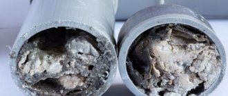
An example of corrosion of a grounding device Source gidpokraske.ru
Measuring the ground loop resistance makes it possible to verify the safety of the system. Technically, this calculation of resistance is based on Ohm’s law, known to everyone from the school physics course. If the voltage and current in the current source are known, or we can measure it, then it is enough to simply determine the resistance by dividing the voltage by the current. But the practice is somewhat more complicated and has a number of features and measurement rules that require their strict implementation.
What to consider
When using outdoor lighting on metal supports, grounding plays a key role in ensuring the safe operation of lamps. And this part of the PUE is regulated. When installing external lighting, you need to rely on the following points of the PUE:
Grounding the luminaire
- on all types of lamps used in outdoor lighting systems, protective grounding is mandatory and there are no exceptions;
- Grounding is organized using special grounding devices. These devices are designed for re-grounding, as well as protection against lightning surges and grounding of electrical equipment (luminaires) that will be mined on supports;
- the resistance that the grounding device must have is no more than 30 Ohms;
- Protective grounding for metal housings of local lighting lamps with voltages above 50 V involves the use of protective conductors. They are attached to the metal structure on which the lamp was installed. And a reliable electrical connection must be created for the bracket and the housing;
- for lamps, as well as for supports, grounding against atmospheric voltage is necessary;
- the total spreading resistance for grounding conductors (of any type) using reused PEN conductors should be within the range of no more than 5, 10 and 20 Ohms (depending on the line voltage).
PUE standards are developed for different situations, but have more or less universal application.
Professional measurement (using a megohmmeter)
The generally accepted grounding measurement includes the following sequence of actions:
- Visual inspection of connections on bolts and welded contacts should be carried out;
- take resistance readings of the entire circuit;
- check the resistivity of the soil layer.
Measurements are carried out using special instruments. The megohmmeter that is best suited for this is considered optimal.
Megaohmmeter – model M-416 Source pribor-service.ru
Video description
Briefly about the theory and practice of using ohmmeters M-416 and M-4001 is described in this video:
- The rod of the probe and the accessory electrode are driven into the soil to a depth of over half a meter. This is done on soil with natural density (not poured or loosened) by hammering it in with a sledgehammer.
- At the junction of the grounding wire and the electrode, it is important to clean off the remaining paint coating. Copper wires with a cross-sectional area of 1.5 mm² are used.
- It is recommended to begin direct work on measuring the resistance of protective devices by selecting the “x1” range. After pressing the red button, the handle of the device rotates until the arrow reaches the zero mark. Higher resistance values should be measured by choosing larger ranges - “x5” or “x20”. For measuring the resistance of the protective circuit, the indicator “x1” is used, which is sufficient to display the results on the instrument scale.
It is optimal to carry out such measurements in the most dense soil and in dry summer weather conditions. You can make the same measurements in winter, but it is recommended to do this during frosts, when the soil is frozen as much as possible. It is not advisable to take measurements in wet weather, because... the data obtained will be greatly distorted and therefore unreliable.
Checking grounding with an electronic megohmmeter Source uk-parkovaya.ru
Typical socket design
Using the socket grounding test technique may be necessary at any time. Especially for those people who will have to work with specific electrical outlets repeatedly.
This part of the electrical network (domestic or industrial) has a simple design.
The electrical outlet does not shine with design difficulties. A simple ceramic or plastic base plus a metal frame with a lid. Still, electrical outlets are improving.
The electrical outlet consists of a round or rectangular plate. The plateau is made from materials that do not conduct electricity.
Typically, the following is used to make socket plates:
- ceramics;
- porcelain;
- plastic.
The back of the plateau has a flat surface, and on the front there are shaped landing pads for electrical contactors. The material of contactors is usually copper. The contactors are fixed to the plateau rigidly - using rivets, plus they are embedded in the body of the plateau.
For connection to electrical wiring, the contactors have mounting screws. This entire structure is closed with a lid that has two passage holes for an electrical plug.
Checking grounding in a home network (using a multimeter)
As a rule, in new housing, the electrical network has already been wired, so you need to know how to check the grounding resistance of already installed household outlets.
This work should also begin with a visual inspection of the item being measured. You should turn off the power and remove the protective cover of any of the sockets that are equipped with a special terminal for connecting the ground loop conductor (usually a yellow-green wire). If only two wires are connected to the contacts (phase and neutral, usually brown and blue, respectively), then this clearly indicates the absence of grounding.
If the third wire is still present, this does not guarantee its proper functioning. It is necessary to carry out a special test procedure with a multimeter. The sequence is as follows:
- The input circuit breaker is turned on so that there is voltage in the network (sockets).
- The tester switches to voltage measurement mode - usually this is the “ACV” icon.
Determining the phase position by the color of the wire insulation
The neutral working wire is equipped with blue insulation, the ground is yellow-green. Accordingly, the phase has a red (brown) color. The rule can be grossly violated. Older houses were often equipped with two-core wires. The insulation color in each case is white. Some devices, such as light or motion sensors, have a different layout. For example, the neutral wire is black. Here, get ready to look at the instruction manual, there are countless layout options.
Video description
This short video shows how to check the grounding of a socket using a multimeter:
- The probes of the device are applied to the contacts, and the voltage between the phase and neutral wires is measured. For a home network it should be standard 220V.
- Similar measurements are made with a multimeter with phase and ground - the result should be approximately the same as in the previous measurement. If the instrument scale shows a lower voltage reading, it means the grounding is not working well. If the device does not respond when the probes touch the contacts, it means that the ground loop is not connected or is faulty.
Even when there are no measuring instruments in the house, it is possible to check using available means. You will need a homemade device in the form of a light bulb screwed into a socket, from which extend pieces of wire with stripped contacts at the ends. People call it “control”. Such a device is sometimes used by self-taught electricians (and not only), but, as a rule, its use is not recommended by professionals.
To check, one contact of the “tester” is in contact with the phase, and the second is in contact with zero. When the light comes on, it indicates the presence of voltage. Then the contact from zero is moved to the ground wire. The operation of the light indicates the presence of a working protective system. A weak or intermittent glow indicates problems in the circuit, and a complete absence of light indicates its complete malfunction.
Appearance of the panel of the most common electronic multimeter with explanations for use Source lifehacker.ru
Rules for grounding a washing machine with your own hands
Before work, prepare the following tools:
- phase indicator (indicator screwdriver);
- multimeter;
- wire cutters;
- screwdrivers with Phillips and flat blades.
The procedure depends on the type of residential property.
In the apartment
In new buildings they operate in the following order:
- Knock out a hole for an outlet in the wall next to the machine.
- They punch a groove to it from the junction box.
- A 3-core wire with a cross-section of 2.5 square meters is laid in the furrow. mm.
- Connect conductors to each of the 3 contacts of the socket.
- Turn off the input circuit breaker and connect the wires to the corresponding terminals in the distribution box or panel.
- Check the functionality of the system.
- They turn off the power to the apartment again and complete the installation of the electrical point, then seal the groove with cement mortar.
If the supply line is drawn from the switchboard, the protective conductor is closed to the PE bus.
In a private house
In the private sector, the TN-S system is not used due to its high cost, TN-CS - due to the vulnerability of the line between the consumer and the substation (there is a high probability of a neutral break above the point of splitting of the combined conductor into protective and neutral). Instead, the TT type is in use here, which involves installing its own ground electrode for each house.
The design consists of 3 electrode rods, which can be used as:
- pipes with a diameter of 3–5 cm with a wall thickness of 3.5 mm;
- strip steel or angle with a thickness of 4 mm;
- rod with a diameter of 10 mm.
The length of the pins is selected so that when deepened they sink at least 30 cm below the freezing mark of the soil. However, they cannot be shorter than 1.5 m.
Sequencing:
- Dig a hole 0.5 m deep.
- The electrodes are cut obliquely with a grinder to sharpen the end, and driven into the bottom of the recess at a distance of 1.2 m from each other (at the vertices of an equilateral triangle).
- A steel strip is welded to the shanks protruding from the ground, combining the rods into a single structure.
- Connect a current conductor - a strip or cable 5 mm thick - to the ground electrode.
- They bring it into the house and connect it to the PE bus.
- They fill up the trench.
Next, connect the devices in the house to the PE bus as described in the previous section.
In Khrushchev
Most Khrushchev buildings use the TN-C system, which means there is no PE bus. It is recommended to install an RCD at the entrance to the apartment. The phase and neutral from the meter are connected to the upper terminals, the wires to the apartment are connected to the lower terminals.
In order for the RCD to be triggered immediately after a phase is shorted to the housing, before the user touches it, the washer is reset to zero. The protective conductor is connected to the neutral above the residual current switch.
Briefly about the main thing
The resistance of a properly functioning grounding should be 4 Ohms. Since the resistance at the conductor connections may increase over time, the grounding must be checked regularly - approximately every 12 months.
There are several ways to measure the grounding resistance of a home network. Professionals carry out this work using a device such as a megohmmeter. At home, you can use a standard multimeter or even a homemade “control”, but you need some experience to correctly interpret their readings.
In general, tests are based on Ohm's law - the voltage in the circuit and the current are checked and the resistance is calculated from them. The measurement procedure is quite simple and can be done by the average person if he knows the basics of working with electricity and electrical safety rules. If you have doubts about your skills, it is recommended to seek the services of specialists.
Ratings 0
Indirect evidence of the absence of PE
There are some situations that indirectly confirm that the PE circuit is not working, is not connected or is working very poorly.
- Household appliances connected to water give a slight electric shock. These include a washing machine, dishwasher, water heater, electric kettle and others.
- There is noise in the speakers when playing music.
These are the simple ways to determine whether a wired PE system is working or not. And one more warning. It cannot be connected to a lightning rod or used for heating. Neither system is designed for these needs.
If you find an error, please select a piece of text and press Ctrl+Enter.