Ensuring good ventilation in the bathroom is a very important task. The lack of proper air exchange in this room will not ensure a comfortable stay for a person. A timer for a bathroom exhaust fan is an incredibly convenient feature. It will turn on the hood when the light in the room is turned on and turn it off after a certain time has passed after it has been turned off.
In residential and public buildings, a ventilation system is necessarily provided, which functions due to the natural flow of air, but ventilation ducts tend to become dirty over time and can no longer fully perform their main function. You can determine this in the bathroom by the following simple signs:
- the unpleasant odor lasts for a long time;
- mirror surfaces sweat;
- Condensation accumulates on walls and plumbing.
If one of these signs is present, you need to take care of installing an exhaust fan. You can purchase a timer for a fan and install it yourself, or buy a fan with a built-in timer.
How does the device work?
If the bathroom lights are turned off, the hood fan will also be turned off. In this case, the current consumption will be minimal, which will not even be recorded by electricity meters. This is the so-called standby mode.
When you turn on the lighting in the bathroom, the timer begins counting the period of time before turning on the hood, which lasts approximately 15 seconds (deviations by 1-2 seconds are possible). If you manage to turn off the light before this time is up, the fan will not turn on at all. For example, a person entered the bathroom to put or take something, which took a matter of seconds, but the hood would not turn on. This is very convenient because there is no need for the hood to operate. When the light is on for more than 15 seconds, the timer will turn on the hood fan, and it will work as long as the light is on and after it is turned off for 5 minutes. In addition, for every 2 minutes the light is on, the fan operating time after turning off is extended by another 1 minute. After turning off the light, the hood can operate for a maximum of 30 minutes. For example, if a person went into the bathroom and turned on the light, after which he stayed there for 15 minutes (took a shower or bath), then the operating time of the hood after turning off the light will be 13 minutes (5 minutes + 15 minutes/2 = 13 minutes).
The fan timer also provides the following program: after the light is turned off, the fan operating time will be the same as it worked when the light was on. Different timer fan models may have different operating intervals.
If the fan is running and the light in the bathroom is turned on again, then the duration of the fan operation will be determined as the sum of the remaining time that has not yet ended and a new period of time, which can be calculated using the described method.
The LED flashes every second to indicate that the device is operational and ready for use.
Devices with light sensors
There are also timers with light sensors that react specifically to the presence of lighting. They no longer need the command wire from the lamp.
As a rule, the exhaust fan is mounted under the ceiling in the wall of the bathroom, so that when the lights are turned on, it will be as brightly illuminated as possible. For the timer to work correctly, there must be a significant difference when the bathroom lighting is on and off. If the bathroom is so light that the hood does not stop working, you need to paint over the LED with varnish to reduce the amount of light or deepen it.
It should be remembered that the timer elements are live, which is why you need to be extremely careful when installing the device or when testing it. The danger increases because the installation is carried out in a room where the risk of electric shock is high due to humidity.
Design and operating rules
The timer is a single-sided printed circuit board on which the elements are mounted. Component DD1 is connected on the conductor side, the remaining components are installed on the other side.
To protect the printed circuit board from moisture, it is recommended to open it with moisture-resistant varnish.
The most common type of timer is connected to a 220 V network and has a signal wire input from a lighting lamp. In other words, the timer is always connected to power, and the fan is already connected to it. When you turn on the light in the bathroom, a signal is sent to the timer and the time begins counting down, after which the hood turns on. When the light is turned off, the power on the signal wire disappears and the countdown begins until it turns off.
What to do if the hood does not work completely?
What to do if the hood in the kitchen is completely broken and won’t turn on? It's difficult to repair without a technician. You will see that nothing is working: the fan is standing still, there is no light, and so on .
First, check the wiring again. Is everything okay with the cord, or is it broken, is the socket working, etc. If the reasons cannot be found, we call back the entire chain.
You need to check the switch especially carefully for burnt contacts. And look at the condition of the fuse, as well as the capacitor, so that it is not swollen .
You have checked everything, there are no faults, the engine is probably broken. As a rule, it is expensive to repair and it is easier to purchase a new one.
Replacing the engine yourself:
- Unplug the hood.
- Pull out the filters.
- Open the bottom panel.
- Turn off the backlight.
- Remove the hood from its niche.
- Disconnect the fan from the motor, usually by removing the clamp.
- Remove the electric motor. You need to unscrew the screw, disconnecting the green ground wire, and then cut the wires from the engine.
- Unscrew the fasteners and remove the engine.
- Attach the new motor to the mounting plate and place it inside the device. Don't forget to connect the motor, including grounding.
- Reinstall the fan, securing the clamp.
- Hang the hood on the bracket, connect it to the network and check the operation.
Fan connection diagrams
How can you implement the wiring diagram for a fan with a timer from Era or any other manufacturer? It’s worth noting right away that you don’t have to entrust such work to specialists; you can do everything yourself. At the same time, installing the device itself is not a problem, and that’s only half the battle. The main thing is to apply voltage to it. And since we are considering fans that are equipped with a timer, there are not many options:
- Connection via a switch - that is, parallel to the lighting.
- Connection directly to the distribution box - a fully automated system without human intervention.
It is worth noting that all these options are best implemented at the stage of renovation or construction of a new facility. Then the wires will be securely hidden under the tiles or plaster. Otherwise it presents certain difficulties.
Primary diagnosis
Often the hood does not work due to problems with the electrical wiring, so we check it first. But if you don’t understand anything about electrics, it’s better to call a specialist.
So, when the hood at home does not work, you need to make sure that everything is in order with the outlet. If other equipment is turned on from the same outlet, the wire or contacts in the device itself may be damaged. Check the wire and plug for damage. And inspect the contacts.
Everything is fine? Then we next look at the switch through which voltage is supplied. Ring the wire, conductors and switch. If it does not work in the “On” position on the switch, then that means the reason is there.
To accurately check that there are no contacts in the switches, you need to connect the conductors without it and plug the device into the network. Happened? Therefore, the switch needs to be repaired or replaced.
The cause of a hood breakdown may be due to the protection elements installed in the device. You need to see the fuses; it happens that over time they burn out and must be replaced.
Next we will tell you how to fix other breakdowns if no problems are found with the wires.
Fans with a timer are a good solution
We have already become familiar with the need for a forced ventilation system - it is enough to install an exhaust device. However, in comparison with conventional models, analogues with a clock device have much greater advantages. By implementing in practice the connection diagram for a fan with a timer, you can bring the ventilation to almost ideal.
First of all, we are talking about saving electrical energy. The fan, which is powered in parallel with the lighting, will turn on even when the owner simply goes into the bathroom to wash his hands or load dirty laundry into the washing machine. That is, the device starts working even if there is no need for air exchange.
The operation of models with a timer is due to a long stay in the bathroom and in this case it is no longer possible to do without air circulation. As a result, the fan functions, as they say, strictly to the point.
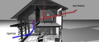
Why ventilate your bathroom?
Connection instructions
The bathroom often has a small area, so without constant air circulation the humidity level will be very high. This will promote the appearance of fungus, mold and other microorganisms. In addition, the service life of many building materials used in furnishing the premises may be significantly reduced. Since the bathroom does not have windows, the only way to maintain normal humidity is to use installed ventilation systems. They are usually designed to maintain air circulation without additional devices. You can check if this is enough by placing a sheet of thin paper against the hole and releasing it. It must be held due to the difference in pressure inside and outside and not give in. If this does not happen, you need a fan that will provide forced air circulation and lower the humidity level.
Option - manual switching on, switching off delay
Here you will need a special fan with a built-in timer. On average, it is about 500 rubles more expensive than usual. You need to place a button on the wall (monostable switch), pressing which will turn on the fan for a specified time. That is, we can turn on the hood ourselves when we need it. You need to provide this button in advance and put some clear pictogram on it, but the fan will not make noise when it is not needed.
If you take a slightly more advanced fan with a humidity sensor, it will automatically turn on when the humidity rises, that is, when someone uses the shower.
By the way, I have implemented this option at home. I personally find it the most convenient.
Humidity sensor and bathroom hood upgrade
With the holidays approaching, there is more time to finish all the little things that were left “for later” during the renovation of the apartment. Today we got around to using the hood in the bathroom. It infuriates me when the exhaust fan is placed in the same circuit as the ceiling light - it makes noise and goes on even when you go into the bathroom for a second to wash your hands. In addition, the hood turns off immediately after you take a shower and get out - and whether there is still dampness in the air or not does not matter.
I decided to do it wisely. The solution using Arduino is under the cut. Attention - the review describes operation with a mains voltage of 220 volts. If not properly trained, operating errors can result in electric shock or death. Assess your skills realistically, be careful and respect the PUE.
I immediately answer the age-old objections about forced ventilation
* The house is old, pre-revolutionary - each apartment has its own individual ventilation duct to the attic. My “exhaust” will not come out to any of the neighbors. * There is natural draft in the ventilation duct and it is sufficient - it was checked with an anemometer, the stopped fan does not interfere with it. The purpose of the fan is to quickly remove moisture.
In the vastness of Ali there are 2 types of humidity sensors - DHT22 and DHT11. The second type is cheaper, but there are a lot of complaints about it, so I settled on DHT22.
During the repair, I laid a “twisted pair” parallel to the power cables and took care of the junction boxes to accommodate the Arduin. At some point, I plan to power all the Arduins in different corners of the apartment via PoE from the only high-quality power supply, through an extra pair of conductors, but for now I’ve limited myself to tearing apart the old, well-deserved Nokia charger for 5V and 300mA. In order for it to fit into the junction box, I moved it from its original case into a box for a telephone socket, soldered the leads and fixed it with hot glue. Heating is checked; at low loads the device remains completely cold:
I remove from the frame behind the suspended ceiling a fan (I don’t remember the model - some of the most budget ones from Leroy Merlin) and the low-voltage circuit laid to it (it was there that the last 3 m from the twisted pair bay at 300 m were missing and I had to use a telephone cable for 4 cores):
We take the hero of our review, glue the gap between the board and the sensor so that it is held not only on the solder leads. We select a screw for fastening (M3 is suitable):
We drill a 3mm hole in the side of the fan and fix the sensor inside the ventilation duct near the blades. We attach DuPont connectors to the ends of the telephone cable and insulate them with heat shrink. Keeping in mind that the assembly will be affected by motor vibration, we fix the connectors on the “legs” of the DHT22 sensor with varnish, and we also cover the tracks not protected by the board mask with it. The result is that the sensor is securely fixed, has excellent ventilation, and minimally interferes with the air flow. We cut off the extra fourth core at the root (we were too lazy to ground it).
[Update: the comments rightly noted that the sensor needs to be wrapped to protect it from dust. A non-woven cloth works well.]
Since cutting the telephone cable turned out to be shameful (more shameful than many cheap Chinese USB cables - it turns out that this is possible!) We first test whether the sensor “sees” the Arduino. We take the first UNO we come across from the desk drawer, attach connectors to the wire, and plug it into the Arduino. We connect the power to VCC and GND, the signal line to any digital pin. I crimped the wires with the cheapest crimper for 12 bucks - no matter how intimidating my respected colleague yurok
, the result is decent.
In Arduino version 1.6.7, the library for working with the sensor is connected from the repository - it can be easily found using the keyword “DHT22”:
After connecting, a new one appears in the “Examples”, called “DHTester”. Let's take it. Don't forget to correct the pin number in the line
#define DHTPIN 2 // what digital pin we're connected to is the one into which the signal wire from the sensor is plugged.
We load the example into Arduino, open the Serial monitor and are relieved to see that data is coming from the sensor, even over three meters of crappy wire.
We close the door to the bathroom and turn on the shower. We establish experimentally that humidity more than 72% is the “threshold” from which forced exhaust must be turned on. Then we draw your attention to the fact that the numbers, albeit slightly, do vary. It becomes clear that we need to take several measurements in a row and calculate a “moving average” from them.
We begin to assemble the structure so that it fits into the wiring. To control the hood, we take a small relay from old supplies.
I decided to simply glue the components to the inside of the junction box lid with liquid nails. This is more reliable, simpler, and ensures insulation of the relay contacts on the bottom side of the board. The control was entrusted to the Arduino Mini - it’s not a pity to wall up a hundred-ruble board in the wall.
I highly recommend writing all contacts and other useful information with a marker there, on the inside of the lid. In a year, without this, you won’t remember what clung to where and why.
We connect the assembly to the network, not forgetting to turn off the power to the desired zone in the distribution panel. I fix the soldered contacts, which I made from twisted pair scraps, with the same “liquid nails”, because... Single-core Cat5 copper wires are very prone to breaking. All power connections are made using Wago terminal blocks.
We connect the Arduino Mini to the computer via a USB-TTL adapter. I was too lazy to solder the fifth wire to the DTR line, so we just hold down the Reset button on the Arduino with our finger, press Upload and then release Reset.
Code (don't hit me with a slipper)
#define DEBUG 1 // If changed to “0”, less memory will be required #include “DHT.h” // Standard library, included in the “Sketch” menu -> “Include library” -> “Manage...” #define DHTTYPE DHT22 // If you are not using DHT22, you need to change #include // Source - https://github.com/MajenkoLibraries/Average #define relaypin 9 // The relay is attached to pin No. 9 #define dht22pin 5 // The sensor is attached to pin No. 5 DHT dht(dht22pin, DHTTYPE); Average ave(10); // To average the latest values from the sensor, create an array of 10 pieces. float float treshold = 72; // Percentage of humidity, upon reaching which we turn on the fan unsigned long runInterval = 300000; // If we turn on the fan, then for no less than 5 minutes (5 * 60 * 1'000 milliseconds = 300'000) unsigned long idleInterval = 120000; // Whatever the humidity, after turning off we give the motor a 2-minute break // unsigned long previousMillis = 0; const long interval = 1000; // Poll the sensor with one-second intervals unsigned int i = 0; // Counter void setup() { pinMode(relaypin, OUTPUT); digitalWrite(relaypin, HIGH); // By default, the fan does not work (connected to the “NO” - “normally open” relay connector) if (DEBUG == 1) { Serial.begin(9600); Serial.print("Starting, humidity threshold set to: "); Serial.print(treshold); Serial.println("%."); } dht.begin(); } void loop() { if (DEBUG == 1) { Serial.print(i); i++; Serial.print(": "); } float t = dht.readTemperature(); // Query the sensor float h = dht.readHumidity(); if (isnan(h) || isnan(t)) { Serial.println("Sensor error!"); delay(interval); return; } else { ave.push(h); // Put the humidity measurement result into an array. The array fits 10 dimensions, the newest one pushes out the oldest one. if (DEBUG == 1) { Serial.print("Humidity: "); Serial.print(h); Serial.print("%\t"); Serial.print("Humidity running average: "); Serial.print(ave.mean()); Serial.print("%\t"); Serial.print("Temp.: "); Serial.print(t); Serial.println("C"); } if (ave.mean() >= treshold) { // Calculate the “moving average” based on the last 10 measurements, compare it with the threshold value digitalWrite(relaypin, LOW); // If the humidity is high, turn on the fan... if (DEBUG == 1) { Serial.println("Fan started."); } delay(runInterval); digitalWrite(relaypin, HIGH); // ...and then let it cool, no matter what humidity remains. if (DEBUG == 1) { Serial.println("Fan will cool down."); } flushData(); // After we have cooled the motor, we need to “clean” the array with humidity measurements with current measurements. Otherwise, the engine will start again and again. delay(idleInterval); } } delay(interval); } void flushData() { int k = 0; if (DEBUG == 1) { Serial.println("Flushing sensor readings."); } while (k < 10) { float t = dht.readTemperature(); // Query the sensor float h = dht.readHumidity(); if (isnan(h) || isnan(t)) { Serial.println("Sensor error!"); delay(interval); return; } else { ave.push(h); // Put the humidity measurement result into an array. The array fits 10 dimensions, the newest one pushes out the oldest one. } k++; delay(100); } }
The operating logic is simple - Arduino takes humidity measurements and calculates the average of the last ten. If the humidity exceeds the threshold specified by the “threshold” variable, the fan turns on.
To avoid jerking the motor frequently, the fan is turned on for at least 5 minutes. Then, regardless of what humidity is reached, we give the fan 2 minutes to cool down. Then the queue of measurements is cleared, Arduino makes new measurements and the cycle repeats.
For the final test, in order not to arrange a “bath” again, we set the treshold to 30%. We turn on the water and make sure that everything works as it should. As you can see from the screenshot, as soon as the moving average exceeded the threshold, the fan turned on:
We return the “working” humidity value to 72%, unhook the USB-TTL adapter and carefully close the lid. We make sure that the LEDs do not shine through and the structure does not heat up.
We collect everything, sweep, rejoice:
PS During the process of writing the code, it became clear that it would need to be improved in the summer. From the screenshots you can see that thanks to the heated towel rail, my bathroom is at 28C. During a summer water outage, the temperature in the bathroom will drop and this will affect the calculation of relative humidity by the sensor. We'll have to look at it and maybe rework the logic.
PPS It would be worthwhile to install a fuse in the circuit to the fan, but there was no “cable-mount” suitable for such a case at hand. I'll buy it later and install it.
(All the junk mentioned in the review was purchased at different times with my own money, for some reason they don’t offer “freebies” even after a couple of tens of thousands left on AliExpress 
Features of the right choice
When using a fan connection diagram with a timer in a bathroom or toilet, the choice of the device itself is also of considerable importance. To do this, you must first pay attention to its main characteristics:
- performance;
- electrical safety;
- noise level.
The performance of the appliance is largely determined by the volume of the bathroom, including the number of people using it. To calculate this parameter, you need to remember one formula, well known from school: multiply three quantities together: length, width and height.
After this, the obtained result must be multiplied by the frequency of ventilation. According to SNiP, this figure for a family of three is 6, for a larger number of people it is 8. The number will ultimately be the fan’s performance. In this case, it is better to choose a device with a value slightly larger than the calculations obtained.
In the connection diagram for a fan with a Vents timer, for example, the degree of electrical safety is no less important than performance, if not more. And since the device must operate in a room with a high level of humidity, then this indicator should vary from IPX3 to IPX5. This indicates that the device body is reliably protected from splashes and moisture, including direct contact with a jet of water. It is not worth purchasing one of the options with a higher protection class for a bathroom in an apartment or private house due to its inexpediency. This is not an industrial premises.
Regarding the noise level, there is only one condition: the quieter the fan is, the better. That is, you should choose those models whose operating volume is no more than 30 dB. This is especially true if it is necessary to carry out ventilation at night.
Types of fans for domestic use
The equipment is available in two varieties: built-in and separately located. The most common activation is by pressing a switch. Automatic electrical appliances are equipped with electronics that simplify and control operation.
Additional features are:
- on/off timer;
- lighting in different colors;
- humidity sensor.
The device turns on when the permissible humidity level is exceeded and turns off when this value returns to normal. By design, hoods can be radial (centrifugal) and axial, ceiling-mounted and wall-mounted, with or without blades.
Requirements for exhaust equipment in the bathroom
In accordance with regulatory documents, in order to create normal air exchange, you need to adhere to the following indicators:
- 8-10 sq.m/h. per 1 cu. for a combined bathroom;
- 6-8 sq.m/h. - For bathroom.
The volume of exhaust air from these rooms is more than 30 cubic meters per hour. The permissible norm is 30 dB - if higher, then for people this sound will be too loud and annoying.
Calculation of productivity using the formula
Before purchasing equipment that is optimal for productivity, calculations are necessary. First you need to calculate the volume of the room (height multiplied by area), which is multiplied by the aeration rate.
Attention! The maximum air exchange value in rooms with high humidity is approximately 10.
Example: a room has an area of 8 m3, a height of 2.5 m, resulting in a volume of 20 m3. The resulting number is multiplied by 6...8, resulting in 120...160 m3/h. Therefore, for a room of 8 m3, equipment with a capacity of 120...160 m3/h is required.
Modern additional devices
Modern additional functions increase the power of the hood. It increases by a maximum of 10%. The most popular electrical appliances are those that operate economically and silently - their power varies from 7 to 18 W. If the power indicator is too high, then a draft and noise of air flow is created.
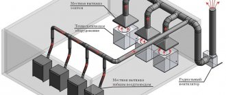
Location of ventilation ducts
It is easy to install the unit if the shaft is located directly behind the wall of the bathroom, even if it is combined with a toilet or is located next to the kitchen. If these two rooms are separated, then a channel design is required. It is installed on a shaft segment, at the junction of 2 air ducts.
Reasons for installing a fan
The main sign that indicates the need to install a fan in the ventilation duct is the appearance of condensation and, as a result, mold and mildew on various surfaces of the room. These pathogenic microorganisms can serve as a source of various types of infections that affect residents of an apartment or private country house. In addition, the premises of an apartment or house can be filled with odors from neighbors below or above. This also suggests that natural ventilation is not working well.
The use of a connection diagram for an extractor hood fan with a timer in the bathroom helps improve the sanitary environment of the room. When the device is turned on, the air mass circulates, which leads to the disappearance of unpleasant odors. On metal surfaces (again due to the high level of humidity), the appearance of new rust is stopped.
As for the proliferation of fungi, their growth also stops. In addition, damp deposits on tiles (and such material is present in the design of many bathrooms) and mirrors disappear.
There are different models of fans on sale, among which you can find modern devices that operate silently. In addition, they have a rather attractive design and compact size.
Tips for using home hoods
In order not to worry about how to repair the hood, you should follow simple rules:
- The hood should hang from the gas stove at a level of 80 cm and 70 cm from the electric hob. Otherwise, the device will become very hot and suffer damage. And if you hang it lower, the efficiency will suffer.
- When changing gears, it is better to start with a low speed so as not to put a sudden load on the engine.
- Do not start the appliance if the stove is empty, as the motor will also overheat.
- Change and clean filters. Otherwise, the engine becomes covered with grease, as well as the circuit board, lamps, and so on. This leads to overheating and breakdown.
- Install a protective relay to protect the device from power surges.
Wiring diagram in the bathroom for a fan with a timer
As you can see, you need to run a three-wire cable to the exhaust fan.
Now, knowing the connection diagram, you can proceed directly to installation.
How to fix a hood light?
Users often use hood lighting as an additional option. It's really convenient, and the LEDs provide good lighting.
If the light in the hood breaks, the procedure is as follows:
- Screw the light bulb into another fixture. Perhaps it has served its purpose and needs to be replaced.
- Turn on the fan to see if the system works at all. Works? Let's move on to point 3.
- Check the quality of the voltage in the sockets with an indicator screwdriver. Also check to see if the shield has been knocked out. If there are no faults, then inspect the cord, ring the backlight switch and other circuit elements. So, you will find a weak point, but usually the cause is a burnt out light bulb or a broken socket.
Option - delayed shutdown
This is an evolution of option 2, and quite significant. Let's look at the control units for the exhaust fan from Noolight (Belarus).
The BZT-300-SU unit is connected to a 230V power supply, an exhaust fan (to control it) and a bathroom lighting (to understand when it turns on). The timer turns on the fan 30 seconds after the lights are turned on and turns off the fan 5 minutes after the lights turn off. Not bad already. If we logged in for less than 30 seconds, then we won’t hear it. And 5 minutes of work will be enough for ventilation.
The BZT-300-SUF block is even cooler. There is no need to connect a lamp to it; it has a built-in photocell that will understand when the light turns on. And the turn-on delay and turn-off delay times are adjusted with knobs on the block, as is the sensitivity of the light sensor. The block costs about 500 rubles, but greatly adds comfort.
Motorized damper control behind the fan
A check valve is usually installed behind the hood fan. This is a simple mechanical thing that allows air to pass in one direction (into the mine) and not in the other (into the house). It looks something like this:
The picture shows that air will flow from right to left, lifting the curtains, but not from left to right. The goal is obvious - to prevent air from neighboring bathrooms and kitchens from reaching us.
At one of my sites (apartment), the customer stated that he did not trust mechanical valves, so it was necessary to install a damper with an electric drive, and it did not matter how much it would cost. This makes some sense, since from the picture above we see that air can theoretically flow from the ventilation shaft into the apartment through the cracks. This should not happen, since there is less air pressure in the ventilation shaft, but getting in is possible.
To prevent air from ever entering the apartment, we install a damper with a servo drive, like this:
When it is above, we turn the damper and open the air duct; when it is not necessary, we close it so that air does not flow. We can connect the damper drive in parallel with the exhaust fan and use a spring damper drive. This means that when there is no power, the damper is closed, but when power is supplied, the drive opens the damper. The spring returns the damper to the closed position when the actuator does not pull it open.
But there's a problem. Usually, when the fan is turned off, there is a small air flow from the bathroom to the ventilation shaft due to the difference in air pressure. If we apply a piece of paper to the switched off fan, it should be attracted. Due to this, a small passive air exchange is carried out, and the air does not stagnate in the bathroom, and indeed in the apartment in general. When the damper is closed, there is no air exchange at all. This means that we need to ensure that the exhaust fan is turned on periodically and the damper is opened.
For simplicity (although what simplicity can there really be) we use a programmable relay Aries PR. We install it in the shield and connect it according to the diagram:
We need to connect the bathroom lights and fans to the switchboard. And in the relay through the Owen Logic program we program the following:
- 60 seconds after turning on the light, turn on the exhaust fan. If the light turns off within 60 seconds after turning it on, then we do not turn on the fan - this condition was enough for me with Noolight blocks.
- 5 minutes after turning off the lights, turn off the exhaust fan.
- We turn on the exhaust fans automatically for 5 minutes every day at 10, 12, 14, 16, 18, 20 and 22 hours.
It would also be nice to make sure that the hood automatically turns on only if the light is not turned on during these two hours. But I'm not sure yet if this can be programmed through Owen Logic. Owen Logic operates with logical blocks such as AND, OR, NOT and more complex ones, so programming there is quite simple.
54, total, today
Related posts:
- What can be installed from a Smart Home Since not everyone understands what a modern…
- Air recuperator Marley MENV-180 PLUS If you are concerned about the supply of air from the street (which seems to be...
- Ventilator Mitsubishi Lossnay VL-50EU5 I’ll tell you about the ventilator (aka recuperator) that I chose myself...
- Control of light and hood in the bathroom, smart, but without a Smart House. There is no Smart House system in the apartment, there is no central controller...
- Ventilation control in a Smart Home Ventilation is an air exchange system between indoors and outdoors. She…
- Cable installation for a Smart Home As I already wrote, the most unreasonable way to save money in construction...
- Payback of the electrical and Smart Home project For me, all the advantages of preliminary implementation of the electrical, low-voltage and...
Installation stage
With the diagram for connecting a fan with a timer to the electrical line, everything is now more or less clear; now it’s time to get down to the installation procedure. However, an electrical cable must first be laid to this place. To do this, a groove is made from the distribution box.
Now it is clear why such work is planned to be done during scheduled repairs or during the construction stage. After this, you should connect the wires to the contacts on the fan (this has already been written in more detail above).
Before installing the fan, the decorative grille is removed from the shaft channel (if it has been cleaned, it is already open). If you chose the installation method using self-tapping screws, you should drill holes for the dowels, where they will then be screwed in during the installation of the fan. At this point, the dowels themselves should already be pre-inserted into the holes made.
If necessary (if it is not possible to fasten it with self-tapping screws), you can go the other way - attach the body of the exhaust device to a special glue or sealant. At the final stage, the removed decorative panel is returned to its place.
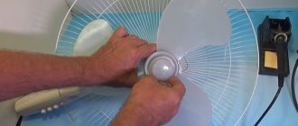
Fan disassembly: features of different types and disassembly instructions
Today we will look at the features, main malfunctions, process and algorithm for disassembling exhaust, duct and floor fans.
These devices are installed inside the exhaust openings. Most often, the exhaust mechanism fails due to the blown fuses located on the motor inside the fan. And for repair, the fuse must be replaced. To do this you need to get to the engine itself, located in the middle. For disassembly you only need a screwdriver.
The parsing algorithm is as follows:
- Remove the mechanism from the wall. Disassembling the device is quite a delicate job, so getting to the motor without removing the fan from the wall will be very difficult, plus there is the possibility of causing even more damage during disassembly.
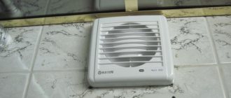
Bathroom fan assembled
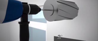
- Remove the protective plate. The front protective part is attached to the mechanism, most often with bolts, so removing it will not be difficult. You just need to choose the appropriate screwdriver.
- After removing the front plate, turn the fan over. It is necessary to remove the protective plate from the back. Unfortunately, the back side is most often soldered to the body, so it will have to be torn off. To assemble the mechanism, you must prepare “Moment” type glue.
- Remove the working unit with blades. This element is not attached to the body in any way, since it requires torsion. Therefore, it is very easy to remove it.
- Turn the device over. Remove engine protection. This is an ellipsoidal-shaped element located immediately behind the front plate. Unfortunately, it is also, most often, soldered to the body, so it also needs to be torn off and glued when reassembled.
- Remove the power cables. When the protection is removed, you can already see the target - the engine. Power cables pass from it through special holes and are connected to the rear of the case. These cables need to be removed through those same holes.
- Turn the mechanism over again. On the back side, in the place where the working blade element was, you can see several bolts (usually there are 2 of them). These bolts secure the engine to the housing. They need to be unscrewed, and the goal will be achieved.
Having reached the engine, you can find the same fuse next to the winding. It can be easily removed and replaced with a new one.
READ MORE: How to make a pond at your dacha with your own hands step by step: photos and decoration features
Connect directly to the junction box
Fans with a humidity or motion sensor allow you to make air exchange in the bathroom fully automated (they are in any case equipped with a timer). That is, the participation of the home owner is not necessary at all. Even in a simple connection diagram, a fan with a timer and a humidity sensor should not include the cheapest one. In addition, you should pay attention to another point if the bathroom is separate:
- Devices with a humidity level sensor - for the bathroom.
- Fans equipped with a motion sensor – for the toilet.
The first ones will be activated automatically, as soon as the humidity level exceeds the established limits. Moreover, the hood will work until it reaches the normal parameters.
As for models with motion sensors, they are turned on when a person appears in the range of the sensors. The fans will automatically turn off after the delay set on the timer.
And since the system is fully automated and operates without human intervention, switches are not included in its connection diagram as unnecessary. For this purpose, the wires from the distribution box (phase, neutral, ground) go directly to the fan contacts.
Preparing the hood for cleaning
How to clean grease from a hood?
Every housewife knows how quickly this type of equipment gets clogged and how difficult it can be to deal with a thick layer of fat. Before you begin cleaning procedures, you should read the user instructions, since the hood will have to be disassembled.
Here are some tips we recommend you take into account:
- Under no circumstances should you disassemble the device without unplugging it from the mains.
- Next, you need to remove the hood cover. Using the instructions and a detailed diagram for assembling/disassembling the device, find its latches.
- Keep in mind that the pipe that is the ductwork also needs regular cleaning. Some owners simply replace the corrugation with a new one, but this method does not work with all models of ventilation systems.
- Then it is necessary to thoroughly clean the filter and the unit body itself from grease deposits.
Connecting a bathroom timer
As an example of connection, we use the popular Granit-BZT-300-SU timer from the Nootekhnika company. It will work in tandem with an S&P Silent 100 exhaust fan.
The device itself is quite compact, you can see it in the image below. The maximum power of the fan connected to it should not exceed 300W.
As you can see, the timer has six contacts for connection, all of which are used during installation. And although it looks quite scary, there is nothing complicated here, especially if you understand the connection diagram.
How to fix the hood speed switch?
Here, the reason why the hood does not work is clear - the button in the control unit is broken.
What do we have to do:
- Remove the cover and inspect the button, the contact may have burned out.
- Check the tracks on the board.
- Ring the chain.
- And inspect the starting capacitor, it can also burn out over time. And then it must be replaced.
Natural ventilation analysis
However, before you start creating a forced ventilation system, it is worth analyzing the natural one. First you need to find the shaft hole and remove the decorative panel. Over the many years of operation of the building, usually no one looks here due to lack of need (according to the residents). Therefore, you can find not only deposits of garbage and dust there, but even cobwebs.
In accordance with SNiP, air exchange parameters in a standard bathroom should be 25 m3 per hour. Therefore, when designing it, it is difficult to do without a connection diagram for an exhaust fan with a timer. Of course, in the absence of special equipment, it is impossible to determine compliance with this standard. At the same time, you can use one folk method.
After the channel is put in order, it is worth bringing a lit match, candle or lighter to it. If the flame deviates towards the shaft, then the ventilation is functioning properly. And in this case, the decision to install a fan can be made for preventive purposes, or this measure can be abandoned for now.
If this technique is not enough for someone, you can use another one - using a sheet of paper. To do this, take a small piece and lean it against the ventilation shaft:
- the leaf is holding - everything is fine;
- a piece of paper fell to the floor - conclusions in favor of installing a fan.
The connection diagram for a fan with a timer in the bathroom will be implemented at its best if there is a flow of fresh air in the room. As a rule, its circulation is achieved through a small gap under the door. It is for this reason that a threshold is not installed in this room.
How to eliminate weak cravings?
Another well-known breakdown is why the hood doesn’t work, it doesn’t pull. What to do?
We are looking for the reason in filters that have not been cleaned or changed for a long time. And in a mesh that collects fat. If it is a filter, clean it or change it, depending on the type and period of use.
Poor draft also happens because a vacuum has formed in the room, since all the windows have been closed. Then the hood sucks in air poorly or stops doing so altogether. Just ventilate.
And there may be no draft in the home ventilation duct. Bring a lighter with an open flame to the ventilation. If the flame does not stretch towards the channel, forced ventilation is needed.
Connection diagram for a fan with a timer from a light bulb
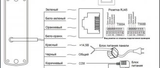
Exhaust fans with a timer are more expensive than conventional analogues without additional equipment. However, this is a good option for use in a bathroom. In this case, the connection diagram implies the presence of a switch and looks like this. Here you will need 4 wires:
- The phase wire goes to contact L directly from the junction box.
- Contact Lt - also for supplying the phase, only through the light switch.
- Terminal N - corresponds to zero; a wire also goes directly to it from the junction box.
- The PEN contact is a ground connection for connecting the corresponding conductor.
In other words, only the phase is opened, as is the case with lighting.
With this scheme for connecting a fan with a timer, the operating algorithm is as follows. Turning on occurs simultaneously with the lighting, and turning off occurs after a certain time after turning off the light (configurable on the device). That is, the fan will work even if the owner has already left the room. Usually this is a period from 5 to 30 minutes, which is quite enough for flow ventilation.
But there are other models on sale that are equipped with a reverse mode. In other words, the fan motor will only work when the light is turned off, that is, the opposite of the first option. And then after the time set by the timer has expired.
Cleaning the filter
So, it's time to solve the question: how to clean the hood filter? It is the filter that is the place of increased accumulation of dirt, dust and grease, as it protects the inside of the hood from contamination.
The filter looks like a multilayer grille with small cells, which are almost impossible to wash with bare hands. If the filter element is not very dirty, then cleaning it will not require much effort.
Just place it in a container of hot water and after a while treat it with detergent. Next, rinse the grille with running water and leave until completely dry.
If ordinary cleaning does not produce results, then you will have to use a more effective method - digestion. Select a suitable container, place filters in it and fill it with water.
The process can be repeated or the procedure time can be increased until the desired result is achieved. You should not often use alkaline preparations to combat pollution, as they can destroy the structure of the metal.
Option - even simpler
What could be even simpler than a hood switch? Turning on the hood along with the bathroom light. It makes sense in a frequently visited public toilet, where the fan does not disturb anyone with its operation. In an apartment, this means that, firstly, the fan will turn on and make noise every time, secondly, in most cases it will turn on when it is not needed, thirdly, turning off along with the light, it will not perform its function, that is, it will not have time to draw out the air so that it can be renewed from other rooms.
Sources
- https://mr-build.ru/ventilyatciya/tajmer-ventilyatora-sanuzla.html
- https://FB.ru/article/463323/shema-podklyucheniya-ventilyatora-s-taymerom-printsip-rabotyi-i-poryadok-soedineniya
- https://home-matic.ru/2017/06/umnoe-upravlenie-vytyazhkami-sanuzlov/
- https://rozetka-online.ru/podkljuchenie-i-ustanovka/item/144-podklyuchenie-tajmera-vytyazhnogo-ventilyatora-v-sanuzle
[collapse]
Installation of equipment
Household fans can be divided into 2 categories:
- wall;
- duct.
The wall mounted unit is placed directly in front of the vent outlet. If there is a need to move the device away from the hole (for example, when installing in a bathroom with a suspended ceiling), you can run an air duct to connect the fan and the shaft. The duct structure can be installed in the gap above the suspended ceiling.
The second type of fans can only be mounted inside the ventilation duct. They are usually used when carrying out work together with a suspended ceiling and are installed inside the air duct. Their body can be round or rectangular. You need to choose one that will match the shape of the air duct being installed. A diffuser is installed at the outlet. It can be used to regulate the air flow.
The height for mounting the device must be selected as high as possible. The top edge should be 50 mm below the ceiling. If the ventilation hole is located significantly lower, it is recommended to move it. Fastening is carried out using self-tapping screws or liquid nails. The choice depends on the weight of the device and the material of the walls.