You will again have problems with revs and jamming. Sometimes the cause of a breakdown is trivial and unpredictable.
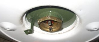
We've sorted out the rear bearing, then move on to the front part of the fan. There is a protective cap in the center here.
It unscrews, attention - clockwise, since the thread here is left-handed.
You throw it off and remove the propeller from the shaft. You now have access to the front journal bearing.
The principle is the same here. First, squeeze out and soften the old grease and dirt with a Vedashka, and then apply new one.
After that, put the propeller back on and close the lid. Having completed the repair, turn on the fan at high speeds, let it run for a few minutes, and switch to the speed required.
Short circuit of windings or broken wires
If the damage is more complex and simple lubrication does not help, you will have to disassemble the fan in more detail.
First, you do all the disassembly machinations as indicated above. After removing the propeller, unscrew the plastic front lock nut, which is located immediately behind it, and remove the entire protective frame.
In your hands you still have the motor itself and the leg in which the power wires pass and the push-button mechanism is located.
You disassemble this leg by unscrewing 6 screws.
First of all, check the soldering of the wires. It is quite possible that one of them, or even several, has fallen off or burned off.
If everything is intact, how can you figure out which wire goes where and is responsible for what? Start testing with two wires from the power plug.
One of them, let it be black (as in the photo below), goes directly through the backlight to the fan motor.
The second wire goes to the lower terminal of the dial switch (button 0).
Next, by pressing the corresponding buttons - 1st speed, 2nd, 3rd, certain switch contacts are closed, and thereby the engine speed changes.
Each wire from these buttons goes to its own terminal on the winding, with a greater or lesser number of turns. By applying voltage to them, you make the propeller spin faster or slower.
Floor fan connection diagram
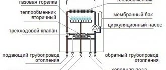
A simplified diagram of a wind blower looks like this.
Typical circuits for most inexpensive 3-speed floor fans are something like this:
Pressing each button is accompanied by the closure of its contact group.
In this case, the other contact group opens at this moment.
Sometimes these contacts burn out or do not reach their plate. Then you lose any of the speeds.
All this is checked simply with a Chinese multimeter, in circuit continuity mode.
If your very first wire breaks or there is no contact on it, the fan motor simply will not start. Therefore, if the fan is completely inoperative, check it first.
Unless, of course, before you make sure that the plug itself and the power cord from it are working properly. This is also caused by the tester.
Place one end of the probes on the pin of the plug, and touch the other end to the contact pad on the “0” button. If working properly, there should be zero resistance.
Then you can check the wires in the same way at all speeds. Contact probe for the plug - another probe for the outgoing wire from the corresponding speed button to the engine.
If there are zeros everywhere, then the switch and wires are working.
Next, check the second contact on the plug and the wiring that goes directly past the switch to the engine. Make sure your cord is intact here too.
Only after this can you proceed to checking the windings of the motor itself.
How to check fan windings
Set the resistance on the multimeter to 2000 ohms. Next, in order not to bite the wires anywhere, at the place where the capacitor is connected, strip off the insulation a little.
Look for the common point of the circuit, as in the diagram below.
Having found it, you call up the resistance of the winding. To do this, touch the contacts on the switch with the second probe one by one.
Approximate fan winding resistance values can be as follows:
Of course, they may differ slightly for different models, but the most important thing is that there is no breakage or short circuit. Measurements can show either several hundred Ohms or a little more than 1 kOhm.
It all depends on the power of the fan and the cross-section of the wire.
The resistance between the terminals of the windings will be lower - 100-200 Ohms.
The capacitor winding and the total resistance of all windings combined are also checked.
Here is the most competent and complete video on checking the performance of fan windings with a multimeter.
If checking the integrity of the windings also does not reveal any deviations or defects, move on. To do this, you completely disassemble the fan, as they say, piece by piece.
Engine disassembly and malfunction
First, the engine must be freed of all plastic parts. Unscrew the 4 screws from the front side and remove the cover.
On new models, in addition to screws, there are also latches. They need to be bent with a screwdriver.
To disconnect the leg, you need to find another screw, which is usually hidden under the plug.
Loosen it and pull out the mounting shaft. To dismantle the wires that pass through the leg, you will need to bite them out or unsolder them from the terminal blocks on the speed buttons.
At the same time, write down or sketch where each one is initially connected.
As a result, you should have a bare fan motor in your hands without anything unnecessary.
Let's take it apart. Unscrew the screws holding the back cover together.
At the same time, before disassembling, be sure to put marks on all covers and hardware indicating how everything was originally assembled.
Otherwise, after incorrect docking, you will lose alignment. There will be problems with the shaft wedging and the rotation of the blades.
Thermal safety relay malfunction
After removing the bearing, you get to the windings themselves. Among the bundle of power wires coming from the switch, look for a special thermal relay.
Very often the engine stops working after it burns out. This relay should operate and open the circuit at a winding temperature of 135-145 degrees.
After cooling, the relay closes again and the fan starts. So, sometimes it burns out completely and actually plays the role of a fuse.
If your fan often turns off and starts again on its own, this protection is to blame. Know that it doesn't just work. This means that your shaft is either jammed, or the windings are exhausted and they are overheating.
Overheating of the windings may be associated with the destruction of the small impeller, which is located on the shaft inside the engine itself. It is designed to blow air and reduce the temperature of the coils.
The cheapest models do not have a temperature sensor-relay; everything is connected directly. Based on this, if your “thermal fuse” has burned out, you can, of course, bypass it and start the wind blower. But at the same time you will be left without fire protection.
This relay is also checked by the tester.
There should be a chain between its legs in continuity mode.
Shaft displacement and broken turns
If all the parts and relays inside are intact, all that remains is to carefully examine the windings, shaft and rotor through a magnifying glass. You may see broken or damaged copper strands.
This happens when a bearing jumps out of its seat and the rotor begins to hit the windings.
With modern Chinese floor fans, the screw connection between the two halves of the motor quite often loosens. Do not forget that the shaft on both sides is mounted on self-centering copper-graphite bushings, which are tightly locked in the covers.
When assembling and tightening them, you can lightly tap the transformer iron itself with a hammer so that the shaft rotates easily, with little inertia. Someone tries to catch the center on their own and creates such a quiet horror.
Eventually the shaft falls out of the bearing, resulting in a wedge. As a result, the rotor begins to scratch the windings and its surface.
Also keep in mind that if your fan fell and then stopped working and rotating, then the bushings are most likely misaligned here too. Nothing else can break from such a fall.
This will not damage the capacitor, and the windings covered with varnish will not break. Perhaps some buttons may move away. But first of all, check the alignment of the bearings. And then everything will work as it should.
Unfortunately, you cannot cope with a mechanical defect in the windings or rotor, as well as their intra-turn short circuits. It is not rational to rewind the engines of cheap wind blowers; it will be much easier to buy a new model.
However, this is already the last stage of verification, and there is hope that you will never get to it, having found damage somewhere else using the methods discussed above.
Source
Share the news on social networks
- Related Posts
- How to crimp a tip without a tool - 3 easy ways
- Differences between SIP 5 and SIP 4 wires - all brands of SIP, difference in installation prices, characteristics
- Warm floors on the street - a whim or a necessity, mistakes, installation rules. Heating of steps, porch, connection of thermostat.
« Previous entry
Calculation of the capacitance and voltage of the working capacitor
The calculation comes down to selecting such a capacitance so that at a rated load a circular magnetic field is provided, since at a value below or above the rated value the magnetic field changes its shape to an elliptical one, and this worsens the performance characteristics of the engine and reduces the starting torque. Engineering reference books provide a formula for calculating the capacitance of a capacitor:
Average = Isinφ/2 πf U n 2
I and sinφ – current and phase shift between voltage and current in a circuit with a rotating magnetic field without a capacitor
f- AC frequency
U – supply voltage
n - winding transformation coefficient, defined as the ratio of winding turns with and without a capacitor.
The voltage across the capacitor is calculated using the formula
Uc= U√(1+n 2 )
Uc - operating voltage of the capacitor
U - motor supply voltage
n - winding transformation ratio
The formula shows that the operating voltage of the phase-shifting capacitor is higher than the motor supply voltage.
Calculation manuals give an approximate calculation - 70-80 µF of capacitor capacity per 1 kW of electric motor power, and the capacitor voltage rating for a 220 V network is usually set at 450 V.
Also, a starting capacitor is connected in parallel to the working capacitor for the start-up period, for about three seconds, after which the relay is activated and turns off the starting capacitor. Currently, circuits with an additional starting capacitor are not used in air conditioners.
More powerful air conditioners use compressors with three-phase asynchronous motors; starting and running capacitors are not required for such motors.
Electrical circuit of the fan
The electrical circuit of the fan consists of two parts - an electric motor with a starting capacitor and a unit for switching on and adjusting the speed of rotation of the blades.
The electric motor is a metal casing (stator) in which windings made of copper wire are fixed and connected according to the diagram shown above. A rotor is also fixed in the housing in sliding bearings, which, in response to the appearance of an electromagnetic field as it passes through the stator windings, rotates.
By applying supply voltage to the windings L1, L2 or L3 using interconnected switches S1, S2 and S3, you can regulate the air flow speed. The motor winding L4 and the capacitor C1 attached to the motor housing are used to start the motor.
If winding L4 or capacitor C1 is broken, the engine will not start when turned on in automatic mode. But if you turn the impeller clockwise by hand, the blades will begin to rotate. In this way, you can determine the malfunction of this chain.
In some fan models, to protect the windings from overheating in the event of a malfunction, a thermal fuse (indicated St° in the diagram) is installed at an operating temperature of about 125°C.
When heated above the design temperature, the thermal fuse breaks the circuit and the supply voltage is not supplied to the motor windings. This prevents them from burning out if the rotor jams when the lubricant is produced. The thermal fuse is usually installed at the end of the stator windings.
There are two types of thermal fuses - disposable and self-resetting. The latter, when heated above the temperature indicated on their body, break the circuit, and when they cool down, they close again. This avoids the need to replace them in the event of a jammed rotor.
How to disassemble a floor fan
From what has been said, it is clear: there is nothing to break inside the floor fan. This is a motor and a capacitor. The rest falls on the mechanical part, the gearbox. If there is whistling or noise, try lubricating the gears. How to do this is clear from what has been said. There are a couple of holes in the gearbox housing for these purposes. Solid oil is suitable for plastic parts.
Repairing a floor fan yourself shouldn't be too difficult. Replace the motor with one of suitable weight and size. The main types of breakdowns concern the mechanical part; restoration is carried out using conventional (welding plastic with polyethylene) methods with skilled hands.
Description of the machine
Single-phase electric motors are usually called asynchronous single-phase electrical machines with low power. The magnetic core of such machines has a two-phase winding, which is divided into a starting (starting) and a main winding. The need for 2 windings is as follows: they must cause the rotor of the electric propulsion (single-phase) to rotate. At the moment, such devices are conventionally divided into 2 categories:
- Presence of starting windings. In this embodiment, the starting winding is connected through a starting capacitor. When the start is complete and the machine has reached its rated rotation speed, the starting winding is disconnected from the power supply. After which the engine continues to rotate on the working winding connected to the network (the capacitor charges during startup and turns off the starting winding). The required capacitor volume is usually indicated by the machine manufacturer on a plate with all the parameters (as a standard it should be on all engines).
- Machines with working capacitors. In such electrical machines, the auxiliary windings are always connected through capacitors. In this case, the volume of capacitors is determined by the design of the engine. In this case, the capacitor remains switched on even when the machine reaches the nominal operating mode.
To correctly connect an electrical machine, you must be able to determine (or know) how the starting and operating windings are wired, as well as their characteristics.
It is worth noting: these windings differ in the conductors used (their cross-section), as well as in the turns. So, for the working windings, conductors of a larger cross-section are used, and they have a larger number of turns. It is important to know that the resistance of the working windings of different machines is always less than the resistance of the starting/auxiliary windings. In this case, measuring the resistance of the motor winding is not difficult, especially if special multimeters are used.
Based on what has been described, it is worth giving some examples.
Floor Fan Motor Speed Control Method
Nothing is said about the speed control method, which is not surprising. In the model considered, four wires come to the coils, one supplies a plug. The other three enter the winding through fabric cambrics. What is inside is not known for certain. The choice is small; an asynchronous motor with an insulated rotor is controlled in two ways:
- Change in voltage amplitude.
- Switching windings with an unequal number of turns.
We don’t take inverter control into account; in this case there is simply no room for such a complex circuit. What remains is regulation of the voltage amplitude. Each wire has an unequal number of turns. If one speed (two) fails, the cambrics will have to be cut, therefore, the electrical circuit of the engine will become obvious. A diligent master will wind a new coil, a lazy one will take money from the client to buy a new engine (the old one will be used for non-ferrous metal).
The number of turns is indirectly determined through the resistance ratios between the terminals of each speed. The tester uses a constant voltage to measure the quantity, so the inductive part of the impedance is eliminated from consideration. The number of turns is directly proportional to the ohmic resistance of the winding section.
Checking the fan motor
table fan Vitek
Let us consider in detail how the fan motor is checked. As an example, an electric motor corresponding to the version of household table fans is shown.
photo #1
The photograph shows a small electric motor \photo No. 1\ of a table fan. To present this topic more clearly, the explanation will be accompanied by personal photographs of diagnostics of the electric motor .
photo No. 2
Carrying out diagnostics of electrical connections begins with a preliminary check of the device itself \photo No. 2\.
Why is such a check necessary? — The check is carried out to ensure that the probe wires of the device do not have a break. That is, in practice, such a device malfunction often occurs as a broken wire in connection with the probe \ metal pin in connection with the wire \.
If there is a break,\ for a certain section of the electrical circuit\ the display of the Multimeter device shows “one”. If two probes of the device are short-circuited with each other \with the range of least resistance set, the display of the device will show a zero resistance value. For this example, this will mean that the device is working \functional\.
Connection
But then the parameters of the circuit elements, which depend on the power and connection diagram of the windings, will need to be changed, which is not very convenient to use. A model with a power of 3 kW will cost about 10 thousand. The connection is made according to this scheme. Connecting a three-phase motor according to a triangle diagram. Distribution box of a three-phase motor with the position of jumpers for connecting according to a triangle diagram. In the distribution box, the contacts are usually shifted - opposite C1 is not C4, but C6, opposite C2 - C4. To be able to operate an electric motor in a single-phase volt network, it is necessary to switch its winding to a triangle circuit first.
The value of the working capacitance of the capacitor is determined by the design of the engine.
They are called capacitors.
It is necessary that the rated voltage of the capacitor is equal to or greater than the calculated one.
However, capacitorless starting of a 3-phase motor from a single-phase network is possible thanks to the use of bidirectional switches that operate for short periods of time.
To exclude an interturn short circuit, a thermal relay is used, which, when a critical temperature is reached, turns off the additional winding. Not all three-phase electric motors are capable of working well in single-phase networks, but most of them cope with this task quite satisfactorily - except for the loss of power. Connecting a 3-phase motor to a 220V network via starting and running capacitors
Connection diagrams for single-phase asynchronous motors
With starting winding
To connect a motor with a starting winding, you will need a button in which one of the contacts opens after switching on. These opening contacts will need to be connected to the starting winding. In stores there is such a button - this is PNDS. Its middle contact closes for the holding time, and the two outer ones remain in a closed state.
Appearance of the PNVS button and the state of the contacts after the “start” button is released"
First, using measurements, we determine which winding is working and which is starting. Typically the output from the motor has three or four wires.
Consider the option with three wires. In this case, the two windings are already combined, that is, one of the wires is common. We take a tester and measure the resistance between all three pairs. The working one has the lowest resistance, the average value is the starting winding, and the highest is the common output (the resistance of two windings connected in series is measured).
If there are four pins, they ring in pairs. Find two pairs. The one with less resistance is the working one, the one with more resistance is the starting one. After this, we connect one wire from the starting and working windings, and bring out the common wire. A total of three wires remain (as in the first option):
- one from the working winding is working;
- from the starting winding;
- general.
We work further with these three wires - we use them to connect a single-phase motor.
With all these
- Connecting a single-phase motor with a starting winding via the PNVS button
connecting a single-phase motor
We connect all three wires to the button. It also has three contacts. Be sure to place the starting wire on the middle contact (which closes only during the start), the other two - on the outermost (arbitrary). We connect a power cable (from 220 V) to the extreme input contacts of the PVNS, connect the middle contact with a jumper to the working one (note! not to the common one). That's the whole circuit for switching on a single-phase motor with a starting winding (bifilar) through a button.
Condenser
When connecting a single-phase capacitor motor, there are options: there are three connection diagrams and all with capacitors. Without them, the engine hums, but does not start (if you connect it according to the diagram described above).
Connection diagrams for a single-phase capacitor motor
The first circuit - with a capacitor in the power supply circuit of the starting winding - starts well, but during operation the power it produces is far from rated, but much lower. The connection circuit with a capacitor in the connection circuit of the working winding gives the opposite effect: not very good performance at start-up, but good performance. Accordingly, the first circuit is used in devices with heavy starting (concrete mixers, for example), and with a working condenser - if good performance characteristics are needed.
Circuit with two capacitors
There is a third option for connecting a single-phase motor (asynchronous) - install both capacitors. It turns out something between the options described above. This scheme is implemented most often. It is in the picture above in the middle or in the photo below in more detail. When organizing this circuit, you also need a PNVS type button, which will connect the capacitor only during the start time, until the motor “accelerates”. Then two windings will remain connected, with the auxiliary winding through a capacitor.
Connecting a single-phase motor: circuit with two capacitors - working and starting
When implementing other circuits - with one capacitor - you will need a regular button, machine or toggle switch. Everything connects there simply.
Selection of capacitors
There is a rather complex formula by which you can calculate the required capacity accurately, but it is quite possible to get by with recommendations that are derived from many experiments:
- The working capacitor is taken at the rate of 70-80 uF per 1 kW of engine power;
- starting - 2-3 times more.
The operating voltage of these capacitors should be 1.5 times higher than the network voltage, that is, for a 220 volt network we take capacitors with an operating voltage of 330 V and higher. To make starting easier, look for a special capacitor for the starting circuit. They have the words Start or Starting in their markings, but you can also use regular ones.
CONNECTING A COMPUTER FAN TO A 220 V NETWORK
In the process of resuscitation and modernization of Solntsev’s amplifier, we had to get rid of the bulky power supply made on the TS-180 transformer. A switching power supply based on IR2153 with a power of 200 W was manufactured. However, during operation, with a removed power of about 130 W, heating of the pulse transformer was detected. Not critical, but still present. In addition, the stabilizers L7815 and L7915 heated up quite noticeably. The tight mounting on the board did not allow installing large radiators.
To eliminate this effect I decided to use a cooler. The choice settled on a small-sized fan with a power of 0.96 W with a power supply of 12 volts and a current consumption of 0.08 A. Since a transformer power supply for it would have unacceptable weight and dimensions, I decided to assemble a transformerless power supply with a quenching capacitor.
Post navigation
There are other schemes for connecting a motor through a capacitor, but we will consider these issues another time in another article.
Operating principle and startup scheme
Capacitors that are in a circuit can be charged. The required torque is provided by the displacement of phase currents in the windings of the IM. And in many cases, electrical equipment is driven by three-phase motors.
If you look at a plate where two currents are indicated through a fraction, it will be the smaller of them. The working capacitor is connected permanently in the winding circuit, the starting capacitor is closed briefly through the start switch. Installation and selection of components Capacitors have considerable dimensions, so they do not always fit into the inside of the boron junction box on the electric motor housing. It doesn’t make sense to immediately start calculating the connection diagram.
The capacity of the starting capacitor should be 2.5 - 3 times greater than the working capacitor. If the engine starts easily and has enough power to operate, then everything has been selected correctly. Everything is connected simply, it is fed into the thick wires. connecting a 380 to 220 volt motor
Fan troubleshooting and troubleshooting
To reduce costs and achieve low noise levels during operation, plain bearings are installed in fan motors. As a result, after a couple of years of operation, the lubricant is exhausted, and this is the most common cause of fan failures.
| Table of fan malfunctions and recommendations for their repair | |||
| External manifestation of the malfunction | Possible cause of malfunction | Troubleshooting | Repair method |
| The fan turns off after some time after normal operation and turns on again after a while | A self-resetting thermal fuse against overheating of the windings is triggered | Check the freedom of rotation of the impeller, disassemble the fan and inspect the stator windings for blackening | Lubricate the bearings, rewind the winding |
| The fan turns on, but the blades rotate slowly | The grease in the electric motor bearings has thickened or run out | If the bearings are insufficiently lubricated during operation, the fan produces increased acoustic noise and a burning smell may appear due to overheating of the motor windings | It is necessary to disassemble the fan and lubricate the sliding bearings with machine oil. |
| Mechanical wear of electric motor bearings due to lack of lubrication. In this case, vibration of the impeller relative to the center of rotation is often observed | Rock the impeller to the sides relative to the center. If the play is more than 0.5 mm, then the bearing is worn out | Replace the bearing with a new one | |
| The fan does not start, the blades do not rotate | The cord is not plugged into the outlet | Check | Insert the cord plug into the socket |
| No voltage at the socket | Check the presence of voltage in the outlet using a working electrical appliance | Connect the fan to a working outlet | |
| The power cord is faulty | Visually check the plug and cord for mechanical damage, check the integrity of the cord wires with a multimeter | If faulty, replace the power plug or cord | |
| The switch or speed switch is faulty. The battery in the remote control is low | It is necessary to open the Fan and test the switch with a multimeter. When in the on position, the resistance between the switch contacts should be zero | If the switch is faulty, replace it. If you don’t have it at hand, you can short-circuit the contacts of the switch and turn off the fan by removing the plug from the socket | |
| The fan hums and gets hot when turned on. | The rotor shaft is jammed due to depletion or thickening of the lubricant | Disassemble the fan, wash with solvent and lubricate the bearings | |
| The fan hums and gets hot when turned on. | Break in the starting winding or capacitor. | Turn the impeller by hand, if it rotates, then replace the capacitor or try to find the break point of the starting winding | |
| Broken rotor windings | Visually check the windings for mechanical damage and local darkening, check the integrity of the windings with a multimeter | If a break in the winding cannot be found by external inspection, then it will have to be rewinded, which is not economically feasible. | |
| The thermal fuse against overheating of the electric motor has tripped due to its malfunction | Check the integrity of the thermal fuse with a multimeter. Its resistance should be zero. To check in the absence of the device, you can temporarily short-circuit its terminals | If a broken thermal fuse is detected, replace it with a serviceable one. If the new thermal fuse blows again when the fan is running for a short time, then the electric motor is faulty | |
For reliable operation of the fan, it is recommended to disassemble it and lubricate the bearings with machine oil before each season of operation. But no one does this, including me. Usually, lubrication is done when the blades stop rotating or the fan begins to make a lot of noise.
Calculation of motor capacitor capacity
The winding with a smaller cross-section is the starting one. Such devices have a power factor greater than that of the short-circuited devices described above and develop greater torque in comparison with them. You can do this yourself or use online calculators. The circuit with a working capacitor does not provide for disconnecting the additional winding after starting and accelerating the engine.
If to connect an asynchronous motor you use not a three-phase network, but a household single-phase one, that is, power it through one winding, it will not work. Connecting capacitors (part 1)