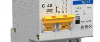
A differential circuit breaker is a switching device that combines a circuit breaker and a residual current device (RCD).
There is an opinion that a circuit with a differential circuit breaker without grounding is inappropriate. Electricians motivate this by the fact that the wiring is usually made in a two-wire standard, and the absence of a difavtomat will require expensive modernization. However, this opinion cannot be considered correct, since the machine has only a couple of contact connectors, and there is simply no room to install a grounding conductor. In addition, the operating principle of protective systems does not require grounding. Below we will talk about the nuances of the operation of protective devices and how to connect a difavtomat without grounding.
Application of a differential machine
The difference between a residual current device and a circuit breaker is its functional purpose. An RCD is a switching device that protects a person from direct or indirect electric shock.
The residual current device monitors the current characteristics of the electrical wiring and, in case of any problems, turns it off. The RCD does not protect wiring from short circuits and overloads. Moreover, the device itself needs protection from these factors. For this purpose, a circuit breaker is placed in front of the residual current device.
The differential machine is equipped with an automatic switch, and therefore is considered a more technologically advanced device. The difavtomat is used to protect the electrical network from short circuits and overloads, when current leaks occur as a result of damage to wiring and electrical installations. The difavtomat protects a person when exposed to voltage.
Current leakage is understood as an unauthorized change in the route of current flow. When there is a leak, the electric current is directed not through the wiring or electrical installation, but through other metal objects. This happens when the insulating layer of the conductor is damaged or electrical appliances fail. As a result, a protective device is turned on, de-energizing the electrical network in the room.
Note! Current-carrying parts of the socket shorted by a person are not identified by the differential device as current leakage. The switch will react to such a situation as to a standard load, the current will not be cut off, and the person will come under voltage.
A protective device is especially necessary where there is an increased risk of electric shock. These include the kitchen and bathroom, where, due to the functional purpose of these rooms, a lot of electrical equipment is installed and high humidity is observed.
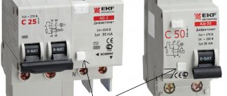
The machine does not have a third terminal for connecting the grounding conductor. It follows from this that the differential switch is suitable specifically for two-wire circuits.
So, the question of whether a differential device will work in a two-wire circuit has been answered: it certainly will. This fact is confirmed by many electricians: the difavtomat works properly in a three-wire circuit even if the grounding system is damaged.
Electric Shock Protection
Before answering the main question, why grounding is needed , you need to understand the design. A ground wire is a piece of electrical wire of a certain size, where one end is connected to electrical equipment and the other is run underground.
And it is the installation of a grounding device that makes it possible to prevent electric shock or minimize its impact on a person. The question also often arises: why is a grounding loop required? It is needed for household electrical equipment made of metal, this can be:
When inducing potential onto a metal body, the current must necessarily go into the ground. But in this case, it is necessary to create a device in the form of a metal structure that creates contact directly with the ground.
Thus, when a potential is applied to the electrical body of a household appliance, the electric current will completely go into the ground, and such a situation does not pose any danger to a person. Of course, some will still pass through the human body, but again, the situation is safe and there will be no harmful effects.
Operation of a difavtomat in a two-wire circuit
The operating principle of a differential device is reminiscent of an analyzer that compares the indicators of currents flowing through the phase and neutral conductors. If deviations in values occur due to a leak (for example, after a short circuit to the refrigerator body), the relay contacts of the difavtomat open and the network is de-energized.
As an example, let’s look at a situation where the insulating layer of the electrical wiring in a washing machine was damaged. Touching a bare current-carrying conductor to a metal casing causes current to spread where it should not exist. As soon as a person touches the washing machine, he will get an electric shock. Moreover, the victim will remain under tension as long as he touches the body (and it is difficult to tear himself away from it). In such a situation, an RCD or automatic circuit breaker comes to the rescue, turning off the current in the circuit.
How does a centrifugal pump with an electric motor work?
The diagram below shows the structure of the internal part of a centrifugal pump and its connection to an electric motor. In the body, pos. 1, which has the shape of a snail, contains an impeller, and blades are located on it. These elements are located on the motor shaft. The suction and pressure pipelines are connected to the discharge and inlet openings. The water that fills the pump, under the action of the centrifugal force arising from the rotation of the impeller by its blades, is thrown into the pressure pipeline from the housing. When the impeller rotates, a vacuum is created in the suction pipe of the device, due to which water continuously flows into the suction pipe.
Tip: Centrifugal pumps can only operate when the impeller, and therefore the suction pipe, is filled with water. Therefore, to retain water inside the pump when it is stopped, a receiving device having a check valve must be installed at the suction end of the pipeline.
If an electric centrifugal pump is put into operation for the first time after completion of installation work or repairs, it is necessary to first fill its housing with water. In this case, you need to ensure that there are no air pockets. The main indicators of pump operation are:
- Performance.
- Pressure
When choosing centrifugal pumps with an electric motor, you need to pay attention that its performance must correspond to the hourly flow rate of liquid in the system, and the pressure must be sufficient to raise the water to the required height and be able to overcome the resistance of pipelines and fittings.
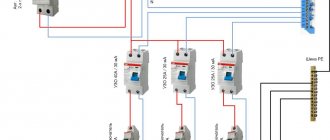
Methods for connecting an RCD without grounding
The RCD is not equipped with automatic equipment that would protect the circuit breaker from network overloads. In this regard, it is also necessary to include circuit breakers that react to shutdown during overload.
It is recommended to select the power of the differential switch slightly less than the power of the machine built into the same circuit with it. The approach allows you to avoid burnout of the protective shutdown device, since when the electrical circuit is overloaded, the machine does not turn on immediately, but after a certain time. If the power of the RCD corresponded to the machine, the differential switch would inevitably burn out.
There are two connection options:
- Installation of a single protective shutdown device for the entire building. As a result, all electrical appliances in the house are protected. The disadvantage of this method is that it is difficult to determine the cause of the malfunction. You will have to check all the electrical appliances in the house one by one. Another problem is the shutdown of the entire electrical circuit, despite the fact that the leak occurred in only one area. Losing power to the entire house leads to loss of computer data, breakdown of air conditioners and other household appliances.
- Installing a dedicated device (but lower power) for each of the potentially unsafe lines (bathroom, kitchen, garage, basement). In this case, you need to find much more free space in the shield. In addition, purchasing several devices will entail increased financial costs. The reliability of the protection increases, and the cause of the shutdown will be much easier to find (you will need to inspect 1 - 2 outlets, and not all those in the house).
A little theory
To increase performance, the design of the pump can be changed.
Structural diagram of parallel connection of pump wheels
With a parallel connection, each impeller delivers only part of the total flow, creating a full head, the flow in the pump is divided into a number of parallel jets. Such pumps are called multi-flow.
When entering the pump, the flow is divided into two parts and enters the impeller from both sides. The impeller in this case is a combination in one part of two impellers located symmetrically relative to the plane normal to the axis of the pump. When leaving the impeller, both parts of the flow are reconnected and enter the spiral outlet.
The design of such a pump is very compact.
Structural diagram of a series connection of pump wheels
With a series connection, each impeller produces only a portion of the total head at full flow, the pump head increases in steps.
This type of design allows you to increase the pump pressure as many times as it has stages. All wheels are mounted on a common shaft and form a single pump rotor.
The axial pressure balancing system, bearings, and seals are combined in one housing common to all stages, which makes the pump compact, reduces weight and reduces cost.
Diagram of a deep and submersible pump
A connection diagram for a submersible pump is needed to see in what order all the parts are connected.
The first step is to determine the depth of the well. The depth of the well is determined by the depth of groundwater. It must be remembered that the distance from the bottom of the well to the pump must be at least 1 meter. The distance from the top point of groundwater to the surface of the earth is called the dynamic level.
To ensure uninterrupted all-season use of the well, a special well - a caisson - is equipped. The depth of the caisson must be no less than the depth of soil freezing.
1. The pipe coming out of the well into the caisson is trimmed and connected to a pipe laid in a trench leading to the house. Thus, the pipeline located in the trench leading to the house must be located at a depth no less than the depth of soil freezing - i.e. at the level of the lower boundary of the caisson. It is recommended to lay two pipes in this trench: the first is for water supply, the second is for electrical wiring.
A coarse filter must be installed directly in front of the pressure control unit and the hydraulic accumulator. Additionally, the same filter is installed at the outlet of the hydraulic accumulator before supplying water to the pipeline system of the house, but this requirement is advisory in nature.
2. Next, you need to connect the power supply to the pump. The wires are connected according to the electrical diagram for connecting the pump. The pump control panel is installed in the boiler room of the house.
Electrical diagram for connecting the pump
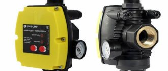
Connecting the pump directly to the power supply risks rapid breakdown of the centrifugal unit, and the main reason is that the pump will continue to idle even when the water level drops. For household water supply systems, the correct option is to include factory automation units in the water supply scheme. Such units are called pump control stations or hydraulic controllers.
Installing the device in a two-wire network
It is recommended to entrust this important work to a qualified electrician. If such an opportunity is not available, but you have at least minimal knowledge in electrical engineering, it is recommended to adhere to a number of rules:
- The power of the differential switch should be one step less than the power of the RCD. For example, for a 40A/30mA residual current device (the latter indicator indicates the leakage current), a 25 Ampere switch is required.
- If the wiring of the electrical circuit is complex, the amount of current leakage can be significantly more than 30 mA. The consequence of this will be frequent false alarms of the protective shutdown device. This course of events is avoided by dividing the total network load into two independent RCDs. Moreover, each of them can withstand a leakage of 30 mA, and this should be enough.
- In the electrical circuit of the bathroom you will need a differential switch with an operating threshold of 10 mA. For the bathroom, a 25A/10 mA RCD is recommended.
- According to the regulations, it is not allowed to install a differential switch upstream of the meter. According to his instructions, the inspector of the energy sales organization will force you to dismantle the device to prevent the receipt of electricity bypassing the meter.
- In addition to the residual current device for sockets, a 16 Ampere circuit breaker is installed.
- A 10 Amp RCD is installed to the differential switch for light switches in the house.
- It is recommended to install not a single-pole, but a two-pole device. This ensures greater security of the system, since it allows you to open not only the phase, but also the zero when the network is overloaded.
- When connecting a residual current device, you should strictly follow the instructions located on the device body.
- The differential machine is installed in a place inaccessible to random persons. However, if necessary, the machine must have free and quick access by specialists.
When all residual current devices are installed in place, their functionality is checked. The main task is to check the system for false positives. To check, connect the machine located in front of the device, the differential switch. Next, press the “Test” button on the device. If this is followed by a shutdown, the device is operating correctly.
Note! According to the standards of the PUE (Electrical Installation Rules), the installation of residual current devices in the networks of the TN-C subsystem is not permitted. If it is necessary to protect the electrical receiver, the grounding PE conductor is connected to the PEN conductor. Thus, TN-C is transformed into the TN-CS subsystem.
Boost pump STI CRP 15/9
Boost pumps STI
designed to increase pressure in an existing water supply system. Used in the water supply network to increase water pressure in the shower or at other water supply points, in front of water heaters (gas water heaters, instantaneous water heaters, double-circuit boilers), washing machines and dishwashers
Connecting RCDs to sockets
If a TN-C subsystem is installed, the device body is in some cases connected to zero. The connection diagram for the residual current device without grounding for sockets is designed for connection to the third side terminal. In this case, after an insulation breakdown, the current from the housing will be directed through the specified terminal. Contact is provided at the entrance to the house or apartment.
However, it should be noted that the implementation of the technique increases the likelihood of getting under voltage. If voltage reaches the neutral in the external network, current will flow into the housings of grounded electrical installations. Another disadvantage of this connection method is the regular operation of the circuit breaker when connecting loads.
You cannot connect in this way yourself. You will need to order a project that will include changes to the power supply system.
The following adjustments are expected:
- introduction of a three-wire network (instead of a two-wire one);
- abandonment of the in-house four-wire electrical network in favor of a five-wire one;
- separation of PEN conductor in an electrical installation.
The principle of calculating the resistance of grounding conductors
There are quite a few ways to calculate the characteristics of the main grounding elements, but the main parameter for such calculations is the same - the resistance indicator. Its optimal value is determined using data from the normative regulation of the PUE. It is impossible to implement reliable protective grounding of an object without calculating the resistance of its main elements.
For example, it is necessary to determine the grounding resistance for electrical equipment with voltages over 1 kW, with an isolated neutral. In accordance with the profile data of the documentation PUE 1.7.96, it is necessary to use the formula R≤250/I, where:
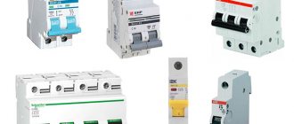
RCD selection
The circuit breaker is designed to operate with an overload for seconds or even minutes. The protective connection device is not able to withstand such loads and will most likely fail. Small power devices are used with a current of 10 Amps or less. For powerful devices you will need a reserve of 40 Amps.
If the voltage in the living room is 220 Volts, buy a two-pole device. For 380 Volts, a four-pole device is required.
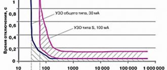
The leakage current indicator of the residual current device determines which device is needed: fire protection or current protection. The devices are capable of operating at different speeds. For fast response, selective devices are used, which come in two classes (S and G). Devices marked with the letter G have the highest response speed.
The machines are available in electronic or electromechanical versions. For electromechanical devices there is no need for additional power supply.
As for the type of leakage current, information about this is indicated on the housing. AC stands for alternating current, and A indicates both alternating and direct current.
Do voltage stabilizers and UPSs need to be grounded?
When creating a system of high-quality and uninterrupted power supply for household electrical appliances, it is important to remember that voltage stabilizers and UPSs, like other Class I electrical appliances, require grounding, such as this:
- will protect the user from electric shock upon contact with the metal casing of the stabilizer/UPS and equipment powered from it;
- will protect against leakage currents coming from the stabilizer network filters (they can leak to grounding).
Features of connection in a private house
The electrical network in a country house is not fundamentally different from that in an apartment, but more diverse options are appearing. For example, it is easier to install one single device at the input or several residual current devices on the most important lines of the network.
The 300mA input device protects all electrical wiring from fire. The RCD is capable of responding to the total leakage current from all existing lines, despite the fact that the standard is observed in each individual case.
Universal devices designed to operate at 30 mA are installed after fire protection devices. The next lines are the bathroom and children's room (Iу indicator = 10mA).
Conversion of the grounding system to TN-CS is allowed. Independent connection of re-grounding to the neutral is not allowed. If voltage gets to the neutral wire from the external network, grounding will become the only one for the surrounding houses, which, if the work is done poorly, becomes a frequent cause of fires. It is recommended to perform repeated grounding at the input site from the overhead power line.
The connection diagram for a residual current device in a small country house is usually the simplest, since the loads are relatively small. Most often, connection to a single-phase network and a 30mA device are selected. The device is universal and allows you to protect yourself from both fire and voltage.
In country houses, a main input and two circuit breakers are installed (for sockets and light switches). The boiler is connected to the network using an outlet or a dedicated machine.
Grounding switches
1.Natural
- water pipes laid in the ground (HW)
- metal building structures and foundations securely connected to the ground
- metal cable sheaths
— casing pipes for artesian wells
— gas pipelines and pipelines with flammable liquids
— aluminum shells of underground cables
— pipes of heating mains and hot water supply
The connection to the natural ground electrode must be in at least two different places.
Artificial
Contour
Remote: group and single
Allows you to choose a place with minimal soil resistance.
Traditionally, for artificial grounding conductors, angle steel with a flange thickness of at least 4 mm, steel strips with a thickness of at least 4 mm, or bar steel with a diameter of 10 mm or more are used.
Recently, deep-seated grounding electrodes with copper-plated or galvanized electrodes have become widespread, which are significantly superior to traditional methods in terms of durability and cost of manufacturing the grounding electrode.
A special problem is the creation of high-quality grounding in permafrost conditions. Here it is worth paying attention to electrolytic grounding systems that can effectively solve the problem.
Detailed information about various sealing schemes, calculation methods and consultations can be obtained on the website www.zandz.ru
Frequent connection errors
Incorrect actions when installing an RCD lead to unpleasant consequences: the device trips even without current leakage in the electrical circuit and normal load. Another situation is dangerous when operation does not occur in the presence of current leakage.
The most common mistakes when carrying out electrical installation work:
- After the differential machine there is a grounding connection with a neutral wire. For example, the neutral is combined with an open section of an electrical installation or with the neutral of a protection conductor. To avoid this gross error, you need to use the phase and zero of one specific switch. This will make it possible to avoid connecting the phase and neutral conductors through the protective system with other phase and neutral conductors.
- Single-phase connection of protection. The problem is that the load is not connected correctly to the working neutral switch. The current flowing through the load is differential for the residual current device. This leads to false alarms of the RCD.
- Twisted grounding and neutral conductor in a socket. The consequence of this is a false alarm when one of the electrical appliances is turned on. The load is connected to a circuit that is not within the area of responsibility of the RCD. In other words, the current is directed through the jumper.
- Connection of a pair of differential switches with twisted neutral wires. As a result of such an error, a differentiated current flows through both devices and one or two RCDs are triggered without real need.
- Several RCDs with incorrectly connected zeros were installed. The consequence of this is the simultaneous operation of differential devices.
- Incorrect connection of phase and neutral in the presence of several RCDs and different differential switches. For example, the load is connected to a zero, which is supposed to protect another electrical circuit. The result of the error is false positives of one or both systems.
- Polarity violation when making a connection: the phase goes to zero, and the neutral conductor goes to the phase conductor. As a result, the differential switch does not operate, since the currents flow in one direction. This leads to a lack of mutual compensation of magnetic currents. The incoming phase must be directed to the terminal marked with the letter L, and the incoming zero must be connected to the terminal marked as N. The upper terminals in the device are incoming, and the lower terminals are outgoing.
Appendix: project in DWG and PDF formats
Files in DWG and PDF formats are available for downloading only to authorized users.
Do you need to complete a grounding and lightning protection project? Order it by contacting the ZANDZ.ru Technical Center!
Still have questions about this calculation? Ask it in the comments to this page!
FC - controls
Vesper converters are equipped with a panel with an information LCD display and a set for control and commissioning. Depending on the inverter model, the displays may differ in the number of lines. The device display can display data on the current state of the parameters.
For greater convenience and the implementation of more complex control systems, you can connect an external remote control via analog and discrete (relay, transistor) outputs. And through the interface communication line - a PC (laptop or desktop).
The laptop can be used in oscilloscope mode to monitor changes in parameter values in real time. In this case, it is also necessary to prepare a place with an insulated surface in advance and provide for the possibility of running the laptop on battery power.