Well sources for obtaining clean water belong to the category of individual water supply. To do this, you need to connect surface or submersible electric pumps. They turn off when the main line is full, because the equipment cannot work without interruptions. To do this, connect automation, which is responsible for controlling the shutdown and on cycles.
Automation for the pump maintains normal operation of the system.
Choosing automation for the pump
- Peculiarities
- Kinds
- 1st generation
- 2nd generation
- 3rd generation
- Connection diagram
- Installation and connection of a submersible pump and automation
- Installation and connection of a surface pump with automation
- Manufacturers
- Adviсe
A water well is almost mandatory on the site; it provides many benefits. To ensure that its work is not marred by constant breakdowns, it is necessary to install automation. It can be different in layout, it can be purely mechanical or have an electronic control unit, but any automation ensures the correct operation of the pumping system.
Installation of a surface electric pump
If the well is no more than 8 meters deep, you can use a vortex surface pump or a pumping station.
The room for installation of equipment must be dry and provide an air temperature above 0 °C.
It must be taken into account that the device creates noise during operation.
The pump housing should be secured to the base with bolts and vibration-damping gaskets. A water supply from a well with an installed check valve and filter is connected to the inlet. The working line is connected to the output. The connections are sealed with a special thread, tape or flax.
Fill water through the filler plug, check the pressure in the accumulator, and turn on the power.
Peculiarities
Automation for the pump, as for heating, maintains the normal operation of the system, monitoring many parameters, for example, pressure, temperature of the pump, distributes water in the system, and the like. For correct operation, several units of various types are required and their adjustment to specific specifications, from the type of pumping equipment and well depth to the number of water intake points and the required operating pressure.
The normal operation of the pump is supported by the operation of the automation of important components.
- Distributing collector device. Provides water supply to several water intake points throughout the serviced area.
- Relay . Controls the starting and stopping of the pump. Necessary to control optimal pressure in the system. When sold, it has basic settings from the manufacturer, which can be changed according to the needs of a particular system.
- Pressure gauge , a device that measures the operating pressure of a system.
- Dry running sensor. Necessary to prevent overheating of pumping equipment in the absence of water in the system.
The minimum amount of automation for a pumping station includes a controller and a protection system.
- Controller that regulates pump power. Necessary for the system to operate optimally.
- Protection system: dry running sensor;
- sensor protecting against overheating;
- sensor that detects a break in the pressure line.
You can note the positive and negative aspects when using automation.
Automation, like any complex device, is designed to improve the performance of a mechanical component, in this case a pump, and therefore its use provides certain advantages, these include:
- a wide selection of specialized units allows you to select the appropriate option for a pump with almost any parameters;
- the automation set is already assembled into the system and is ready for operation, so you don’t have to select individual components or check parts for compatibility and synchronization of interaction;
- The main advantage of automation is that the entire pumping system operates in a smooth, measured mode, and there is no need to monitor its balancing, because this is also the task of the automation.
In addition to its positive qualities, automation also has its disadvantages, and these are:
- the assembled system is more expensive than assembling it from individual components yourself;
- if you have certain knowledge, you can select each component so that it ideally meets the requirements of the pumping system and configure it for optimal operation; With a ready-made system, such a complete match is rare, but if you look, you can find a good option with a high match;
- automation for the most part does not combine well with vibration pumps due to their specific requirement for an input pressure of 0.3 atm, for which it is not designed.
Reasons for decreasing pressure in the system and how to increase water pressure in the pumping station
Situations when the water pressure in a pumping station does not meet the requirements are quite common. Do not rush to adjust the operation of the automatic water pump. To solve problems, you should first carry out the following diagnostics:
Water pressure is affected not only by automation, but also by the condition of the filters, air pressure in the system, and the tightness of the suction pipeline.
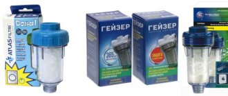
- Check the condition of the filters. Impurities of sand, clay and other elements can not only clog filters, but also cause corrosion of system elements, which will certainly affect the efficiency of the pump.
- Measure the air pressure in the system. Its reduction also affects the full functioning of the station.
- Make sure the suction pipe is tight.
If, as a result of the above actions, no problems are identified, it is necessary to intervene in the operation of the automation: check the condition of the hydraulic accumulator and set the pressure switch for the well pump. Quite often a mistake is made in which a high level of lower pressure is set. The station practically does not turn off in this mode, which, naturally, has a detrimental effect on its functioning.
Low pressure can also be caused by damage to the membrane or microcracks in the tank. Sometimes it is impossible to eliminate defects; a complete replacement of the hydraulic accumulator is required.
The water pressure in the system is easily regulated automatically.
Description of automation for the pump
Automation of pumping stations or the addition of automation to a standard pump ensures uninterrupted operation of the equipment. In this way, it is possible to optimize energy consumption.
Automation for the pump includes a relay, pressure gauge, sensor and distribution device
For a home well, the automation must contain:
- Distributing device. This collector device is designed to supply water to the site or to the house (to the required water intake points).
- Relay. Ensures that the pump starts and also stops the equipment. This element of the system is responsible for optimizing pressure. Often, relays are sold with ready-made settings, but reconfiguring the parameters yourself is not difficult.
- Pressure gauge. The measuring device is designed to control pressure. It can be electronic or mechanical.
- Sensor that measures dry running.
Special nodes must be present.
There is a block that provides equipment regulation. Thanks to this element, it is possible to create suitable conditions for the functioning of the entire product.
A protective system is provided to prevent dry running and overheating. In addition, there is a sensor responsible for the pressure break.
Setting and adjusting pressure
To independently configure the relay in question, you do not need to have any special knowledge of plumbing. It will take quite a long time to figure out how to cover a house with siding or install SIP panels according to the rules. There are much more nuances of work there. With the adjustment of the pressure switch of the pumping station, everything is much simpler. You just need to perform five actions in sequence.
To set up the water pressure switch you need to:
Turn off the power to the pump, and then drain the water from the cold water pipeline.
Turn on the hydraulic pump and record the pressure gauge readings when the relay turns off (this is the value of the lower threshold set by the large spring).
Open the water tap farthest from the pumping station and monitor the numbers on the pressure gauge when the pump turns on again (this is the upper threshold, adjusted by a small spring).
If the pressure in the open tap when starting the hydraulic pump was too low, then you need to increase the shut-off pressure by tightening the nut on a large spring. If the pressure is too strong, on the contrary, it should be slightly weakened.
Using a small spring, the delta between the upper and lower thresholds is set within 1.5–2 atmospheres.
We measure the pressure gauge and adjust the relay nuts
To complete the adjustment of the pressure switch, water is completely drained from the system again, and then the station is connected to the network. If everything is configured correctly, then the pressure in the taps should be satisfactory. Everything is extremely simple. The choice of building materials for the house and the planning of a rectangular plot of 15 acres will take a lot of time. Setting up the pressure switch is done in literally half an hour.
Watch the video about adjustment
Device characteristics
Through automation, it is possible to ensure the protection of electrical equipment, as well as extend the service life of the entire device.
You can view the characteristics of the device on the Internet.
Automation of a submersible pump has a number of advantages:
- There are many types of these devices designed for downhole equipment. When choosing a product, you should give preference to a model that is ideally compatible with the pump used.
- Finished units are sold with configured components. There is no need to look for components yourself and then assemble them into a single unit.
- Automatic operating systems are characterized by the safe activation of pumping equipment and regulation of its power. With the help of such a system, there is no need to constantly monitor the operation of the equipment.
In addition to these positive characteristics, such devices have several disadvantages. So, the finished system will be expensive. To save money but ensure high-quality control of the submersible pump, you can independently select the required components.
The automation unit should be used with a hydraulic accumulator. But such a device will have to be purchased separately.
If you plan to use a vibration pump, you will need to change the settings. Input pressure indicators should not exceed 0.3 atm.
Automation Gileks - operating principle.
Gilex automation starts the electric pump within 20-25 seconds after connecting to the power supply. Subsequent starts of the electric pump occur when the starting pressure is reached (pressure drop under the action of an open tap).
Unlike the CRAB system (a system with a pressure switch-tank), the condition for stopping the electric pump is not dictated by reaching a certain pressure in the system, but is determined by a decrease in flow to a minimum value.
When the automation unit detects such a condition, it stops the electric pump with a delay of 7 to 15 seconds. The interval of 7-15 seconds is set to reduce the frequency of operation of the electric pump in conditions of low water flow.
Technical characteristics of the automation unit:
Voltage – 220 – 240 V; Maximum current – 10 A; Starting pressure – 1.5 – 3.5 atm; Maximum water flow – 80 l/min; The maximum permissible pressure is 10 atm; The maximum water temperature is 60 °C.
Connecting Gilex automation.
When installing the Gilex automation unit, make sure that a pressure gauge is installed on one of its two sides. The pressure gauge is mounted using an O-ring and two mounting screws.
Select the location of the pressure gauge that is most convenient for you, plug the hole on the opposite side using a screw without using any seal.
Install the Gilex automation device in any place located between the pump supply and the first water collection point (tap).
The Gilex automation unit must be mounted in such a way that the inlet hole (1-inch thread) is connected to the direction of water flow exiting the pump, and the side outlet hole (1-inch external thread) corresponds to the direction of water flow in the pipeline.
Check the tightness of all connections.
Gilex automation for the pump is designed for pressures up to 10 bar. When using a pump with a maximum pressure of more than 10 bar, it is necessary to install a pressure reducer at the inlet to the automation unit.
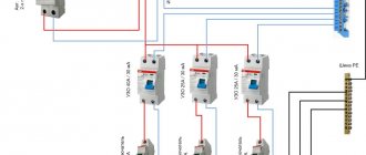
The electrical connection of the Gilex automation must be carried out following the diagram of the circuit board located on the casing (this wiring diagram for the Gilex automation is shown in the figure next to it).
When using a Gilex automation unit with three-phase or single-phase electric pumps with a switching current of more than 10 A, an electromagnetic starter should be used.
It is necessary to use an electrical cable with a thermal resistance of at least 99 °C.
The starting pressure at which the Gilex automatic pump is turned on is 1.5 atm. This pressure is considered optimal for most applications.
The starting pressure value can be changed using the adjusting screw located on the top of the automation unit marked + or -.
According to the standards, the starting pressure should be 0.2 atm more than the minimum required pressure in the system, and the pressure created by the electric pump should be 0.8 atm. more than the starting pressure of the Gilex 9001 automation unit.
Example 1.
The required pressure in the system is 2 atm, then the starting pressure is 2.2 atm, and the minimum pressure created by the pump is 3 atm.
Example 2.
The required pressure in the system is 2.6 atm, then the starting pressure is 2.8 atm, and the minimum pressure created by the pump is 3.6 atm.
Adjustment of Gilex automatics according to the starting pressure value is carried out in the following cases:
the vertical distance between the automation unit and the first water intake point (tap) exceeds 15 meters of water column (the maximum height of water rise is 30 meters) if pumps are used under load, i.e. in the case where the load pressure (pump head) is added to the pump pressure. The maximum pressure should not exceed 10 bar.
Starting and adjusting the Gilex 9001 automation unit.
Before starting the pump, make sure there is water in the pipeline. If the level of water being filled is lower than the level at which the pump is located, it is necessary to install a check valve on the suction pipe. To prevent overheating and pump breakdown due to dry operation (not a warranty case).
Before starting, fill the pipeline and working chamber of the pump with water.
Start the pump by supplying power to the Gilex automation unit (“NETWORK”). After stopping the pump, open the valve located at the highest point of your piping system.
The installation is considered correct if the pump runs continuously and there is a regular flow of water at the outlet of the tap.
If there is no water flow, you can extend the operation of the electric pump by holding down the “RESET” button for a period of time exceeding the timing of the automation unit.
If even in this case there is no water flow, it is necessary to turn off the power to the electric pump and repeat the installation procedure from the beginning.
The “PROTECTION” indicator is activated when the electric pump is turned off and indicates the danger of dry running. After you make sure that the suction line is filled with water, start the electric pump by pressing the “RESET” button.
Malfunctions and repairs.
Like any technically complex equipment, Gilex automation can fail in case of improper operation or incorrect installation. Below we present the most common problems and malfunctions and methods for eliminating them.
Fault: The electric pump does not turn on.
Cause 1: There is no voltage in the network.
Solution: Check the presence of voltage in the network.
Reason 2: There is a large difference in height between the automation unit and one of the water collection points (faucet).
Solution: Turn the adjusting screw in the direction of the arrow + to increase the response pressure.
Cause 3: There is no water in the suction pipe.
Solution: Check for water and restart the automation unit.
Reason 4: Electronics malfunction.
Solution: Turn off the power, wait 10 to 20 seconds, and turn on the power again.
Reason 5: Electric pump failure.
Solution: Contact a service center.
Pressure control
The result of correctly connecting the automation to the water intake system will be reliable protection of the equipment. This requires installing a relay on the pipeline.
It is impossible to do without an automatic control unit for a pumping station, especially for individual water supply, which is equipped with a membrane tank.
The advantage of automation is that the pressure is supplied strictly according to the specified parameters
The operating principle of an automatic device for downhole equipment is characterized by functioning in a certain pressure range.
Features of the automation of the downhole tool:
- The pressure supply is carried out strictly according to the specified parameters (from minimum to maximum level);
- The motor is switched on automatically when the pressure drops to the lower level;
- The engine switch is activated if the upper value limit is reached during operation.
It is better to use a relay with spring adjustment. In this case, the settings of the limit values are carried out manually. If you plan to set up the automation yourself, it may be difficult to set up budget devices. Even with a pressure gauge, it is impossible to achieve high accuracy in adjustment.
Another thing is industrial devices with provided pressure gauges. They contain special regulators that allow you to achieve high accuracy in setting the required parameters.
Relay selection criteria
The technical characteristics of the device are indicated in the documentation. First of all, you need to know the connection dimensions - from ¼ to 1 inch - and the location (external or internal) of the thread of the connection fitting.
The nominal and maximum pressure is selected based on the operating conditions - the length of the pipeline, the number of water collection points. The pressure switch has a protection class against moisture and dust.
There are electronic devices on sale with a digital timer and push-button settings. It is believed that they are more sensitive to water pollution and require additional filters. This type of device turns off equipment more carefully, with a delay of 10 seconds.
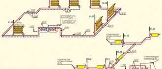
Automatic water supply system layout diagrams
When organizing an autonomous water supply, it is not enough to purchase the required pump model; in addition, you need to take care of organizing the automation.
An example of an automatic water supply system layout diagram
There are several device layout options:
- "Pump in a barrel." The circuit is so named due to the location of the nodes in a certain area. This arrangement is as compact as possible. It was possible to achieve mobility due to a flexible hose that recharges the hydraulic accumulator. The automation is installed on a water well device, and the control units are brought to the surface.
- The device module is located on the hydraulic accumulator. The device for water supply to the house and the area adjacent to it is represented by the arrangement of nodes on the surface of the battery. The collector is connected to the output pump hose, which is located directly in the well.
- Modern stations are installed near the cold water collector, which allows the required pressure to be achieved. The hydraulic accumulator is located under the bathtub, and the water line will depart from the pump.
The unit responsible for the operation of the equipment is called press control. This flow switch is designed to start the pump when the tap is opened. If it closes, the press control reacts by turning off the equipment. This device is usually used for surface devices.
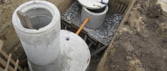
Installation of a submersible pump and its connection
To install a submersible pump, they usually use a head placed in a caisson pit along with the equipment or an adapter cut into the side wall of the casing. In the latter case, all automatic units are located in a residential building or a separate outbuilding.
Fig. 13 Diagram of connection and installation of deep-well pumps in a well
Automation for a well should be selected according to the main criteria, which include the cost associated with the submersible electric pump used. When using inexpensive electric pumps of domestic or Chinese production, it is enough to use the simplest automatic devices - the functions of expensive control units with such units will not be fully realized. If you purchase an expensive device (for example, a Grundfos electric pump for $1000) with frequency control of the electric motor rotation speed, using any other devices other than the native Grundfos PM2 module does not make any sense.
Recommendations from experts
When organizing automation for a private home, you should understand that it is not always easy to assemble the device yourself. This will be especially difficult for owners who have not previously encountered the peculiarities of such installation. Before starting any work, it is recommended to read the advice of experienced craftsmen.
Advice from experts when configuring automatic water supply:
- If you plan to use a deep-depth device, it is better to purchase a ready-made, assembled automation kit and abandon the self-assembled device, because even the slightest design error will result in the failure of all equipment.
- For a vibration device, the automation must be of high quality, and for a circulation device, a housing in which the electrical contacts are located is suitable.
- As for submersible pumps, this equipment is recommended for use only in wells with clean water. If there are impurities in the water, the device reacts by shutting down or completely failing.
Note! Metal-plastic pipes for cold and hot water supply
When organizing automation for a pump, you should take into account the type of equipment used. Only with this in mind can you select a suitable automatic system. It is not recommended to save on this. High-quality layout models will ensure smooth operation of the pumping station and prevent its rapid failure.
How to make a water pump with your own hands at home
Summer residents are not lazy and savvy people. Therefore, the question of how to make a water pump with your own hands without electricity is asked quite often. In fact, there are many options, all of them are quite feasible. One of the most effective and most affordable is a pump based on a pump mechanism. This is the type that is most often used in conditions where there is no electricity.
To create a pump you will need the following elements and parts:
- PVC pipe with a diameter of 5 cm;
- PPR pipe with a diameter of 2.4 cm;
- two 0.5 inch check valves;
- pipe plugs and bends;
- 8 mm bolts with nuts, rubber gaskets.
The pump is assembled from the above parts. The main thing is to ensure the tightness of the structure, otherwise the mechanism will not work. The piston creates pressure in the working chamber. Under its influence, water, passing through the valves, is supplied to the outlet. It is very important that the gaskets fit tightly.
It is difficult to perceive when described, but in fact it does not cause problems to create a pump powered by solar energy with your own hands. The operating principle is somewhat reminiscent of how a submersible pump is connected to a hydraulic accumulator: gas takes part in pushing out water.
A pump based on a pump mechanism is the most affordable to make yourself.
Required components:
- metal grate;
- rubber bulb;
- cylinder with propane-butane mixture.
The grate is filled with gas and connected to the bulb. The pear is placed in a tank pre-equipped with valves for inlet and outlet. Solar energy expands the gas, the latter pushes out air, providing a pressure difference in the water tank.
Note! All tank seams must be sealed tightly. Such a pump must be located in a well-lit place.
Automatic pump control - overview of pressure switches
Autonomous (decentralized) water supply systems are arranged according to certain schemes that require accurate calculation of all parameters. But just laying pipes and installing a device for pumping liquid at the source is not enough to ensure the efficiency and reliability of engineering communications. It is impossible to do without automation that controls the operation of the pump. In its simplest design, it is represented by a pressure switch, which periodically (if necessary) turns it on/off.
Note : It should be taken into account that the pressure switch can only work in conjunction with a hydraulic accumulator (more about these products here).
In pipe systems where the installation of such a tank is impossible (undesirable), or with a complex communication scheme where high-quality control of several parameters is necessary, more advanced automatic control of pumping equipment (block type) with the inclusion of various sensors is used. Information on devices of this group is available at this link.
Pressure switch - brief overview of models
The operating principle of all products in this category is identical. The algorithm is the simplest: the pressure in the system has dropped below critical - the relay turns on the pump; has increased to the maximum set value (during setup) - the contacts break its power supply circuit.
Unipump
A good domestic development, characterized by high quality and reasonable cost. It is supplied to the market in various modifications.
- Designed to work with pumps with power up to 1.5 kW.
- A pressure gauge built into the pressure switch housing. Therefore, there is no need to install the measuring device separately.
- Connections are a quarter inch.
More detailed information on Unipump brand products, setting limits and costs can be found here.
Grundfos
Reliable pressure switches from the Danish manufacturer with an impeccable reputation “GRUNDFOS”.
- High degree of protection (IP52). Such products are suitable for installation even in places with excessive humidity (damp basements, caissons, etc.).
- Reliability in operation.
- Some modifications (for example, FF 4-4 or 4-8) are low-current devices. They cannot be connected directly to the industrial/voltage network, only through an “intermediate link” in the form of a special device (converter).
- Impressive assortment. The relays differ mainly in the value of the upper limit of operation.
Many experts are unanimous in their opinion - most of the cost of the Grundfos pressure switch comes from brand “recognition”. An analysis of the operation of such automation shows that domestic analogues are in no way inferior to the “Danes”, although their price is much lower.
Condor
This is an example of German industry, which has won a lot of sympathy due to its trouble-free operation.
- The pressure switch is two-pole. That is, when triggered, both circuits (phase and zero) are simultaneously opened, which makes the operation of the system safer.
- Adjustment is made by rotation.
- Versatility of settings.
- It is possible to connect a pressure gauge.
- The cost is high.
Danfoss (KP1 series)
Pressure switch from a well-known Danish manufacturer. It is expensive, but the high price is well justified.
- Gold plated contacts. Therefore, “sticking” is excluded.
- The presence of an adjustment scale allows you to do without an indicating device (pressure gauge).
ACP PM5
This Chinese product is often confused with a “dry running” relay, although its purpose in the circuit is completely different. The only plus is the low cost.
But such “cheapness” also has a downside. Here are just the main shortcomings that are noted by users on thematic forums.
- Contacts are not silver plated (regular). Consequently, due to their burning, the circuit may not open at the right time.
- Moisture and dust resistance is zero.
- They do not fulfill their guaranteed service life - they break quite quickly.
ITALTECHNICA
Relay from Italian manufacturer. The PM/5 modification is used in conjunction with pumps. Attracts with its low price and excellent quality and reliability. Mounted in the control circuits of the cold water circuit. Pressure control limits (bar) – from 1 to 5 (lower/upper). The warranty is short - only a year.
If the water supply system does not have a pump, but a station, then it is equipped with modification G. Its main difference is within the setting range - from 1.4 to 2.8.
- Contact group - copper lamellas.
- Non-stick coating – Ag-Ni layer.
- Plastic housing with insulating gasket.
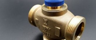
Check valve
It allows water to flow in only one direction, from the well to the water supply system. Valve elements - cover, body, spring, disc stem with rubber gasket. Well pumps with built-in automation already have this valve. If it is not built-in, then it is installed separately, immediately behind the well pump.
Under the pressure of water, the plate moves and allows water to flow into the pipe. During the reverse movement, the plate rests on the protrusions (seat) and hermetically closes the valve lumen.
The Zagorod company recommends ITAP check valves (Italy). The valve body is made of brass, the disc is made of nylon and the seal is made of hard NBR rubber. Operating temperatures – from -20 to 100 degrees Celsius. Valves from Tiemme, Danfoss, and Valtec have also proven themselves well.
What to consider
The simplest modifications of pressure switches are single-pole. This means that their contacts open only 1 line. And here is the “pitfall”. If the product is included in the circuit by a non-professional, then he can confuse the phase with zero and install it precisely in the circuit of the latter. Consequently, when the contacts open, the pump will remain energized.
In addition, when choosing a pressure switch modification, it is necessary to take into account the peculiarities of a specific water supply scheme. Advice from “experts” will not help much. First of all, such indicators as the characteristics of the hydraulic accumulator and the pumping device (including the type of pump) are meant.
Experts will help those living in the Moscow region purchase the best option for a pressure switch. You just need to call the number, and its employees will give a qualified and detailed answer to any question the client may have about pump control. They themselves will determine the characteristics of the regulating product, taking into account the parameters of the system, take into account all the nuances of its functioning and offer the most rational solution. If necessary, they will go to the site, install a pressure switch and adjust its operation limits.
Note! Water pump activation relay
Automation for a well pump: connection diagram
Automation for pumps is divided into several types of devices that have different operating principles.
Let's start looking at them one by one, starting with the simplest ones.
So, the simplest elements of automation are mechanical pressure switches.
Water pressure switch for pump: how to connect
Pressure switches are installed at pumping stations with a hydraulic accumulator and operate according to the following principle:
- The relay turns on the power to the pump when the water pressure in the system drops below the switch-on level (most often 1.5 atmospheres)
- If water is being drawn (for example, the kitchen faucet or shower is open), the pump continues to work.
- After the water withdrawal stops, the pump operates until the pressure reaches the circuit opening level (most often 3 atmospheres)
A pressure switch is the simplest and most common type of automation for pumps.
With its help, you can make a pumping station from any pump that is capable of developing the pressure necessary to turn off the relay.
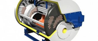
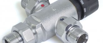
It is usually connected either to a special seat in the pump housing, or through a fitting called a five-pin fitting (see figure).
Five-pin fitting for connecting a relay
In addition to the relay, you can connect a hydraulic accumulator and a pressure gauge to it.
Pump dry running protection relay: operating principle
There is another type of pressure switch - a dry-running protection relay. It is also sometimes called a dry run sensor or DSH.
This relay works the other way around:
- During normal pump operation, water pressure keeps the DSH contacts closed.
- When the water pressure in the main drops below a threshold level, the DSH opens the electrical circuit and turns off the pump. The threshold pressure level lies in the range of 0.1 - 0.8 atmospheres.
A dry-running protection relay can operate on surface and deep-well pumps, as well as at pumping stations, and is the easiest way to protect the pump from damage in the event of a loss of water.
How does a pump float switch work?
The float switch turns the pump on and off depending on the liquid level in the container.
That is, when the liquid level in the container drops to a minimum, it turns on the pump, and when the maximum level is reached, the pump turns off.
Float switches come in different power cord lengths.
The immersion level of the float is regulated by a special weight that comes with the kit.
A float valve is a very simple and reliable solution for filling containers using a pump.
Automatic water level control
Such machines are used to maintain the required level of liquid in storage tanks.
They are distinguished from float switches by the type of sensors - here they work by closing or opening a circuit.
They will not work if the liquid in the container does not conduct electricity. Such a liquid would be, for example, distilled water.
Float valve for container or tank
Another solution for filling a container with water is a float valve.
It does not require electricity to operate - it opens under the influence of gravity, and closes when the water rises to its maximum level.
This system was previously used to fill toilet cisterns. The disadvantage of a float valve is that it takes a long time to fill the container.
Well pump control unit: connection diagram
The pump control unit is a special device that controls the operation of the pump.
The pump control unit can perform the following functions:
- Provides constant pressure in the system with different water distributions - convenient when using instantaneous water heaters and automatic irrigation systems.
- Provides protection against dry running.
- Limits the frequency of pump activation - prolongs the life of the pump motor.
- Has a built-in check valve.
In addition, the control units are easy to install and have small dimensions.
Connection diagram for Espa unit model kit 06
Everything described above is not available in all models and not all manufacturers.
There are many cheap Chinese units on the market that can maintain the pressure in the system within a certain range (working with or without a hydraulic accumulator) and protect against “dry running”. This is where their capabilities end, but the price remains reasonable.
The control unit has a limitation on the power of the connected pump.
Most often, the power is limited to 1.5 kW, but there are models that are designed for a power of 2.2 kW.
If the power limit is not specified, then there must be a current limit (usually from 10 to 20 Amps).
If it is necessary to install it on a powerful pump , it is necessary to use the pump power connection via a starter.
In addition, the blocks have restrictions on water consumption.
Exceeding the recommended flow rate may cause damage to the unit, which will not be covered under warranty.
This problem can be circumvented by installing the unit on bypass.
Installing the pump control unit on bypass
The cross-section of the pipe from which it is made must be smaller than the cross-section of the main line, then the main flow will not flow through it, but this will be enough for the control unit to operate correctly.
Features of connecting a hydraulic accumulator to a well
The article mentioned a hydraulic accumulator (also known as a hydraulic tank, a membrane tank) more than once. In general, the purpose of this element of the water supply system is clear, but its role is so important that the issue requires a more detailed consideration.
The principle of operation of the tank is as follows:
- water enters the membrane, the free gas is compressed, increasing the pressure on the stretched rubber;
- the tank is full - the relay turns off the pump;
- after opening the tap, the pressure drops, the relay turns on the pump again and brings the pressure indicator to the required value.
The operation of the membrane tank described above directly indicates that the main type of automation for a well pump with a hydraulic accumulator is a pressure control relay. The tandem of the membrane tank and relay significantly increases the service life of the pump, since it provides protection against water hammer when starting the pump, and also reduces the frequency of switching on - a small amount of water is supplied from the tank.
Garden pump: how to choose a submersible pump for a garden (read more)
When connecting a hydraulic accumulator to a well, installing a check valve is of great importance. Its main function is to prevent water from going back into the well. The valve is mounted on the pump at its connection with the supply pipe. Mounting method: threaded. The thread is cut into the pump cover. The installation of the system has a strict sequence: first the valve is installed, then the hydraulic accumulator is connected.
Installing a check valve when connecting a hydraulic accumulator to a well plays a key role.
On a note! In conditions of unstable replenishment of the water layer, it is worth purchasing an automatic pump with a hydraulic accumulator with a water search function (automatic reboot) after the dry-running protection is activated.