Time relay Buy from 2250 rub.
A time relay with an off-on delay is designed to automate the control of liquid pumps and other electrical devices. It allows you to program on/off intervals and thereby divide the operating time of devices into equal or different time cycles.
Briefly about the time relay
A time relay is a device whose main task is to periodically turn on/off the power supply to the load. Moreover, the latter can be either a street lamp or an industrial pump. Time relays are an excellent tool for automating cyclic processes that are performed in strictly specified time periods.
Based on practice, I will say that with a well-thought-out operating algorithm, entire production lines are organized using time relays. The main thing is to carefully calculate everything and set the on/off time correctly.
Do-it-yourself homemade electrical contact pressure gauge
Hello! Many people know firsthand about such a measuring device as a pressure gauge. But many people find it difficult to imagine the device and the principle of its operation.
A pressure gauge is designed to measure the pressure of a liquid or gas. Moreover, the pressure gauge for measuring gas and liquid pressure is not structurally different from each other. So if you have a pressure gauge lying around somewhere to measure liquid pressure, then you can safely use it to measure gas pressure and vice versa.
Design and principle of operation of the pressure gauge
To better understand how the pressure gauge works and works, look at the figure below.
The pressure gauge consists of a body with a measurement scale, a copper flat tube 1 folded in the shape of a circle, a fitting 2, a transmission mechanism 3 from the tube to the pointer 4. Using the fitting, the pressure gauge is wrapped in a vessel where the pressure of the medium (gas or liquid) is to be measured.
How does a pressure gauge work?
When gas and liquid under pressure are supplied through fitting 2, the folded tube 1 will tend to straighten, and through the transmission mechanism the movement of the tube will be transmitted to the arrow 4. It, in turn, will indicate the amount of pressure, which can be read using a scale. When the pressure decreases, the tube will collapse again and the arrow will indicate a decrease in pressure.
Electric contact pressure gauge device
I think you can guess how an electric contact pressure gauge works. Its design is no different from a conventional pressure gauge, except that it has built-in contacts. There are usually two of them and their position on the pressure gauge scale can be changed.
What if you don’t have an electrical contact pressure gauge, but you really need one? What to do then? Then you need to make a homemade electric contact pressure gauge.
I'll tell you how to make a homemade electric contact pressure gauge. To do this, you will need a simple pressure gauge, two small strips of tin from a tin can, double-sided tape and two thin wires.
Using a sharp awl, pry up and remove the large retaining ring. Then remove the glass and then the rubber washer. Drill two holes in the pressure gauge housing to allow two wires to pass through them.
Cut two strips from tin and bend them in the shape of the letter L. Solder a thin insulated wire to the base. From double-sided tape, cut two strips equal in size to the strips and stick it on the strips. Next, glue the resulting contacts to the pressure gauge scale within the specified pressure limits.
Pass the wires through the holes and bring them out.
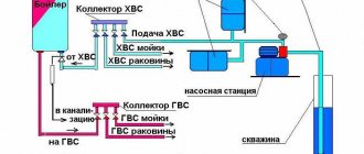
Reinstall the rubber gasket and then the glass. Secure everything with a locking ring. That's it, the homemade electric contact pressure gauge is ready. For example, I used this in a homemade automatic water supply system for a private house.
Connection diagram for electrical contact pressure gauge
In order for this pressure gauge to influence any actuator, a special circuit is needed. You can see an example of this scheme in the figure below.
At a minimum pressure of the medium (gas or liquid) in the electric contact pressure gauge, contacts 1 and 2 will be closed. In this case, the electromagnetic relay K1 will operate. It, in turn, with its contacts K1.1 will supply power to the winding of the magnetic starter K3. Using contacts K3.1, it will bypass contacts K1.1, and when the contacts in pressure gauge 1 and 2 open, relay K1 will release its contacts K1.1. But at the same time, the starter winding K3 will continue to flow around with current. With its contacts K3.2, the magnetic starter will supply power to the motor M of the pump or compressor.
With a further increase in pressure in the pressure gauge, contacts 1 and 3 close. At the same time, the electromagnetic relay K2 will operate and with its contacts will open the power circuit of the coil K3 of the magnetic starter. Contacts K3.2 will open and the power supply to motor M will disappear. With a further decrease in pressure and the closure of pressure gauge contacts 1 and 2, the cycle will repeat.
Setting the delay on the time relay
The procedure for setting the turn-on and turn-off delay depends on the specific device model and its functionality. For example, the TDR60s has only one switch, which is responsible for setting the time after which the device will stop supplying voltage to the load.
Time relay TDR60s
In my opinion, a more interesting procedure for setting the delay is for the TDR26 time relay.
Time relay TD26
In this model, the user will have to sequentially program three delay parameters. One is responsible for the time range and two multipliers (x1 and x10). For example, to set a delay of 3 seconds, you need to make the following settings: set the range to 1s, and the x1 multiplier to 3. To set the parameter to 30 minutes, you will need to select the 1m range and set the x10 multiplier to 3.
Setting up the TRD26s time relay
RF with switch-off delay 220V with 3 best devices from aliexpress
Buying a relay on the aliexpress portal saves money. We present three of the best devices on this service.
| Number in the rating | Name | pros | Flaws |
| First | Digital LED Display Time Delay Relay Module Board DC 12V Control Programmable Timer Switch Trigger Cycle Module With Case | Digital indicator, presence of housing | To control 220V devices you need an intermediate relay |
| Second | AC 220V H3Y-2 Power On Time Delay Relay Solid State Timer 1.0~30 Min Socket Base | Ability to work on a 220 V network, convenient setup | Limit delay time 30 min |
| Third | Programmable Delay Relay DH48S-S with socket base | Unlimited exposure time, presence of housing, possibility of remote adjustment | Price |
Number one, two and three in our relay rankings
Work algorithm
An important feature of time relays is that supplying voltage or cutting off the load after a specified period of time is only one of the functions of these devices. Advanced models support various operating algorithms. The simplest time relays simply disconnect the equipment from the network after the delay time has expired. More advanced devices are capable of starting the delay count only after a time has passed after voltage is applied or implement cyclic on/off. In some cases, it is possible to start the delay count only when a signal is given from the button.
What are time relay operating diagrams and how do they differ?
Actuation diagrams are a visual visualization of how a time relay will behave in a specific period of time when executing a particular algorithm. With their help, the user can quickly determine the optimal mode for solving a specific problem. This is especially important if you need to perform a whole cycle of actions.
Please pay attention! To switch the operating algorithm, some time relays use terminals rather than a switch. Therefore, when connecting them in series, it is important to strictly follow the instructions in the instructions for the device in order to avoid incorrect operation and false alarms.
Weekly digital timer
A digital weekly timer or electronic time relay is a flexible, programmable device designed to operate within seven calendar days. With its help, it is possible to set the exact dates of necessary switching (connections or disconnections of specific loads) in public institutions such as schools, offices and similar places of collective use.
“Advanced” samples of daily time relays provide the ability to save copies of several programs with the ability to read them. Various types of drives are used as storage media, allowing it to be removed using an electronic key D KEY (in the PLUS and SYNCHRO system versions).
Which work diagram to choose
The choice of a specific diagram of the operating mode of a time relay depends on what tasks the device must solve. Using the TDR26 model as an example, I will show what operating modes are available in it.
Delay due to sudden power cut. The relay turns off the load only after a specified time after the power supply from the network has stopped.
Operation diagram of time relay TRD26s A
Turn-on delay when power is present. The device turns on when there is no power. Automatic shutdown occurs only when the set time has elapsed. In the event of power supply, the relay interrupts the countdown and turns off.
Diagram of operation of time relay TRD26s B
Delay in power on and off. After connecting the relay to the network, a report is launched, upon completion of which the device turns on. Then a new countdown begins to turn off the time relay.
Diagram of operation of time relay TRD26s C
Turn-on delay. The device turns on upon completion of the calculation of time after power supply and turns off only if it is interrupted
Diagram of operation of the TRD26s CD time relay
Shutdown delay. The device turns on when connected to the network and turns off automatically after a specified time.
Diagram of operation of time relay TRD26s E
Should be considered! To solve complex problems of automatically turning on/off an electrical circuit, you can install several time relays. In this case, it is possible to configure their operating algorithms in such a way that each device performs a specific action when a particular situation arises in automatic mode.
Connection diagram for a starter with a 220 V coil
In any magnetic starter connection diagram there are two circuits. One power line through which power is supplied. The second is a signal one. This circuit controls the operation of the device. They need to be considered separately - it’s easier to understand the logic.
At the top of the magnetic starter housing there are contacts to which the power for this device is connected. The usual designation is A1 and A2. If the coil is 220 V, 220 V is supplied here. It makes no difference where to connect “zero” and “phase”. But more often the “phase” is supplied to A2, since here this output is usually duplicated in the lower part of the case and quite often it is more convenient to connect here.
Connecting power to the magnetic starter
Below on the case there are several contacts labeled L1, L2, L3. The power supply for the load is connected here
Its type is not important (constant or alternating), it is important that the rating is not higher than 220 V. Thus, through a starter with a 220 V coil, you can supply voltage from a battery, wind generator, etc.
It is removed from contacts T1, T2, T3.
Purpose of magnetic starter sockets
The simplest scheme
If you connect a power cord (control circuit) to pins A1 - A2, apply 12 V voltage from the battery to L1 and L3, and lighting devices (power circuit) to pins T1 and T3, we get a lighting circuit operating on 12 V. This is only one of the options for using a magnetic starter.
But more often, these devices are used to supply power to electric motors. In this case, 220 V is also connected to L1 and L3 (and the same 220 V is removed from T1 and T3).
The simplest diagram for connecting a magnetic starter - without buttons
The disadvantage of this scheme is obvious: to turn the power off and on, you will have to manipulate the plug - remove/insert it into the socket. The situation can be improved if you install an automatic machine in front of the starter and turn on/off the power supply to the control circuit with its help. The second option is to add buttons to the control circuit - Start and Stop.
Diagram with “Start” and “Stop” buttons
When connected via buttons, only the control circuit changes. The strength remains unchanged. The entire connection diagram of the magnetic starter changes slightly.
The buttons can be in a separate case, or in one. In the second version, the device is called a “push-button post”. Each button has two inputs and two outputs. The “start” button has normally open contacts (power is supplied when it is pressed), the “stop” button has normally closed contacts (the circuit breaks when pressed).
Connection diagram of a magnetic starter with “start” and “stop” buttons
Buttons are built in front of the magnetic starter in series. First - “start”, then - “stop”. Obviously, with such a connection scheme for a magnetic starter, the load will only work while the “start” button is held down. As soon as she is released, the food will disappear. Actually, in this version the “stop” button is superfluous. This is not the mode that is required in most cases. It is necessary that after releasing the start button, power continues to flow until the circuit is broken by pressing the stop button.
Connection diagram of a magnetic starter with a self-recharging circuit - after closing the contact shunting the “Start” button, the coil becomes self-feeding
This operating algorithm is implemented using auxiliary contacts of the starter NO13 and NO14. They are connected in parallel with the start button. In this case, everything works as it should: after releasing the “start” button, power flows through the auxiliary contacts. Stop the load operation by pressing “stop”, the circuit returns to the operating state.
Types of time relays
In addition to the configuration features and operating algorithms, time relays differ in the design of the housing. The most common among consumers are block and modular. The first ones are designed for household consumers and are made in the form of an adapter for an outlet. On the front panel of these devices there are control buttons and a display for setting the operating algorithm.
Modular models of time relays can be used by both household and industrial consumers. Their housing is designed in such a way that the devices can fit into the switchboard. Mounting options are provided for installation on a standard DIN rail.
Liquid crystal display
LCD Display Data
At the top of the display: days of the week MO - Monday; TU - Tuesday; WE—environment; TH - Thursday; FR - Friday; SA - Saturday; SU - Sunday. The day of the week is set with the D+ button. In the middle part of the display: current and programmable time. The time is set with the , H+ and M+ buttons. In the lower left part of the display: numbers of on and off cycles ON - on; OFF - disabled; numbers from 1 to 16 - cycle number. Cycles are configured using the button in the lower right part of the display: control mode ON - constantly on; AUTO - automatic mode; OFF - permanently disabled. The control mode is set using the MANUAL button