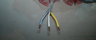
In industry, grounding has been used for a long time; in housing, it began to be used relatively recently. True, a lot has been written about grounding in the electrical installation rules (PUE). It clearly describes how the grounding loop should be carried out, what elements should be used in it, the parameters of the grounding loops and everything else. That is why this current leakage protection system must be treated with full responsibility, meaning installation, calculation and maintenance. So, grounding (the PUE is the basis) determines the safety of operation of electrical networks.
Grounding system terms
Before moving on to considering the rules for installing grounding, it is necessary to define the terms used by specialists when carrying out this type of work.
- Firstly, what is a grounding device? This is a structure consisting of a grounding conductor and grounding conductors.
- Secondly, what is a ground electrode? This is a metal conductor that is directly connected to the ground.
- Third, what are grounding conductors? This is a system of metal conductors that connect the ground electrode to electrical equipment.
Please note that grounding an electrical installation artificially is called intentional. There is such a thing as the resistance of a grounding device. This is, in fact, the sum of the resistances of the grounding conductor and grounding conductors. If we talk about the resistance of the ground electrode itself, then this is the voltage relative to the ground to the current passing through the metal conductor.
Electrical Safety Protective Measures
If you strictly follow all the rules during operation, the use of electrical appliances does not pose any danger. Protection against electric shock is achieved in the following ways:
- the part of the electrical circuit through which the current passes must not be accessible to accidental touch;
- live parts that are open must not contain voltage dangerous to human life, even if the insulation is broken;
- such inaccessibility is achieved through protective shutdown, the use of low voltage, double insulation, equalization and potential equalization, the implementation of barriers, and the location of electrical equipment outside the accessibility zone.
The use of measures in combination to protect against electric shock should not reduce the effectiveness of each. If the electrical equipment is located in the potential equalization area, and the highest operating voltage is no higher than 25V AC and no more than 60V DC, then there is no need for protection against direct contact.
Also, the protective functions of electrical equipment must be provided during the manufacture of the latter, or during installation.
Artificial and natural grounding electrodes
We have understood the terms, now we can consider which conductors can be used as a grounding conductor. From the title of the section it becomes clear that they can be either natural or artificial.
Natural ones include metal systems of underground pipelines (water supply, sewerage, wells) or metal structures of buildings and structures that go deep into the ground.
Attention! Pipelines laid underground can be used as natural grounding only if the pipe joints were connected by gas or electric welding. It is prohibited to use oil, gas and petrol pipelines for these purposes. This is clearly stated in the PUE.
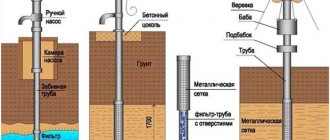
As for artificial grounding conductors, metal profiles are most often used for this, which are driven into the ground to a depth of 2.5 to 3 m. Most often, steel corners with a shelf width of 50 mm, fittings or pipes are used for these purposes. A prerequisite is to leave 10 cm of protruding profile above the ground surface. There should be either four or three grounding electrodes; they are installed either in a square or in a triangle. The protruding ends are tied with round reinforcement with a diameter of 10-16 mm or a steel strip 30 mm wide. All joints are made only by electric welding.
Pipe stands
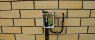
To install an entry device in a commercial building or country house, you must use a pipe stand.
Its main task is to fix the power wire that leads to the shield, as well as install the shield itself. According to the requirements of the PUE rules, the pipe stand requires mandatory grounding.
Not far from the shield, you need to drill a hole through which it is important to place a grounding bolt. Both the pipe stand itself and the shield require high-quality grounding. A metal corner one and a half meters long should be driven in not far from the rack. Next comes the connection of the pipe stand, shield and corner.
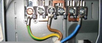
The zero bus is also protected. The neutral wire marked SIP4, which comes from the support, must be connected to it. To perform the operation, you need to use the yellow-green wire marked PV-3, on which the tips are installed. At this point, the grounding of the metal pipe stand can be considered complete.
Installation rules
Attention! All connections of the grounding system are made only by welding, where two elements or sections are overlapped. The quality of such a connection will be checked by hitting a kilogram hammer. Welded joints must be treated with bitumen-based varnish.
Now, regarding the wiring of grounding conductors. They can be carried out on concrete and brick structures, both in the horizontal and vertical planes. Fastening to structures is done with dowels, between which you can leave a distance:
- on straight sections in the range of 600-1000 mm;
- on bends and turns no more than 100 mm.
The distance from the floor base to the fastening point should be 400-600 mm. If the grounding system of conductors will be laid in wet rooms, then under them it will be necessary to lay pads with a thickness of at least 10 mm.
Rating of the best industrial kits
Factory-produced kits are easy to assemble. The owner of a house or warehouse can install the circuit himself. Installation requires a minimum of preparatory work. The components are placed in cardboard containers, which simplifies the transportation process and protects the parts from damage. The components are made of steel rod coated with copper, which ensures increased service life.
The ends of the pins are threaded, and the kits come with special tips that make it easier to drive the rods into dense soil.
Zandz ZZ–000–045
The Russian-made module consists of prefabricated electrodes with a length of 5 to 15 m (depending on the number of elements). The kit is used for grounding residential or office buildings and provides protection against lightning. Supplied as a kit containing threaded couplings for assembling electrodes from blanks. The surface of the steel pins is covered with a layer of copper; attachments for a jackhammer are provided (necessary during installation work). The average price of a set is 70 thousand rubles.
Galmar GL–00045
The set includes 30 metal pins 1.5 m long and connecting threaded elements. The surface of the electrodes is coated with copper, which provides resistance to corrosion. There are clamps for connecting conductors, starting tips for electrodes and attachments for a jackhammer, allowing you to quickly bury the pins in the ground.
The components are supplied as a set, packed in a box made of thick waterproof cardboard. The average cost of a set is 70 thousand rubles.
Ezetek CN-6
The budget set includes an electrode made of stainless steel and having a length of 6 m. A carbide tip is provided, which simplifies the procedure for installing the pin in the ground. The electrode is assembled from 1.5-meter elements; threaded bushings are used for connection. There is a tube with a special paste that conducts electric current. The kit is designed for use in private homes or country houses; installation is carried out using a hammer drill or sledgehammer. The price of a grounding system starts from 12 thousand rubles.
Rules for grounding pipelines
Grounding of pipelines is a mandatory measure, enshrined in the PUE. This is how you can increase the safety of their operation, because static electricity accumulates in pipe systems, plus there is always the possibility of lightning striking the pipes. The requirements of the rules for the construction of electrical installations are to provide grounding not only for external pipelines, but also for internal ones (technological and communication).
The PUE clearly regulates how pipelines should be grounded.
- Firstly, the pipe system must be a single continuous network connected into a single circuit.
- Secondly, pipelines must be connected to the grounding system at at least two points.
As for the first position, this does not mean that the pipeline system itself must be continuous. Here it will be enough to ensure the connection of sections or individual pipelines into one single network, for which so-called wafer jumpers are most often used. In fact, this is an ordinary copper wire of the brand either PVZ or PuGV. Fastening of jumpers to the pipeline is ensured by welding, bolting, or a grounding clamp for pipes is installed.
As for the second position, experts recommend not to scatter along the entire line of the technological chain, just to make a connection at the beginning and end of the circuit.
Explosive areas
Taking into account the design and purpose, we can distinguish:
- oil pipelines and gas pipelines;
- systems through which alcohol-containing liquids/gases are transported.
Transportation of explosive and fire hazardous substances imposes increased safety requirements. The standards are described in the PUE (chapter 7.3).
In the case of explosive premises, the use of natural grounding conductors is permissible only if they provide additional protection. The main one should be an artificially constructed circuit.
1.7.61
When using the system, it is recommended to re-ground the PE
- and
PEN
conductors at the entrance to electrical installations of buildings, as well as in other accessible places. For re-grounding, natural grounding should be used first. The resistance of the re-grounding electrode is not standardized.
Inside large and multi-storey buildings, a similar function is performed by potential equalization by connecting the neutral protective conductor to the main ground bus.
Re-grounding of electrical installations with voltages up to 1 kV, receiving power via overhead lines, must be carried out in accordance with 1.7.102-1.7.103.
Secondary protection of reinforced concrete involves applying a special coating
For slightly aggressive soils, primary protection methods are mainly used, and secondary methods are used as necessary. In moderately aggressive soils, it is necessary to use both primary and secondary protection, the latter limiting the access of substances that cause corrosion to reinforced concrete. Finally, in soils with a high degree of aggressiveness, both primary and secondary protection methods are mandatory, and the secondary methods must completely isolate the reinforced concrete from the action of the aggressive environment.
Self-production
Making your own grounding is a sequential process consisting of several stages, each of which has its own characteristics. This does not require a pile of papers, since permission is not required in private construction. Installation should be carried out in the warm season, when the soil has thawed, dried out and settled.
To work you will need:
- welding machine;
- grinder, hammer drill;
- level, tape measure;
- pliers;
- shovel, sledgehammer;
- brush, paint;
- corrugated tube;
- aluminum tape.
The work is performed in the following sequence:
- Drawing up a project. Based on it, calculations of materials and equipment are carried out. You should make a small reserve, as errors are possible during the work process.
- Carrying out markings. The turf layer is carefully removed, then a pit of a given shape is torn off. The excavated material must be preserved, as it will be used for backfilling.
- From the middle of one side or from the corner, a flat trench is dug towards the building. It is needed for laying a cable or other current conductor between the frame and the electrical panel.
- The electrodes are cut out. Their ends are pointed for easier immersion into the soil. After this, the pins are driven into the ground at the corners of the trench. If a corner is used, holes are pre-drilled and the openings are filled with a mixture of earth and salt.
- The sides of the contour are cut out. They are connected to the electrodes and to each other. Welding areas are painted over.
- Near the ditch to the house, a bolt is welded to the frame. The cable is screwed to it. The joint is closed with a plastic bottle, the neck of which is sealed with aluminum tape.
- Entry into the house is made in the basement. To prevent chafing of the cable insulation, a flexible steel tube is inserted into the hole. The cable is pulled into it and connected to the shield.
- The final stage is filling the ditches with soil, leveling it and compacting it.
Effect of insulation
The insulation resistivity indicator can significantly influence the characteristic features of the pipeline. According to studies, the level of resistance in the grounding of a pipeline using bitumen insulation can greatly depend on the potential difference between the soil and the pipeline itself.
If the difference varies within a few hundred volts, glow discharge may occur at defective locations, which in turn reduces the ground resistance. If the potential difference is one kilovolt or more, an arc discharge appears between the soil and the pipeline.
It, accordingly, greatly reduces the resistance of the installed grounding. Portable grounding can also be used, in which the clamp is the main part.
1.7.102
At the ends of overhead lines or branches from them with a length of more than 200 m, as well as at the inputs of overhead lines to electrical installations in which automatic power off is used as a protective measure in case of indirect contact, repeated PEN
- conductor. In this case, first of all, natural grounding devices should be used, for example, underground parts of supports, as well as grounding devices intended for lightning overvoltages (see Chapter 2.4).
The specified repeated groundings are performed if more frequent groundings are not required under the conditions of protection against lightning surges.
Re-grounding PEN
-conductors in DC networks must be made using separate artificial grounding conductors, which should not have metal connections to underground pipelines.
Grounding conductors for re-grounding PEN
- the conductor must have dimensions no less than those given in Table 1.7.4.
1.7.55
For grounding in electrical installations of different purposes and voltages that are geographically close, one should, as a rule, use one common grounding device.
A grounding device used for grounding electrical installations of the same or different purposes and voltages must meet all the requirements for the grounding of these electrical installations: protecting people from electric shock when the insulation is damaged, operating conditions of networks, protecting electrical equipment from overvoltage, etc. during the entire period of operation.
First of all, the requirements for protective grounding must be met.
Grounding devices for protective grounding of electrical installations of buildings and structures and lightning protection of categories 2 and 3 of these buildings and structures, as a rule, should be common.
When installing a separate (independent) grounding system for working grounding under the operating conditions of information or other equipment sensitive to interference, special measures must be taken to protect against electric shock, preventing simultaneous contact with parts that may be exposed to a dangerous potential difference if the insulation is damaged.
To combine grounding devices of different electrical installations into one common grounding device, natural and artificial grounding conductors can be used. Their number must be at least two.
1.7.100
In electrical installations with a solidly grounded neutral, the neutral of a three-phase alternating current generator or transformer, the midpoint of a direct current source, one of the terminals of a single-phase current source must be connected to the grounding conductor using a grounding conductor.
An artificial ground electrode designed to ground the neutral, as a rule, should be located near the generator or transformer. For intra-shop substations, it is allowed to place the ground electrode near the wall of the building.
If the foundation of the building in which the substation is located is used as natural grounding, the neutral of the transformer should be grounded by connecting to at least two metal columns or to embedded parts welded to the reinforcement of at least two reinforced concrete foundations.
When built-in substations are located on different floors of a multi-story building, the grounding of the neutral of the transformers of such substations must be carried out using a specially laid grounding conductor. In this case, the grounding conductor must be additionally connected to the building column closest to the transformer, and its resistance is taken into account when determining the spreading resistance of the grounding device to which the transformer neutral is connected.
In all cases, measures must be taken to ensure continuity of the grounding circuit and protect the grounding conductor from mechanical damage.
If in PEN
- the conductor connecting the neutral of the transformer or generator with the
PEN
bus of the switchgear with voltage up to 1 kV has a current transformer installed, then the grounding conductor should not be connected to the neutral of the transformer or generator directly, but to the
PEN
conductor, if possible immediately after the current transformer.
In this case, the division of the PEN
conductor into
PE
and conductors in the system must also be carried out behind the current transformer. The current transformer should be placed as close as possible to the neutral terminal of the generator or transformer.
Aggressive soils and protection of reinforced concrete from their effects
Currently, issues of protecting reinforced concrete structures from the aggressive influence of soils are regulated in Russia by the interstate standard GOST 31384-2008 “Protection of concrete and reinforced concrete structures from corrosion. General requirements". According to this GOST, the aggressiveness of the soil is determined by the depth to which concrete collapses or loses its protective properties relative to steel reinforcement over 50 years. Weak degree of aggressiveness - less than 10 cm, medium - from 10 cm to 20 cm, high - more than 20 cm.
Primary methods of protection include changes in the composition of concrete, as well as a set of design and engineering solutions that reduce the level of corrosion. The concrete must be denser, providing better protection for the steel reinforcement than usual. Secondary measures include applying protective coatings to reinforced concrete structures, as well as treating them with an antiseptic if the cause of corrosion is the action of bacteria.
Deaf neutral immersion
Grounding systems are divided into two large groups: with a solidly grounded neutral and with an isolated one. In the first type of circuit, the neutral conductor (denoted N) is always grounded and can be independent of the protective PE conductor, or can be connected to it to form a PEN conductor.
If the neutral wire is combined with a protective conductor, it forms a TN-C system, if carried out separately - a TN-S system, in the case when it is combined at a substation with a protective conductor, and at the entrance to the building it is divided into two conductors - protective PE and functional N , the TN-CS system is formed. Another type is a system in which the neutral conductor is grounded at the substation and three-phase current is supplied to the consumer through four wires, one of which is zero N. This is a TT system.
Application of the TN-C system
The TN-C system was widely used previously with the so-called two-wire network. In this case, there was no grounded contact in the sockets. In networks designed according to this system, the neutral wire was grounded, but if it broke, all devices remained energized. This forced the housing of each individual electrical appliance to be grounded. This system is not designed in modern buildings under construction. Only used in old buildings.
Application of the TN-S system
The TN-S system is more advanced, has a high degree of electrical safety, since it has a separate grounded conductor, but its cost is unreasonably high. With three-phase power, you have to lay five wires from the source - three phases, a neutral and a protective conductor PE.
To eliminate the shortcoming of the TN-S system, TN-CS was created. It provides one conductor PEN, which is a common wire grounded along the entire length from the power source to the entry into the building, and before entry it is divided into a neutral N and a protective conductor PE. This system also has a significant drawback. If the PEN conductor is damaged along the section from the substation to the building, all devices connected inside the building remain under dangerous voltage. For this system, the PUE (Electrical Installation Rules) require measures to provide additional protection for the PEN conductor from mechanical damage.
CT grounding type
The TT system is used to supply electricity outside the city and in rural areas through power lines installed on poles. Connecting electrical installations via this system is permitted only if it is impossible to ensure all electrical safety conditions in the TN system and avoid unjustified material costs. When contacting electrical appliances, protection against current must be carried out by turning off the power in the circuit. For this purpose, the rules prescribe special products - residual current devices - RCDs.
Influence of concrete type and soil properties on grounding parameters
The electrical resistivity of waterproof concrete, used for primary protection against aggressive soils, is significantly higher than that of conventional concrete. This is due to a denser structure containing a minimum number of pores. For waterproof concrete, the volumetric electrical resistivity can be calculated based on data on the water absorption coefficient and waterproof grade. There are also types of concrete that are resistant to aggressive environments due to the introduction of special additives into their composition. The volumetric resistivity of such types of concrete is determined by taking measurements on specific samples.
Choosing a place to place the circuit
To determine a place suitable for driving grounding electrodes, you need to go through a procedure called coordination of utility routes. Since the length of the electrodes is usually greater than the depth of power lines, communications and pipelines, the risk of damage to them is absolutely real when working within the city. Therefore, first familiarize yourself with the plans for laying communication routes; you can leave a request with the local city administration.
There may be a small monetary cost associated with this, but it is almost never necessary to obtain an excavation warrant. One interesting point is connected with the approval: you relieve yourself of responsibility for damage to the line if it is not in the register of underground communications. Moreover, even if underground routes have already been laid in an ideally suitable location, you can easily bypass them using the specified values of protection zones and anchor points. It is recommended for businesses to keep certified copies of plans on file.
Selecting the cable cross-section
The cable usually consists of 2-4 cores. The cross-section (more precisely, the cross-sectional area) of the core is determined by its diameter.
Based on practical considerations, at low current values, the cross-section of the copper conductor is taken to be at least 1 mm2, and for the aluminum conductor - 2 mm2. At sufficiently high currents, the wire cross-section is selected according to the connected power. It is usually assumed that a load of 1 kW requires a core cross-section of 1.57 mm2. From this follow the approximate values of the wire cross-sections, which should be followed when choosing its diameter. For aluminum - this is 5A per 1 mm2, for copper - 8A per 1 mm2. Simply put, if you have a 5 kW instantaneous water heater, then you need to connect it with a wire rated at least 25A, and for copper the cross-section should be at least 3.2 mm2.
Pixabay
Power cable AVVG: aluminum cores (1-4), cross-section from 2.5 to 50 mm2, polyvinyl chloride insulation, polyvinyl chloride sheath. Designed for installation in both dry and wet areas.
VVG power cable: copper cores (1-4), cross-section from 1 to 50 mm2, polyvinyl chloride insulation, polyvinyl chloride sheath. Used for laying in dry and damp areas.
Please note that from a number of preferred cross-sectional values (0.75; 1; 1.5; 2.5; 4; 6 mm2, etc.) for aluminum wires, the cross-section is chosen one step higher than for copper, since their conductivity is approximately 62% of the conductivity of copper. For example, if, according to calculations, a cross-sectional value of 2.5 mm2 is needed for copper, then for aluminum you should take 4 mm2, if for copper you need 4 mm2, then for aluminum - 6 mm2, etc.
Pixabay
Wires for internal power and lighting networks are often placed in protective corrugated plastic hoses.
VBBShv cable: copper polyvinyl chloride along the core, polyvinyl chloride sheath, armor made of galvanized steel strips, sealed outer hose. Can be used wherever there is a danger of mechanical damage to the wiring during operation.
In general, it is better to choose a cable for your home with a larger cross-section than required, in case you want to connect something else? In addition, it is necessary to check whether the cross-section of the wires is consistent with the maximum actual load, as well as with the current of the protective fuses or circuit breaker, which are usually located next to the meter.
So, you have finally decided on the material and cross-section. The next step is to select the brand of cable or wire.
1.7.68
Fences and shells in electrical installations with voltages up to 1 kV must have a degree of protection of at least IP 2X, except in cases where large clearances are necessary for the normal operation of electrical equipment.
Guards and shells must be securely fastened and have sufficient mechanical strength.
Entering the fence or opening the shell should be possible only with the help of a special key or tool, or after removing the voltage from live parts. If these conditions cannot be met, intermediate barriers with a degree of protection of at least IP 2X must be installed, the removal of which must also be possible only with the help of a special key or tool.
1.7.83
The additional potential equalization system must connect with each other all simultaneously accessible open conductive parts of stationary electrical equipment and third-party conductive parts, including accessible metal parts of building structures, as well as neutral protective conductors in the system and protective grounding conductors in systems and, including protective conductors of plug sockets
For potential equalization, specially provided conductors or exposed and third-party conductive parts may be used if they satisfy the requirements of 1.7.122 for protective conductors with regard to conductivity and continuity of the electrical circuit.
1.7.76
The requirements for protection from indirect contact apply to:
1) housings of electrical machines, transformers, devices, lamps, etc.;
2) drives of electrical devices;
3) frames of distribution boards, control panels, panels and cabinets, as well as removable or opening parts, if the latter are equipped with electrical equipment with a voltage higher than 50 V AC or 120 V DC (in cases provided for by the relevant chapters of the PUE - higher than 25 V AC or 60 V VDC);
4) metal structures of switchgears, cable structures, cable couplings, shells and armor of control and power cables, sheaths of wires, sleeves and pipes of electrical wiring, shells and supporting structures of busbars (conductors), trays, boxes, strings, cables and strips on which reinforced cables and wires (except for strings, cables and strips along which cables with a neutralized or grounded metal sheath or armor are laid), as well as other metal structures on which electrical equipment is installed;
5) metal shells and armor of control and power cables and wires for voltages not exceeding those specified in 1.7.53, laid on common metal structures, including in common pipes, boxes, trays, etc., with cables and wires on higher voltages;
6) metal cases of mobile and portable electrical receivers;
7) electrical equipment installed on moving parts of machines, machines and mechanisms.
When automatic power shutdown is used as a protective measure, the specified exposed conductive parts must be connected to the solidly grounded neutral of the power source in the system and grounded in systems and.
1.7.90
A grounding device, which is carried out in compliance with the requirements for its resistance, must have a resistance of no more than 0.5 Ohms at any time of the year, taking into account the resistance of natural and artificial grounding conductors.
In order to equalize the electrical potential and ensure the connection of electrical equipment to the ground electrode in the territory occupied by the equipment, longitudinal and transverse horizontal ground electrodes should be laid and combined with each other into a grounding grid.
Longitudinal grounding conductors must be laid along the axes of electrical equipment on the service side at a depth of 0.5-0.7 m from the ground surface and at a distance of 0.8-1.0 m from foundations or equipment bases. It is allowed to increase the distances from foundations or equipment bases to 1.5 m with the installation of one grounding conductor for two rows of equipment, if the service sides are facing each other and the distance between the bases or foundations of two rows does not exceed 3.0 m.
Transverse grounding conductors should be laid in convenient places between equipment at a depth of 0.5-0.7 m from the ground surface. It is recommended to take the distance between them increasing from the periphery to the center of the grounding grid. In this case, the first and subsequent distances, starting from the periphery, should not exceed 4.0, respectively; 5.0; 6.0; 7.5; 9.0; 11.0; 13.5; 16.0; 20.0 m. The dimensions of the grounding grid cells adjacent to the points where the neutrals of power transformers and short circuits are connected to the grounding device should not exceed 66 m.
Horizontal grounding conductors should be laid along the edge of the territory occupied by the grounding device so that together they form a closed loop.
If the contour of the grounding device is located within the external fence of the electrical installation, then at the entrances and entrances to its territory the potential should be equalized by installing two vertical grounding electrodes connected to an external horizontal grounding electrode opposite the entrances and entrances. Vertical grounding conductors should be 3-5 m long, and the distance between them should be equal to the width of the entrance or entrance.
Is it possible?
Before we consider technological schemes and answer the question “how to get electricity from the soil?”, Let’s figure out how realistic this is.
It is believed that there is a lot of energy in the earth and if you make an installation, you will forever use it for free. This is not true, because in order to receive energy you need a certain piece of land and metal pins that you install in it. But the pins will oxidize and sooner or later the energy intake will end. In addition, its quantity depends on the composition and quality of the soil itself.
To achieve good power you need a very large area of land, so in most cases the energy obtained from the ground is enough to turn on a couple of LEDs or a small light bulb.
It follows from this that it is possible to obtain energy from the earth, but it is unlikely to be used as an alternative to power grids.
1.7.53
Protection against indirect contact should be carried out in all cases if the voltage in the electrical installation exceeds 50 V AC and 120 V DC.
In areas with increased danger, particularly dangerous and in outdoor installations, protection against indirect contact may be required at lower voltages, for example, 25 V AC and 60 V DC or 12 V AC and 30 V DC, subject to the requirements of the relevant chapters of the Electrical Code.
Protection against direct contact is not required if the electrical equipment is located in the area of the potential equalization system and the highest operating voltage does not exceed 25 V AC or 60 V DC in non-hazardous areas and 6 V AC or 15 V DC in all cases.
Note. Here and throughout the chapter, AC voltage means the rms value of the AC voltage; DC voltage - direct or rectified current voltage with a ripple content of no more than 10% of the rms value.
1.7.93
It is not recommended to connect the external fence of electrical installations to a grounding device.
If overhead lines of 110 kV and higher depart from the electrical installation, then the fence should be grounded using vertical grounding conductors 2-3 m long, installed at the fence posts along its entire perimeter every 20-50 m. Installation of such grounding conductors is not required for a fence with metal posts and with those posts made of reinforced concrete, the reinforcement of which is electrically connected to the metal links of the fence.
To exclude electrical connection of the external fence with the grounding device, the distance from the fence to the elements of the grounding device located along it on the internal, external or both sides must be at least 2 m. Horizontal grounding conductors, pipes and cables with a metal sheath or armor and other metal communications must be laid in the middle between the fence posts at a depth of at least 0.5 m. In places where the external fence adjoins buildings and structures, as well as in places where internal metal fences adjoin the external fence, brick or wooden inserts of length not less than 1 m.
Power supply to electrical receivers installed on the external fence should be supplied from isolation transformers. These transformers are not allowed to be installed on a fence. The line connecting the secondary winding of the isolation transformer with the power receiver located on the fence must be insulated from the ground to the calculated voltage value on the grounding device.
If it is impossible to carry out at least one of the indicated measures, then the metal parts of the fence should be connected to a grounding device and potential equalization should be performed so that the touch voltage on the outer and inner sides of the fence does not exceed permissible values. When making a grounding device according to the permissible resistance, for this purpose a horizontal grounding conductor must be laid on the outside of the fence at a distance of 1 m from it and at a depth of 1 m. This grounding conductor should be connected to the grounding device at at least four points.