Building floor plans
rice. 2
The building plan gives an idea of its configuration and size, reveals the shape and location of individual rooms, window and door openings, main walls, columns, stairs, and partitions. The outlines of the building elements (walls, piers, pillars, partitions, etc.) included in the section and located behind the secant plane are drawn onto the plan.
When making a floor plan, the position of the cutting plane is taken at the level of window openings or at 1/3 of the height of the depicted floor. If the window openings are located above the cutting plane, then along the perimeter of the plan sections of the corresponding walls are located at the level of the window openings. If the floor plans of a multi-story building have slight differences from each other, then the plan of one of the floors is completed in full; for the other floors, only parts of the plan are performed that are necessary to show the differences from the plan depicted in full.
The floor plans show (Fig. 1):
Fig.1
Coordination axes of the building (structure).
Coordination (alignment) axes are axes that determine the position of the main load-bearing structures of a building and pass along its main walls and columns. These axes, which can be longitudinal or transverse, divide the building into a number of elements. As already noted, coordination axes are drawn in dash-dot lines with long strokes (Fig. 2).
rice. 2
On the plans, the alignment axes are placed outside the contour of the walls and marked with letters of the Russian alphabet or Arabic numerals (numbers), which are written in marking circles with a diameter of 6-12 mm. For marking on the side of the building with a large number of axes, numbers are used, and on the side with a smaller number of axes, letters are used, with the exception of the letters E, Z, J, O, X, Ts, Ch, Shch, Ъ, ы, ь. As a rule, axes running along the building are marked with letters.
Marking begins from left to right and from bottom to top, placing marking circles on the left and bottom sides of the building. If the location of the axes on the right and upper sides of the plan does not coincide with the breakdown of the axes on the left and lower sides, then the coordination axes are marked on all sides of the plan (Fig. 1).
Omissions of letters and numbers when marking axes are not allowed.
In the image of a repeating element attached to several coordination axes, the coordination axes are designated in accordance with Fig. 14a, and when the number is more than three. coordination axes from Fig. 14b.
rice. 14a-b
For individual elements located between the coordination axes of the main load-bearing structures, additional axes are drawn and designated in the form of a fraction, the numerator of which indicates the designation of the previous coordination axis, and the denominator an additional serial number within the area between adjacent coordination axes (Fig. 2).
After tracing the drawing, it is allowed to leave the axes only at the intersection of the walls.
Capital external and internal walls, as well as partitions located in a secant plane.
Drawing of permanent external and internal walls, columns and other structural elements begins with reference to the coordination axes.
Linking is the distribution of the thickness of a main wall or other structural element to the coordination axis, that is, determining the distances from this axis to the internal or external plane of the wall, or to the axis of the element. The specified distances (dimensions) in accordance with the rules for coordinating the sizes of structural elements of the building are established on the basis of the module.
The value of the main module M for linking a structural element of a building to the coordination axis is taken to be 100 mm. It is allowed to use enlarged and fractional modules obtained by multiplying the main module by integer and fractional numbers.
There are the following references for main walls:
- double-sided (Fig. 16a), when the coordination axis passes through the wall at a distance that is a multiple of the module M from the internal plane of the outer wall (in brick walls this distance is usually taken equal to 200 mm, and in thin walls 100 mm);
- central (Fig. 16b), when the coordination axis runs through the middle of the wall (used for internal walls);
- one-sided (Fig. 16c), used for external walls, when the coordination axis is aligned with the internal or external plane of the wall (in the latter case, the support of the floor elements is carried out along the entire thickness of the external wall);
- one-sided with a gap (Fig. 16d), when the coordination axis passes outside the main wall at a distance that is a multiple of the module M.
rice.
16a-d In brick walls, it is allowed to coordinate the binding value taking into account the size of the brick.
In frame buildings, the geometric center of the section of the column of the inner row coincides with the intersection of the modular coordination axes.
In the outer rows of columns of frame buildings, the coordination axis can pass through:
- along the outer edge of the column, if the crossbar, beam or truss overlaps the column;
- at a distance equal to half the thickness of the internal column, if the crossbars rest on the consoles of the columns or the floor panels rest on the consoles of the crossbars;
- at a distance that is a multiple of the module or half of it from the outer edge of the columns in a one-story building with heavy crane loads.
Modular alignment axes, perpendicular to the direction of the columns of the outer row, should be combined with the geometric axis of the columns.
Attention should be paid to the difference in the connection of external and main internal walls, as well as main walls and partitions (Fig. 1).
Elements of a building's structure located behind the cutting plane.
Layout of window and door openings.
The symbol for window, door openings and gates with and without filling is shown in accordance with GOST 21.501-93 (see Table 3).
table 3
For a plan drawn on a scale of 1:100, if there are quarters in the openings, their conventional image is given in the drawing. A quarter is a protrusion in the upper and side parts of the openings of brick walls, which reduces airflow and facilitates the fastening of boxes.
Symbols of stairs, sanitary equipment (baths, toilets, sinks, etc.), as well as smoke and ventilation ducts, direction of door opening.
When drawing drawings of building plans, the graphic designation of sanitary equipment should be drawn on the scale adopted for the given plan. All specified elements are shown with thin solid lines. The dimensions of sanitary equipment according to GOST 21.205-93 are given in table. 2.
table 2
Rail tracks of normal and narrow gauge, crane tracks, overhead crane beams, underground channels intended for power supply lines, sanitary pipelines, placement of technological equipment that affects the design solution (for industrial buildings)
Extension and dimension lines, dimensional numbers, marking circles.
Dimensions that exceed the dimensions of the plan are most often applied in the form of three or more dimensional “chains”. In the first chain, usually, there are dimensions indicating the width of window and door openings, piers and protruding parts of the building, linking them to the axes. The second dimensional chain is the size between the axes of the main walls and columns. In the third chain, the dimensions are set between the coordination axes of the outermost outer walls. If the openings are located identically on two opposite facades of the building, it is allowed to apply dimensions only on the left and lower sides of the plan. In all other cases, dimensions are placed on all sides of the plan.
The plan dimensions indicate the dimensions of the premises, the thickness of the walls relative to the coordination axes, the thickness of the partitions, which can be applied relative to the internal and external walls or alignment axes. The dimensions of openings in internal walls, in brick partitions, as well as their connection to the contour of the walls or coordination axes are indicated. On the plans of industrial buildings, the slopes of the floors, the dimensions and alignment of the channels, trays and drains installed in the floor structure are indicated.
When placing various building elements behind the plan dimensions, the distance from the first dimension line to the plan outline can be increased to 20 mm or more.
The marking circles of the coordination axes are placed at a distance of 4 mm from the last dimension line (Fig. 7).
rice. 7
On plans of industrial buildings, when the same size is repeated many times, you can indicate it only once on each side, and instead of other dimensional numbers, give the total size between the extreme elements in the form of the product of the number of repetitions by the repeating size. The plans of industrial buildings also indicate the types of gate and door openings (in circles with a diameter of 5-6 mm), brands of transom lintels, partition diagram numbers, etc.
Cutting planes of sections, which are then used to construct images of sections of the building.
The position of the cutting plane is specified in accordance with GOST 2.305-68* by an open line. When making a cut according to the plan, it is recommended to direct the arrows of the direction of view from bottom to top and from right to left (Fig. 17).
rice. 17
Positions (marks) of elements of a building (structure), filling of openings of windows and doors (except for those included in panel partitions), lintels, stairs, etc.
It is allowed to indicate positional designations of gate and door openings in circles with a diameter of 5 mm.
Designation of nodes and fragments of plans.
Name of premises (process areas), their area, explosion and fire safety categories (except for residential buildings).
The plans indicate the name of the premises and their area, which can also be given in an explication (table) indicating the numbering of the premises and the category of production. In this case, on the plan drawing, room numbers are indicated in circles with a diameter of 6-8 mm. The shape and dimensions of the table are given in Fig. 18.
rice. 18
The areas are marked in the lower right corner of the room (technological area) and underlined with a solid line (the size is marked with an accuracy of hundredths).
The building area is defined as the area enclosed within the outer perimeter of the external walls, taken at the level of the sidewalk or blind area. The living area is equal to the sum of the living areas. Production area is defined as the sum of areas directly occupied by production premises. Utility area is the area of premises that are not included in the residential or industrial area (corridors, bathrooms, toilets, smoking rooms, etc.).
Usable area is defined as the sum of residential and utility space or production and utility space.
Categories of premises (technological areas) are indicated under their name in a rectangle measuring 5x8(h) mm.
For residential buildings, if necessary, the plans indicate the type and area of apartments. In this case, the area is indicated in the form of a fraction, the numerator of which indicates the living area, and the denominator the useful area.
The inscription above the plan drawing.
For industrial buildings, this will be an indication of the floor level of the production premises according to the type “Plan at elevation. 2.350". The word “mark” is written in abbreviation. For civil buildings, the name of the floor is written in the inscription like “Plan of the 1st floor” or “Plan of the 3rd floor in axes 3-7”. The inscription is not underlined.
The importance of maintaining proportions
When drawing up a diagram, we transfer the projection of all the walls in an apartment or room to a horizontal surface. At the same time, the plan will be meaningless if, when drawing it up, you cannot maintain exact proportions. The latter are called scale, which shows how much the plan is reduced compared to the original dimensions. For example, a scale of 1 to 100 means that each meter of the apartment will be made on the plan by 1 centimeter (there are one hundred centimeters in a meter). Similar divisions must be made in relation to other scales. In general, there is nothing complicated about this, since sample layouts for a variety of examples of residential and non-residential premises can be viewed on the Internet.
Creating an apartment layout on a computer
Special programs are either designed exclusively for such actions, or have this functionality along with many other features. First of all, of course, it is worth noting CorelDraw or AutoCAD. There is also Adobe Illustrator, as well as Autodesk 3ds Max, with which you can even create a three-dimensional layout of your apartment.
However, all of the above requires knowledge that you most likely simply do not have. Moreover, all these programs are paid, and some of them are quite expensive. At the same time, many of us have a computer with MSOffice office applications. If you belong to the vast majority and have the latest versions of Windows, then your office suite most likely includes MSVisio. The latest program is free because everyone has it. It’s easy to learn, but the functionality is very rich, and will allow you to create a fairly detailed plan of the entire room. The functionality includes the ability to specify dimensions, as well as drag and drop objects.
Evil forces
On desktop devices everything works, but on mobile devices magic happens, namely, instead of moving the map, the body element is moved. Uuuuuuuuuuuuuuuu! The only thing missing is a ghost. Okay, this happens because something overflowed somewhere and some wrapper was not set to overflow: hidden. But in our case, it may happen that nothing moves at all.
A riddle for green coders: there is a g element, inside a svg element, inside a div element, inside a body element, inside an html element. Doctype is naturally html. If you add transform: translate(...) to drag the g element, then on the laptop it will move as intended, but on the phone it won’t even move. There are no errors in the console. But there is definitely a bug. The browser is the latest Chrome, both here and there. The question is why?
I suggest you think for 10 minutes without Google before looking at the answer.
Reply
Haha! I deceived you. More precisely not so. I described what we would observe during manual testing. But in fact, everything works the way it should work. This is not a bug, but a feature related to the touch-action CSS property. In the context of our task (suddenly!) it turns out that it exists, and, moreover, it has some meaning that breaks the entire logic of interaction with the map. So we treat him very roughly:
svg { touch-action: none !important; }
But let’s return to our sheep and look at the result (it’s better, of course, to open it in a separate tab):
I decided not to adapt the code to any of the fashionable frameworks, so that it remains in the form of a neutral, shapeless blank, from which you can build on when creating your components.
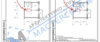
Measuring and determining the size (width) of window openings on a house plan in AutoCAD
Use the “Distance” tool on the classic “Details” toolbar, or from the “Utilities” toolbar on the “Home” tab of the tool ribbon, thereby calling the “Dist” command in AutoCAD. Measure the width of the window opening. Its width was 932 mm.
In the same way, we measure the width of the remaining window openings in the drawing of the plan of the first floor of the cottage. We obtain the width of window openings = 1190, 2080 mm.
Below is a picture of “Width of window openings for residential premises for external walls”. According to GOST data, the sizes of window openings for the plan of our cottage are 910 mm, 1210 mm, 2110 mm.
Basic example
Let's make a blank html page, paste the resulting SVG directly into it and add some CSS so that nothing extends beyond the screen. There’s not even anything to comment on here.
.map { width: 90%; max-width: 1300px; margin: 2rem auto; border: 1rem solid #fff; border-radius: 1rem; box-shadow: 0 0 .5rem rgba(0, 0, 0, .3); } .map > svg { width: 100%; height: auto; border-radius: .5rem; }
We remember that we added classes to buildings and use them to make the CSS more or less structured.
.building { transition: opacity .3s ease-in-out; } .building:hover { cursor: pointer; opacity: .8 !important; } .building.-available { fill: #0f0 !important; } .building.-reserved { fill: #f00 !important; } .building.-service { fill: #fff !important; }
Since we set inline styles in Inkscape, we need to override them in CSS. Would it be more convenient to do everything in CSS? Yes and no. Depends on the situation. Sometimes there is no choice. For example, if a designer has drawn a lot of multi-colored things and transferring everything into CSS and inflating it to the point of impossibility is somehow not comme il faut. In this example, I use the “inconvenient” option to show that it is not particularly scary in the context of the problem being solved.
Let's assume that we have received fresh data on houses, and we will add different classes to them depending on their current status:
const data = { id_0: { status: 'service' }, id_1: { status: 'available' }, id_2: { status: 'reserved' }, id_3: { status: 'available' }, id_4: { status: ' available' }, id_5: { status: 'reserved' }, messages: { 'available': 'Available for rent', 'reserved': 'Reserved', 'service': 'Available in 1-2 days' } }; const map = document.getElementById('my-map'); const buildings = map.querySelectorAll('.building'); for (building of buildings) { const id = building.getAttribute('data-building-id'); const status = data[`id_${id}`].status; building.classList.add(`-${status}`); }
We get something like this:
Something similar to what we need is already visible. At this stage, we have highlighted objects on the terrain plan that respond to mouse hover. And it’s not difficult to add a response to a mouse button press for them using the standard addEventListener.
Frame and title block of the drawing
The next step that needs to be followed, in addition to choosing a format, is creating a frame and title block on the drawing.
Frame
This is a rectangle that limits the field for a drawing of a structure, product or electrical element.
It has its own indentations from the edges of the sheet. So, regardless of how the Whatman paper is located (horizontally or vertically), it is always necessary to retreat 20 mm along the left edge, while 5 mm are set aside on the other sides.
After the internal frame has been drawn, it is necessary to draw the main inscription in the lower right corner, retreating directly from the created frame.
GOST for drawing design offers several types of main inscription. They are selected based on whether the first sheet in the drawing binder is the first or the next one. So, for example, when performing several drawings for one task, the first sheet contains a variant of the frame of form 1.
When decorating the drawing frame for the second and subsequent sheets, the main inscription is smaller in height - this can be form 2 or 2a.
Determining distances
Before we begin drawing up a plan for our home, we need to know the dimensions of the room or the entire home. Previously, tape measures were used for this, but today everything can be made much simpler by purchasing a laser rangefinder, we can simply point it at any wall and find out the distances as quickly as possible. This makes it possible not to waste energy physically moving around the apartment and holding out tape measures, or even moving ordinary meter rulers from place to place. And there is practically no chance of making a mistake.
However, we still can’t do it without a tape measure, since it’s still easier for her to measure the thickness of the walls or the parameters of the room furnishings.
Symbol in AutoCAD for glazing window openings on a cottage plan
Let us conventionally designate the glazing of window openings in AutoCAD by drawing a line at a distance of 120 mm from the outer boundary of the wall. For these purposes, it is convenient to use the “Similarity” command to construct similar objects with an offset of 120 mm, and then the “Trim” command with the “Select all” option to trim unnecessary lines in AutoCAD, where each object is a cutting edge and all objects can trim themselves .