Cables and wires in residential and non-residential buildings are laid from a switchboard with an electricity consumption meter, safety plugs or circuit breakers under the floor, along the walls to distribution boxes, where they are connected by twisting or using terminal blocks (electrical clamps).
From the distribution boxes, electrical wiring is laid to other junction boxes or switch boxes, which are connected to one machine or the same group and to switches, sockets, and lamps. It is possible to make a connection without special education or experience as an electrician; just follow these instructions.
Usually 3–4 groups come to the apartment (including a separate group that comes to the electric stove, which is laid with independent cables or wires). Thus, if there is a fault on the line, only part of the building or apartment is disconnected from the power supply. Pay special attention to the proportional and uniform distribution of the load between the circuit breakers or safety plugs in the electrical panel.
Before starting work, it is necessary to de-energize the line on which work will be performed by unscrewing the plugs or turning off the machine.
As a rule, one distribution box is installed for each room; if the sockets are significantly distant, an additional one can be installed, specifically for the sockets.
Connecting the cable for lighting in a box: How to do it yourself - Instructions + Video
Cable wiring diagrams.
For a residential building that was built in the 60-70s. a simple electric meter, which was installed in the hallway of the apartment, was sufficient. At that time, automatic or more often ceramic plugs were used as fuses. This was enough for low-power appliances, and not everyone had a TV or washing machine. But times are inexorably changing, and almost every apartment has a washing machine, boiler, PC (one or more), dishwasher, etc.
For this reason, they began to install input equipment that is able to withstand the entire load.
General information
Among what will be required for improvement is the selection of elements, installation and disconnection of cables in the electrical panel. I would like to immediately note that to perform such work you need special knowledge and practical skills in electrical engineering. But if you have instructions, ready-made diagrams, an electrical panel and you know all the safety requirements, you can assemble the panel and figure out how to connect the cable cores yourself.
Electrical panel - what is it for?
The distribution panel that is familiar to us, which is installed at the entrance to a private house or apartment, is needed in order to ensure safety when using electrical equipment and devices. In houses of a new type, such panels are already provided, but even in old buildings they are gradually replacing traffic jams and meters. Using a shield, you can intelligently distribute energy between all groups of consumers and create excellent protection against short circuits and overloads.
For placement you will need a plastic or metal box. First, they install an electric meter and a general switch to completely cut off power to the apartment. This shutdown can be done manually, or it will work itself in an emergency (network overload). If an input machine is installed in front of the meter, then it must be sealed (and the meter too).
Of the group of devices, circuit breakers have the most number of devices. They not only protect the wiring, but also the household appliances themselves. For each machine, a group of consumers is defined, and for each powerful device they install their own machine. Thus, you can turn off the devices individually, or the switch will work automatically in the event of an emergency.
In addition to automatic machines, residual current devices are also installed in the panel. They are needed to compare outgoing and incoming currents and are triggered if the balance is upset. This usually happens due to uncontrolled current leaks, and shutdown occurs due to exposure to current that is safe for humans.
And lastly, there are special busbars in the distribution panel, which are made in the form of copper strips. You can connect machines and other devices to them. The neutral wires go to a special block with terminals - the zero bus. To connect grounding, use a grounding bus.
Consumers and their distribution
All electricity supplied to the facility must be evenly and correctly distributed among all consumers.
When distributing and disconnecting cable cores, you must be guided by special rules and regulations:
- Consumers that are considered powerful (from 2,000 W and more) are grouped into different groups. Each group should be connected to a machine that can withstand the load.
- Connect the washing machine and dishwasher, as well as air conditioning and other devices that are not very powerful, to 16 A machines. Please note that the cable cross-section should not be less than 2.5 mm 2.
- Powerful devices (over 380 V) must be connected to 20 Am or 32 Am circuit breakers. In this case, the cable cross-section must be at least 4 mm 2. The cable should not have branches, and it should be laid in whole pieces.
- Connect separate lines to the sockets for each room and, if using a three-core cable, the cross-section of which will be at least 2.5 mm 2. Separate branches are provided for the sockets in the distribution box.
- Lighting devices are also divided into groups and connected to a separate cable, which has a cross-section of 1.5 mm 2 and to a 10 Ampere circuit breaker.
Only at first glance, connecting with cable lines seems like an unnecessary and unnecessary stage of work. The best option is a single-line diagram. It received a self-explanatory name due to the group display of wires. Standard diagrams indicate all the wires that belong to each line. The difference between a single-line diagram is that the total number of conductors is depicted with oblique dashes. At the bottom of the diagram there is a special layout with consumer lines, as well as general markings of power and cable that will be used for installation.
Each device is identified by symbols. H1 is a load switch (switch), with which you can open an electrical circuit that is under load. A circuit breaker can be used instead of this switch, but due to its technical characteristics it does not tolerate switching off under load. The remaining symbols H2, H3 and others correspond to the circuit breaker, and the symbols A1, F2, F3 refer to residual current devices.
For clarity, there are diagrams that show devices and equipment, as well as the connections between them. Near each device you can find marks and denominations.
Features of connecting the power cable to various elements of the electrical network
In the article we will tell you how to connect the power cable to the panel/battery/amplifier/socket, etc., we will look at diagrams and instructions. Industrial enterprises produce a large number of varieties of power cables and circuit elements through which they are connected:
- Distribution boards;
- Sockets, single-phase, three-phase;
- Connectors of various designs for household and industrial equipment;
- Batteries in DC networks and others.
In all cases, there are installation features that are recommended to be followed to ensure high-quality contacts. Reliable connection of the cable with other network elements ensures long-term and trouble-free operation of the power line itself, all its elements and equipment connected to it.
Connecting the power cable to the distribution board
Many factors are taken into account before laying the cable to the distribution board:
- Location of control panel;
- Outdoors, in a dry room or with high humidity;
- Design of the switchboard, installation location of busbars and cable fastening elements;
- Location of input holes on the distribution board housing for cables and other points.
First of all, it is planned from which side the cable will approach the distribution board. In plastic and metal enclosures of the distribution board, the contours of technological holes are stamped in production for cable entry from several sides. This stamping allows you to quickly open the hole from the desired side. Please note that according to the requirements of PUE clauses 1.1.7 and 1.1.8, outdoors in the open air or in rooms with high humidity, cables are installed only from the bottom side of the distribution board. This reduces the likelihood of moisture getting under the outer insulating shell and inside the cabinet.
Cable stripping and connection
Almost all input cables for high current loads have at least double insulation on each core and an outer sheath. Therefore, regardless of what brand of cable, the following operations are performed for installation:
- Ferrule pressed onto the end of a wire
Using a mounting knife, remove the outer insulating layer 150 - 250 mm from the end of the cable;
- Separate the wires; it is recommended to immediately mark the cable and each wire. There are many ways of marking, one of the simplest is to put cambrics on the wires with the appropriate inscriptions. A sticker is glued onto the common shell and wrapped with transparent tape; it indicates where the cable comes from and where, the cable brand, the number and cross-section of cores, and length. Wires of the same color can be marked with colored cambric or electrical tape; this marking is clear to professional electricians. Blue, black color indicates neutral wire, red, brown or white phase, yellow-green ground.
- The cable is inserted into the control panel with a margin of up to 0.5 m for cutting and in case of possible changes in the connection diagram. To do this, near the cabinet it is folded into a loop; if space allows, the loop can be placed inside the cabinet.
- In modern switchboards, holders or crossbars are made for laying cables in vertical or horizontal positions. The cable is secured to the fastening elements with plastic clamps with a lock.
- Inside the cabinet, the cable is mounted towards the busbars or towards the contacts of the input circuit breaker.
- The ends of the wires are stripped of 1-1.5 cm of insulation, tubular lugs of the appropriate diameter are put on them and crimped with a special press.
- The contact tips are flattened on one side and have holes for bolts with which the contact plane is pressed against the busbar or terminal of the circuit breaker.
Connecting wires with lugs to the contacts of the circuit breaker
- Some models of automatic protective switches do not require lugs; the bare ends of the wires are inserted into the contact group and clamped with bolts.
An example of attaching pinch wires with lugs to a busbar
For reliable contact, it is very important that the surfaces of the tips are adjacent to the tires as much as possible. Under such conditions, good current flow will be ensured. Wires with a cross-section of up to 10 mm2 in the distribution board and ASU can be connected to special blocks with clamping bolts, where no lugs are required.
Connecting wires to terminal blocks with clamping bolts
When connecting the cable to the switchboards of a three-phase line, the requirements for laying the cable to the cabinet and inside remain the same, except for the marking, the neutral wire and grounding are indicated by the letter “N” in blue, light blue and “PEN” - yellow-green. The phases are designated by the letters “A”, “B” and “C”. All cables are marked on both sides and the wire designations on both ends must match. Read also the article: → “Marking of individual wires and cable lines during installation work.”
Connecting power cables to outlets
For wiring in the socket group of premises, it is recommended to use VVG cable. In wooden structures they lay VVGng, which has insulation made of non-flammable material; there is an imported analogue of this NYM wire, but it is significantly more expensive.
Tip #1. It is not recommended to install PUNP brand wires; they are convenient for installation, but very rarely correspond to the declared characteristics. This is due to unscrupulous manufacturers, 80% of the products on the market are defective, the percentage of copper in the alloy is underestimated, the insulation layer and wire cross-section are thinner, and there are many other inconsistencies. These shortcomings lead to emergency situations: the cable cannot withstand the calculated current loads, and the wires burn out.
When planning, the maximum power of electrical appliances connected to the socket group is taken into account; the choice of wire cross-section depends on this. Statistics and practical experience show that for an apartment or private house, wires with a cross-section of 4 mm2 are laid between distribution boxes in socket groups. From the junction box to the 2.5 mm2 socket, provided that ordinary household appliances of low power, TV, iron, refrigerator, hand-held power tools and other equipment are turned on.
Connecting the wires of the socket group in the distribution box
In distribution boxes and socket boxes, the cable is inserted to 15 - 20 cm, the outer sheath is removed up to 10 cm, the insulation from the wires is 5 cm in the distribution box, in socket boxes up to 1 cm. The bare ends in the distribution box for connection to the socket are twisted together with two pliers . Both wires are clamped together near the end of the insulation, and near the bare ends. The first ones remain stationary; the second ones make rotational movements to twist a pair or more wires.
In this case, you need to have a sense of proportion, twist tightly, but not overtighten until the twist breaks. In the classic version, the ends of the strands in the distribution boxes are welded with a welding machine, a step-down DC transformer, with a graphite electrode. But most often, installers do not adhere to these technologies; the twists are simply insulated with electrical tape or plastic caps.
Installation and connection
Installation steps
All devices that are mounted in the electrical panel have standardized dimensions, which greatly facilitates installation. For the main fastening, you can use a DIN rail, which is made in the form of a metal profile. Seats are measured in modules. This unit corresponds to 1 unit of space occupied by a single-pole automatic switch.
When calculating the places that will be used in the panel, it should be taken into account that 2 modules are one two-pole circuit breaker, and 3 modules are one three-pole circuit breaker. When installing a single-phase RCD, 2 modules will be required, and for a three-phase RCD, four. One module fits one terminal block, and an electric meter may require from 6 to 8 modules (it all depends on the design).
In general, it is recommended to assemble the shield on a flat, flat surface, for example, on a table. Doing the same thing on a wall will be much more expensive. Be that as it may, strengthening the shield must be done before filling from the inside.
First, install an input device for automatic protection. After this, the cable connection diagram can be made in two versions:
- In a linear diagram, all RCDs are located after the input circuit breaker, and after the circuit breakers. In this case, it will be difficult to find the fault that has appeared on the line.
- According to the group scheme, we first install a common RCD for the group, and only then the machines. In this case, in the event of an emergency, one group will be disabled, and the rest will operate in normal mode.
Installation of devices is carried out according to general rules:
- The wires inside and at the input of the panel must be of the same cross-section.
- Each device must be placed so that there is an entrance at the top and an exit at the bottom.
- Multicore wires can be clamped using NShVI lugs.
- To connect two wires in one terminal, use lugs that are designed for two wires.
Before you start disconnecting the cable, connect all the wires that are components of the entire apartment/house circuit to the electrical panel. Now you can start collecting. All models must be located on a special surface and secured with clamps. If necessary, you can move each device, and thereby be able to free up space for another device. After this, everything is connected with wires, which also need to be prepared in advance.
Connecting wires and cables in the panel
First you need to remove the insulation from the wires. After this, you can start connecting the wires to each other. If you use stranded conductors, then it will be convenient to make everything with lugs with the cross-section you need, the crimping of which is carried out using press pliers.
The technology for disconnecting the cable is much simpler thanks to the use of special tires. They have flat pins that look like pins that connect to the pins. These combs are not produced for all types of devices and will not fit other models due to the different pitch of the pins. Because of this, it is recommended to buy a single set from one manufacturer in order to simplify your work in the future.
Excess wires are cut off, leaving only what is needed for connection. When making connections, you must strictly observe the color markings, which correspond to different cores and conductors. When making connections with violations, you can create all the conditions for a short circuit, fire or breakdown of conductors.
Installation of electrical equipment in a distribution board
There are no standards regulating the installation location of modular devices in electrical panels. There is only one installation rule: the equipment layout must be clear to both other professionals and users. It is advisable to place the input circuit breaker, general protection and measuring instruments in the top row. Place frequently used modules below.
This arrangement of the panel elements allows you to connect the input block to the upper terminals, and the voltage distribution along the lines is carried out from the lower terminals.
All internal equipment of the electrical panel is installed on special DIN rails, which are most often already installed in the housing. Most manufacturers of switchboard equipment complete their products with various useful add-ons. In addition to DIN rails, this list includes various wire and cable clamps, input seals, false panels, as well as special roll-out frames to facilitate equipment installation. We can say that any switchboard housing is initially equipped with everything necessary for installing modules and other devices.
But closer to the topic! We have already decided where to install the main groups of modular devices. The upper part is occupied by the entrance group, followed by frequently used modules. These include group-type RCDs. As a rule, one RCD is installed for each outlet line and additionally for the bathroom and kitchen. Such current protection, together with circuit breakers, makes it possible to avoid installing differential circuit breakers.
If we talk about automatic switches, then the first to be installed are modules to protect lighting lines, then sockets and specially dedicated ones: for a boiler, washing machine, and so on.
Installing circuit breakers, RCDs and other equipment on DIN rails is very simple. The modular device is inserted onto the rail until it clicks; no other operations are required, as it will be securely fixed.
To dismantle or move the equipment, just press the module's eye with a screwdriver - the device can be easily removed from the mounting strip. If it is necessary to install an electricity meter in the distribution panel, it is also installed on a DIN rail. Well, that's all about installing equipment in an electrical panel! It's time to move on to connecting the elements according to the schematic diagram.
Wiring diagram or connection of electrical cables in a junction box
Cables and wires in residential and non-residential buildings are laid from a switchboard with an electricity consumption meter, safety plugs or circuit breakers under the floor, along the walls to distribution boxes, where they are connected by twisting or using terminal blocks (electrical clamps).
From the distribution boxes, electrical wiring is laid to other junction boxes or switch boxes, which are connected to one machine or the same group and to switches, sockets, and lamps. It is possible to make a connection without special education or experience as an electrician; just follow these instructions.
Usually 3–4 groups come to the apartment (including a separate group that comes to the electric stove, which is laid with independent cables or wires). Thus, if there is a fault on the line, only part of the building or apartment is disconnected from the power supply. Pay special attention to the proportional and uniform distribution of the load between the circuit breakers or safety plugs in the electrical panel.
Before starting work, it is necessary to de-energize the line on which work will be performed by unscrewing the plugs or turning off the machine.
As a rule, one distribution box is installed for each room; if the sockets are significantly distant, an additional one can be installed, specifically for the sockets.
Cable connection
Cable termination
Cable termination is a process that allows, through junction boxes, to reduce electric shock to a minimum. Unlike methods such as wrapping with electrical tape or other materials, disconnection is more effective and also safer. Disconnection of cables is usually carried out together with equipment such as lamps, switches, sockets, accompanied by the laying of wires, taking into account the fact that a certain number of devices will be powered from one line. In this process, junction boxes play one of the main functions; there are several types of them, based on open or closed wiring. There are semi-hermetic and sealed, plastic and metal boxes.
Installation is carried out in the most accessible places, based on the technical purpose, as well as parameters, which subsequently does not complicate their service and maintenance. The use of deep-type boxes is not convenient in every case when installing SCS and is most often impractical, since in order to check connections it becomes necessary to dismantle the switch and sockets, which leads to cable breakage. When disconnecting wires, special clamps are used to create uninterrupted contact.
www.alp-scs.ru
Step-by-step guide to installing a junction box
- Insert cables or wires into the box through seals in the holes (for overhead boxes) or through pre-drilled holes in boxes installed inside the wall.
- Fix the box to the ceiling or wall using 2 self-tapping screws or dowels for an overhead installation method, or seal it flush with the wall or ceiling for a hidden installation.
- Carefully remove the outer insulation of the cable right up to the entrance to the junction box. At the same time, it is necessary to maintain the integrity of the internal insulation of the cores. It is good to isolate accidentally damaged areas with electrical tape.
- Adjust the length of the wires or cores, leaving a maximum margin, while taking into account the possibility of laying them inside after completion of the work. Usually a margin of about 15 cm is left. If there are a large number of wires in one junction box, they are shortened to 12–10 cm.
- Strip the ends of the wires or cable cores.
- Connect the cores (wires) according to the operating diagram using terminal blocks (electrical clamps), insulating PPE caps or twisting.
- Insulate the twisted ends with electrical tape or screw on insulating caps.
- Separate the bundles of phase, neutral, and grounding wires to the sides, then carefully lay the wires inside; to make the task easier, you can carefully push them in using the wooden handle of some tool.
- Close and screw the lid.
Learn more about choosing a connection method and features of video editing
Wire connection methods
There are several methods for connecting electrical wires. You can choose the most convenient and suitable option for your case.
Twist
Twist
Currently, connecting cables in junction boxes using the twisting method is prohibited - it is considered extremely unreliable compared to other existing options. By choosing twisting, you consciously accept all possible responsibility upon yourself.
How to properly splice and branch wires using twisting
The connection itself is extremely simple: approximately 10 mm of insulation is removed from the wires, and then they are carefully screwed onto each other. When connecting wires with a diameter of up to 1 mm, we perform at least 5 turns, in the case of twisting more “serious” cables - from 3 turns.
Crimping
Crimping tool
Popular connection option. It is performed using a special sleeve according to the size of the wire bundle. The sleeve material must also match the cable material.
To crimp the product, press pliers are used to crimp the sleeves. Craftsmen often try to perform crimping using pliers, but professionals recommend refraining from this option, because the connection will not be as reliable.
The work is performed in the following order.
We remove the insulation from the wires, focusing on the length of the sleeve used.
We twist the wires into a bundle and insert them into the connector.
We crimp the sleeve with the wires using press pliers.
Crimping process
We insulate the finished connection with heat shrink or regular electrical tape.
Crimping process
Welding
Welding
After making such a connection, you get essentially a solid wire, which is not afraid of either oxidation processes or other negative effects characteristic of detachable methods.
To connect wires using the welding method, you need to prepare the following:
- 24V welding machine with power from 1 kW;
- flux;
- carbon electrode;
- protective equipment (gloves, mask/goggles).
Wire welding diagram
We work in this order.
We remove the insulation from the cables and strip the conductors until they shine. To do this we use sandpaper.
We connect the wires using the twisting method.
We pour flux into the recess of our electrode.
Twist welding machine TS 700 2
We turn on the welding machine, press the electrode against the cables and hold it until a ball forms - the so-called. "contact point".
Welding
We clean the resulting contact point from flux and cover it with varnish.
Finally, all we have to do is insulate the finished connection.
Soldering
Soldering
The procedure remains the same as when connecting wires by welding. The only difference is that the cables are connected using solder melted with a soldering iron. The molten solder should flow into the twist.
It is also not recommended to use soldering in areas of possible mechanical stress on the connection.
Screw terminals
Screw terminals
A great method for quickly and easily connecting wires in a junction box. Compact, inexpensive clamps allow you to connect both homogeneous and dissimilar conductors.
The job is done in two simple steps. You need to do the following:
- strip off approximately 5 mm of insulation from the ends of the wires;
- insert the wires into the clamp and tighten with a screw.
Bolted connections
Bolted connections
Termination of wires
The connection is reliable, but very bulky. Suitable for the same bulky old-style boxes. In a modern box, a bolted connection may simply not fit.
The work is performed in the following order.
We put a steel washer on the bolt.
We put one of the wires to be connected on top of the bolt. First you need to peel off the insulation and form a ring from the cable. We do the same with the second wire in advance.
We put on the next steel washer.
We put on the ring of the second wire. Fifth step
We put on the last washer and tighten the connection with a nut.
Of course, a bolted connection also needs insulation, which will not have the best effect on its dimensions.
Methodology for using RCD
Self-clamping connections
The most modern and popular option today. The clamps are extremely easy to use. In addition, such connections initially contain a paste that eliminates the risk of metal oxidation, which allows dissimilar conductors to be inserted into the clips without any fear.
We work in this order.
Self-clamping connections
First step. We remove approximately 10 mm of insulation from each wire.
Second step. Raise the clip lever up.
Third step. Insert the conductors into the connector.
Fourth step. We lower the lever down.
Clamps without levers simply snap into place.
Self-clamping connections
Distribution box wiring diagram
All protective or grounding (marked as PE in the diagram, highlighted in yellow) and neutral conductors (marked N in the figure, marked in blue) are connected to each other by color, as shown in the diagram. There will be no ground conductor if the wiring is two-wire.
Phase conductors (highlighted in black and red) are a little more difficult to disconnect; if the wiring from the distribution box goes only to the sockets, then the phases are also connected to each other.
In the case when the wiring goes to a lamp with a single-key switch (as shown in the figure), the wire that comes from the switch is connected to the phase going to the lamp (in the picture L to lighting), and the phase coming to the switch is connected to all phase wires (on the diagram L for the switch). There should be 4 connections.
When distributing conductors to a luminaire with a two-key switch, a four-core cable is laid before it (2 on-phase conductors, 1 off-phase, 1 neutral, 1 “ground”). In the case of two-wire wiring, it is three-wire, since there is no ground conductor. The phase conductors going to the sockets are connected to each other. The phases of the power cable coming to the common terminal of the two-key switch are also connected, 2 wires from which go to the lamp lamps separately. Below are wiring diagrams for a two-key switch without ground.
All neutral and grounding conductors (if the latter are present) are connected together. There should be 5 connections inside the box (including the connection of the grounding conductors). Below is a wiring diagram for a two-key switch with ground.
Switching off the electrical panel
In older residential buildings, until recently, a conventional electric meter installed at the entrance was sufficient. The function of fuses was performed by ceramic or automatic plugs. For a small number of low-power household appliances, this was enough, and consumers did not experience any problems. Currently, the situation has changed radically. Powerful equipment appeared in the apartments, which required a completely different input. Therefore, in the new conditions, great importance is attached to the correct equipment of the input device. The list of activities includes the selection of components, installation and disconnection of the electrical panel.
- What is an electrical panel for?
- Consumer distribution
- Drawing up an electrical panel diagram
- Installation of components
- Connecting cables and wires inside the panel
What is an electrical panel for?
The distribution panel installed at the entrance of an apartment or in a private house primarily ensures electrical safety during the operation of devices and equipment. In new buildings, they are initially provided for by the design, and in old buildings, panels are gradually replacing meters with plugs. With the help of a switchboard, electricity is distributed between groups of consumers, and reliable protection against overloads and short circuits is created.
A metal or plastic box is used to place electrical appliances. It is mandatory to install an electric meter and a general switch to completely de-energize the apartment. Shutdown can be done manually or it will happen automatically when an emergency occurs. If the introductory machine is installed in front of the meter, then it is subject to mandatory sealing, just like the meter itself.
The most numerous group of devices are automatic switches. They protect not only the wiring, but also the household appliances themselves. Each machine corresponds to a specific group of consumers, and an individual machine is installed on each powerful device. Each of them can be forced to turn off or work automatically.
In addition to automatic machines, residual current devices are installed in the panel. They compare the incoming and outgoing currents, and if the established balance is violated, they are triggered. As a rule, this happens due to uncontrolled current leaks, and the shutdown itself occurs under the influence of a current that is safe for humans.
The electrical panel contains special busbars made in the form of copper strips. Machines and other devices are connected to them. The neutral wires are connected to a separate block with terminals - the neutral bus. To connect the grounding, a special grounding bus is used.
Consumer distribution
All electricity supplied to the facility must be correctly and evenly distributed among existing consumers. When carrying out the distribution process, you must be guided by special norms and rules:
- Powerful consumers of 2 kW and more are combined into separate groups. Each of them is connected to an automatic machine capable of withstanding the specified loads.
- Dishwashers and washing machines, as well as air conditioners and other low-power appliances are connected to 16 A machines. The cable cross-section must be at least 2.5 mm2.
- Devices with higher power (380 V) must be connected to 20 or 32 ampere circuit breakers. The cable cross-section accordingly increases to 4-6 mm2. These cables should not have branches; they are laid in whole pieces.
- The sockets are supplied with separate lines for each room using a three-core cable with a cross-section of 2.5 mm2. In the distribution boxes, individual branches are provided in the direction of the sockets.
- Lighting devices are divided into groups and connected to a separate cable with a cross-section of 1.5 mm2 and to a 10 A circuit breaker.
Connecting with separate cable lines seems unnecessary only at first glance. In fact, this is the only way to ensure electrical safety and ease of use. In the event of an emergency, only one group of consumers is disconnected, and not the entire network. In this case, troubleshooting is greatly simplified.
DIY electrical wiring installation
It is customary to begin laying electrical wires immediately after the walls and roof are erected. To do this, you can call an electrician or do everything yourself. If the concept of “electricity” is not something scary and incomprehensible, then the second option will allow you to save a little on building your house. You just need to have basic skills in handling a hammer drill, pliers and a screwdriver, and also not forget about proper safety measures.
Typical wiring diagram for a private home
However, if you have doubts about your own competence in this matter, then it is better to entrust the installation of home electrical wiring to a professional. The cost of a mistake here is too high; a fire caused by a short circuit can destroy the entire cottage. You should install electrical wiring yourself only if you have clear confidence in your own abilities and knowledge. In this case, all wiring diagrams and selected wires must comply with electrical installation standards and regulations.
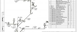
Drawing up an electrical panel diagram
At the next stage, you can proceed to drawing up a diagram. The most optimal would be a single-line option. This circuit got its name because of the group display of wires. On conventional diagrams, all the wires associated with each line are drawn. On a single-line diagram, the number of conductors in groups is depicted by inclined transverse lines. At the bottom there is a layout with consumer lines, indicating their power and cables used for installation.
All devices are identified by special symbols. H1 is a load switch or switch that opens the electrical circuit under load. Instead, it is possible to use a circuit breaker, but it does not tolerate switching off under load due to its technical characteristics. H2, H3, H4... etc. correspond to circuit breakers, symbols A1, F1, F2, F3 – residual current devices.
At the top left there is a switchboard for the entire floor with a 100 A input circuit breaker, an electric meter and an input fire protection RCD that is triggered by high differential currents in the range of 100-150 mA, which can cause a fire. For these purposes, a selective RCD is usually selected, which does not operate instantly, but after other devices located on the line closest to the emergency location. If for some reason they do not work, then a selective RCD comes into effect, shutting down the entire facility.
This diagram looks more clearly as in the figure. All devices and equipment and their connections to each other are displayed here in the same way. Next to each device there is a mark with its rating.
Installation of components
All devices mounted in the electrical panel have unified standard dimensions, which greatly facilitates their installation. The main fastening is a DIN rail made in the form of a metal profile. Seats are measured in modules. This unit corresponds to one space occupied by a single-pole circuit breaker.
When calculating the number of places that need to be provided in the panel, it is necessary to take into account that two modules correspond to a two-pole circuit breaker, and three modules correspond to a three-pole circuit breaker. A single-phase RCD requires two modules, a three-phase one requires four. One terminal block occupies one module, and an electric meter may require 6-8 modules, depending on its design.
It is recommended to assemble the shield in an apartment on a flat and level surface, for example, on a table. Performing this procedure on the wall is much more difficult and inconvenient. In any case, the mount for the shield is installed even before it is filled with equipment.
The input automatic protection device is always installed first. Further, the schematic diagram can be implemented in practice in two versions:
- The linear diagram assumes the location of all RCDs after the input circuit breaker, and behind them there are automatic circuit breakers. In this case, it is very difficult to detect a fault on the line.
- Group scheme. First, a common RCD is installed for the entire group, and then the machines are installed. In this case, in the event of an accident, only one group is switched off, while all the others continue to work.
Installation of devices is carried out according to general rules:
- The wires at the input and inside the panel are used with the same cross-section.
- Each device is located on the panel so that the entrance is at the top and the exit at the bottom.
- Multicore wires are clamped using NShVI lugs.
- To connect two wires in one terminal, special lugs designed for two conductors are used.
Before proceeding with the disconnection, it is necessary to connect all the wires that are components of the general circuit of the apartment or private house to the electrical panel.
After preparation, you can proceed directly to assembly. All modules are placed on a DIN rail in accordance with the developed diagram and secured with clamps. If necessary, each device can be moved to the side to make room for the next device. After this, all devices are connected to each other by wires, which also require preliminary preparation.
Wiring the electrical panel: installation and diagrams
Electrical panel installation
There are many types of electrical panels with different sizes. The size of the panel is selected taking into account the number of electrical appliances that need to be placed in it. The electrical panel contains a zero bus, a protective grounding bus, a Din - rail for installing automatic machines, an RCD, and a voltage relay.
Switching off the electrical panel
Separately, below the rows of machines there is a special cable duct with slots for the cable cores to exit. If the switchboard box is metal, then there should be a welded bolt with a nut inside it to connect the protective grounding. A grounding bolt is also installed on the switchboard door.
At the bottom of the box there are holes for cable entry. These holes are equipped with plastic bushings to protect the cable insulation from mechanical damage. The left hole is usually used for the input cable.
The din rail is cut to length depending on the number of installed machines and protective equipment. After installing the DIN rail, all the necessary machines and a meter are attached. Several machines are installed in the switchboard for different groups of lighting and sockets. If the load is light, you can combine rooms using a separate machine.
Busbar for circuit breakers
For powerful household appliances - an electric stove, a boiler, an air conditioner and others - separate machines are installed, and a separate cable is laid to the sockets of these appliances. One RCD is installed after the 300 mA input circuit breaker or for each group of loads, where a separate RCD is installed after the circuit breakers. Expensive, but reliable. The owner of the house decides which version of the electrical wiring diagram to choose.
Do-it-yourself wiring in the electrical panel
Before you start disconnecting the electrical panel, you need to properly insulate the suitable power cable. This cable is the last to be connected to the input circuit breaker when the connection of the circuit breakers in the electrical panel is completed. The input machine is installed on the DIN rail on the left first.
Ferrules for stranded wire
Next comes the voltage relay, RCD and group circuit breakers. If a wiring diagram for an electrical panel with an RCD is used for each machine, then these RCDs are installed under the machine on the lower DIN rail in the second row. Having completed the installation of all machines, they begin to disconnect the electrical panel. The next step will be to disconnect the jumpers.
From the output of the input circuit breaker (lower terminals), a jumper is placed on the upper terminals of the circuit breakers of the first group, then from the same upper terminal there is a jumper to the next circuit breaker of the panel. The 380 wiring diagram for circuit breakers in an electrical panel differs in that from each phase (lower terminals of a three-phase circuit breaker) there is a jumper (loop) to its individual group circuit breakers.
All three phases on group machines are distributed so that the load is approximately the same. If the general RCD is located after the electric meter, then the phase wire of the meter is connected to the upper terminal of the RCD “L”, and the neutral wire from the electric meter is also connected to the “N” terminal. Now the phase wire from the lower terminal of the RCD is disconnected by a loop to the upper terminals of the group circuit breakers.
An example of a wiring diagram in a house with one common RCD
And from the output terminal “N” of the RCD, a jumper is placed on a separate zero bus. If several RCDs are installed for separate groups of loads, then they need to be placed under their own machine of this group. The phase from the group circuit breaker is connected by a jumper to the upper phase terminal of the RCD “L”, and the neutral wire is taken from the neutral bus and connected to the upper terminal “N” of the RCD.
A cable leading to its group of sockets and lighting is connected to the lower terminals of the RCD. For the convenience of disconnecting the electrical panel, special busbar copper conductors are used. They are connected to the upper terminals of the machines instead of jumpers and represent a loop of copper busbars. The load cables are laid in such a way that the longest end of the cable lies in the cable channel to the last machine (on the right).
Electrical wiring diagram with RCD for the group. An RCD is also installed for other groups
The next cable will be a little shorter and the last one will be very short, it will go to the nearest left machine and will be at the top. Now all the cables in the cable channel can be secured into a bundle with plastic clamps. When connecting cables to machines, a small supply of wires is left, which are laid in the cable channel.
The loads are connected with a three-core copper flexible cable. The colors of the insulation of the cable cores should be for the phase - these are white, gray, brown, etc., - for the neutral conductor - these are blue, light blue, - for protective grounding - these are yellow - green. The insulation is removed from the ends of the copper flexible cable and special tips are put on, selected according to the cross-sectional size of the cable cores.
These lugs are inserted under the machine terminals so that the non-insulated part is completely crimped by the machine terminal. Wires and cables are laid vertically or horizontally, or bent at right angles. Finally, all cables need to be marked and a wiring diagram drawn up, pasted on the inside of the electrical panel door.
electricavdome.ru
Connecting cables and wires inside the panel
At the first stage, the insulation is removed from the current-carrying conductors. After this, the wires are connected to each other. For stranded conductors, special lugs with the required cross-section are used. They are crimped using press tongs.
Disconnection of the electrical panel is greatly facilitated by the use of special tires. They have flat pin-shaped contacts that connect to the contacts of automatic devices. Such combs are produced for specific devices and are simply not suitable for other modules due to the difference in pin pitch. In this regard, it is recommended to purchase the entire set of equipment from one manufacturer to facilitate installation.
Excess wires are cut off, leaving only the necessary margin for connecting the equipment. When disconnecting the wiring, the color marking corresponding to the phase conductors, neutral and grounding conductors must be strictly observed. An incorrect connection can lead to a short circuit, fire or breakdown of individual conductors.
Exclusion what is it
Disconnection of the distribution box (Wiring) is carried out by an experienced specialist. According to the PEU, electrical connections of wires should be made only in junction boxes.
By contacting Efas LLC, you can be confident in the reliability, quality, and durability of this work. We provide a 5-year warranty on the wiring of junction boxes . Very often you can find a poor-quality connection of wires, which can cause a fire, or simply a loss of voltage in an apartment, house or workplace. Remember that now there are a lot of “specialists”, but not many will perform high-quality wiring of the box .
Connecting a lamp with a two-key switch
Connecting to a double switch is carried out in almost the same way as a single-key switch. In fact, these are two single-key devices placed in a common housing. You can also connect two light bulbs to one switch.
Before installation begins, you need to find out where the contacts are located. Sometimes their circuit is located at the back of the device. Double devices have three contacts - a common input and two separate outputs. The input comes from a phase wire from a distribution box or from a socket. Two terminals control the light bulbs located in the luminaires. During installation, the input is located at the bottom, and the terminals are located at the top. This connection is clearly shown in the diagram presented.
A three-key switch is connected in exactly the same way as connecting a double switch, only one more terminal and an additional terminal are added to it in the distribution box.
Number of blocks: 8 | Total number of characters: 9317 Number of donors used: 3 Information on each donor:
Box wiring
Disconnection of distribution boxes is carried out in several ways: Soldering, crimping, welding, using terminals, clamps. All these methods can be used when disconnecting junction boxes . The most reliable method is crimping and welding, but this takes more time and requires special equipment and experience.
Network switching
Switching is the process of switching in electrical circuits when different sections of the circuit are closed or opened. Each element of the electrical circuit (socket, switch, lamp) is combined into a distribution box . Then in this junction box it is necessary to connect the wires in the required ratio so that the switch is a switch and not a socket and vice versa. To do this, you need to be guided by the PUE.
Installation
The junction box is installed on the wall with a lowering of 10–30 cm from the ceiling. Moreover, this is done in such a way that there is open access to its lid. Checking the condition of the wires should be carried out on a regular basis.
Step-by-step instruction
Installation of the junction box is carried out in four simple steps:
- Fastening the box to the wall according to the wiring diagram.
- Planting wires inside and then connecting them to each other.
- Checking the assembled electrical network.
- Closing the electrical installation product with a cover.
The junction box is secured using self-tapping screws or plaster (if it is recessed into the wall).
Arrangement of input cables in the box
Wire connection methods
According to the PUE, the electrical wires inside can be connected:
- twisted;
- soldering;
- welding;
- terminals;
- crimping.
How to properly connect wires in a junction box
Twist
Twisting is the fastest and at the same time the most unreliable way to connect indoor electrical wiring. To cover the exposed wires, special plastic caps or electrical tape are used.
Twist connection method
Soldering
Soldering is done with tin on top of the pre-twisted wire. This connection is much more reliable and durable. However, such installation takes a lot of time.
Welding wires
For welding you need an inverter welding machine. This method is even more reliable and more complex, but as a result, the two connected cores actually turn into a single solid one. It is recommended to choose it only in special cases. For example, when grounding is done in a private house under a powerful load or additional pumps and uninterruptible power supplies are connected for a gas boiler.
Terminal connection
If the wires are made of different materials, then it is best to use terminals with screw or spring clamps. The terminal connection is extremely simple to make, you only need a screwdriver
The most important thing here is not to overtighten the clamping bolts.
Terminal connection of wires
Crimping
When crimping, press pliers and sleeves are used, made of the same metal as the cores, and sized to match the thickness of the wires being connected. Some craftsmen use pliers for this, but such connections are rarely reliable. It's better not to experiment.
Crimping connection method
Wiring diagrams
To avoid any confusion when connecting electrical wires, it is worth preparing in advance the wiring diagrams for all installed junction boxes. This drawing should indicate “from where and where” each core goes. In general, it is advisable to use different colored wires to avoid confusion.
Wiring diagram
Wiring in the box
The basic pattern of actions for unsoldering wires.
— We run the cable into the distribution box (from sockets, switches, lamps, power lines)
— Cut off the excess cable length (leave about 15-20 cm)
— Remove the top layer of cable insulation to the base of the box
— We remove the insulation of the wires of the required length (approximately 1.5-2 cm for Wago type terminals, 5 cm for twisting)
— We connect the wires according to the diagram
— Place the connections in the junction box and close the lid
Here is an example of a standard diagram
Switching diagram
When disconnecting boxes, follow the electrical diagram. As a rule, a standard three-core cable has the following colors: white, blue, yellow-green, where
white-phase conductor and designated as “L”
blue is the neutral conductor and is designated as “N”
the yellow-green-grounding conductor is designated as “PE”
The most optimal method when disconnecting boxes is twisting using a PPE CLAMP (self-insulating clamp), it will maintain the twist in a reliable connection under maximum loads.
Installation of wiring in an apartment or private house: stages of work and step-by-step instructions
Any work, especially electrical installation, must be carried out in strict compliance with a certain algorithm. Everything must be done step by step, and not rush to perform any actions without completing the previous ones. Having made a diagram of the electrical wiring in the house with your own hands, we do the following step by step:
- We calculate the cable cross-section.
- We carry out marking and gating.
- We lay the cable in channels and perform switching in distribution boxes.
- We make connections in the distribution board.
Connections can be insulated using special caps
Let's look at these actions in more detail.
What cables to use for wiring in an apartment or private house
Information on the choice of section has already been provided in our article, and therefore we will not consider the issue again. As for the number of cores, for single-phase systems without grounding, a two-core cable is used, and if there is a circuit, then a three-core cable. For three-phase without a circuit - 4 wires, and with grounding, five-core products are used.
Marking walls according to the electrical wiring diagram in the apartment
Before wiring the apartment, you should correctly mark the cable routes and the location of power points. Having a diagram in front of your eyes, this will not be difficult to do. To speed up and simplify the process, it is better to use a marker cord for marking routes. Although, if you have a laser level with a tripod at hand, you can use that.
The laser level is also very convenient when marking walls
Features of installing hidden and open wiring in the house with your own hands
Along the marked routes, it is necessary to secure cable channels of the appropriate size for the wire using self-tapping screws or make grooves for laying wires. At intersections (branches to sockets and switches) distribution boxes are installed. Their size should be selected based on the number of connections that are planned to be made in them. When installing hidden wiring, it is necessary to use special crowns, with which a hole is drilled for socket boxes or round junction boxes. For square ones, a punch hammer is used.
Brief step-by-step instructions for installing wiring in an apartment
Let us analyze the information presented in general terms using photographic examples.
| Illustration | Description of action |
| Having completed the markings, we make grooves and recesses for installing distribution boxes, sockets and switches. All lines must be strictly vertical or horizontal. | |
| We install plastic boxes and socket boxes. Previously, it was allowed to install metal ones, but now the PUE prohibits this. | |
| We stretch the cables separately for each group. The work is carried out in stages with mandatory marking of the direction of the wire. | |
| When making connections in a distribution box, it makes sense to note where each wire goes. This will help in the future when making repairs. | |
| The laid cables will look like this. Now all that remains is to plaster the walls and do the finishing touches. | |
| The entrance panel in the apartment. It will have a similar appearance when the main power panel is located on the staircase. |
Exclusion what is it
Without the modern benefits of civilization, be it gas, water, the Internet, and especially electrical energy, humanity very quickly returns to its primitive state, when significant efforts are required to achieve any result. Without electricity, none of the usual appliances will work at all; without it you can’t iron, wash, go online, sometimes even cook food. Electricity enters the house from external lines, bypasses the general apartment electrical panel, and then “spreads” through a system of distribution boxes throughout the entire house wiring.
Why are power lines built this way? Is there a rational need for this or is it just a whim of aesthetes who don’t like the look of bundles of twisted wires? What is difficult about the correct wiring, and how does switching wiring affect the overall safety of the home, as well as the uninterrupted supply of electricity?
We will try to answer these and other important questions as fully as possible in this article.
Junction box
The first and most important task of this relatively small PVC box is to minimize the fire hazard. Cable connection points always pose the greatest risk. Contacts tend to weaken over time, and wires and their insulating coating wear out, so cable networks can overheat, the insulation on them melts, even leading to fire, especially if the walls are made of flammable materials. The junction box in this case plays the role of a kind of insulator, which separates numerous connections from the environment.
The second important function of this compact device is to provide almost instant access to the contact connections of all house electrical wiring. If an electrical circuit break or short circuit occurs, it is easy to track in which direction the fault should be looked for and promptly restore the damaged area. In addition, manufacturers produce quite attractive-looking junction boxes of various shapes and colors, so you definitely shouldn’t “sew” them into the walls, creating potential problems for yourself in the future. Despite the small dimensions, quite a lot of bundles of wire connections fit inside the boxes.