A batch switch is the simplest type of device for turning off/on electricity. This is a switch, familiar from Soviet times at the entrance to the apartment in the switchboard. Often also used in electrical installations, control panels, where a manual control principle is required. For homes, the device is positioned as less modern, without the function of protecting wiring or auto-de-energizing during overloads. Nevertheless, packages fulfill their tasks, which is why they can still be found in electrical panels of houses. Replaced with modern and compact automatic circuit breakers (CBs) with a protection function.
Batch switch
Until recently, switches and package switches were used to switch the electrical system manually.
Now this is all done automatically. The equipment is used based on the voltage supply power:
- 100 A – 220 V;
- 60 A – 380 V;
- 440 – 660 V.
The batch switch is a mechanism with a rotating device in the form of a lever. The device is produced in the form of a small container with a handle and terminal leads. The inside of the device is filled with contacts and switching mechanisms.
The body part itself consists of insulated washers connected by bolts. In old houses there are still samples produced in the USSR.
When will replacement be required?
The service life depends on how the locking washer looks. This is the main part of the switch; if it fails, the device requires replacement.
Packet switches cannot be repaired. If damaged, immediate replacement is required. But you won’t have to debug the device throughout the entire period of operation.
Despite the decline in popularity of such models, manufacturers still delight with new developments. Each time the products are improved and shortcomings are eliminated.
And if package switches are less common in everyday life, then in production you simply cannot do without them. Compactness and ease of installation, resistance to damage, ease of maintenance are the main advantages of the package switch.
It is worth paying attention to the models: Legrand (France), Iek (Russia), ABB (Sweden, Switzerland). The products of these companies are characterized by reliability and quality
Device feature
The principle of operation of a batch switch is to disconnect the contacts. The device is installed indoors in special boxes. Designed to shut off electricity from the drive entering the room. The circuits are switched only manually.
For turning off the power supply in production, this is simply an ideal option. The batch switch is turned off manually by turning the switch in the panel.
- Working with the device will not take much time. The main thing is to know the symbols on the device, where < > means on, <> means off.
- When the circuit is closed, the switch is turned by 90 C, leaving it at the <> mark; when opened, the device is set to <>.
- According to GOST, the equipment is designated as a circuit disconnecting mechanism with the required number of poles that are connected mechanically.
When will replacement be required?
Packet switches cannot be repaired. If damaged, immediate replacement is required. But you won’t have to debug the device throughout the entire period of operation.
Despite the decline in popularity of such models, manufacturers still delight with new developments. Each time the products are improved and shortcomings are eliminated.
And if package switches are less common in everyday life, then in production you simply cannot do without them. Compactness and ease of installation, resistance to damage, ease of maintenance are the main advantages of the package switch.
It is worth paying attention to the models: Legrand (France), Iek (Russia), ABB (Sweden, Switzerland). The products of these companies are characterized by reliability and quality
What are they for?
Purpose of this device:
- Boxes for electric machines. Control the load by turning off the network;
- At substations. For control panels. Convenient reading;
- For electric power equipment. Monitoring the activities of cranes and excavators.
Cable Requirements
You can already understand that not every cable is suitable for connecting such equipment. This is logical, since under heavy overloads it will simply burn out and can cause equipment failure or a fire. Therefore, when choosing a cable for an electric stove, you should rely on the following important characteristics:
- Rated voltage;
- material that serves as the basis for wire cores;
- cable section;
- ease of connection to the device.
If we take the rated voltage for devices of well-known brands, then its value must be exactly no less than that provided by the conventional electrical network where the device needs to be connected. Now let's say a little more about the described indicators.
Probably one of the most important aspects that will play a role is the material used to make the cable cores. It's best if they are copper. This metal itself can be soldered if necessary. And the copper power wire is more flexible than its aluminum counterpart. But the cost of a copper solution will be higher. If the choice falls on an aluminum analogue, then you need to understand that its installation should not be carried out in materials that burn. You can find out what the electrical wire is made of thanks to special markings on the product itself.
If we talk directly about numbers, then, as a rule, most solutions from well-known brands (Samsung or Electrolux) are designed for electricity consumption of just under 4 kW. For this reason, the safety margin of the wire needs to be selected based on power somewhere with a focus on this indicator.
To ensure that the device operates as safely as possible, you should also pay attention to the following points:
- If you need to lay the cord directly from the panel to the electric stove, a cord with a standard cross-section of 1.5 square meters is sufficient. mm.
- If other electrical appliances will be connected between the device and the panel, then you should have a cable with a cross-section of at least 2.5 square meters. mm. This option will provide the necessary reserve in case of connecting some other household appliances.
Another important parameter is the phase connection. It will depend on the number of cores in the cable. The wire can be 3 or 5 wires. The number of cores will depend on the power supply network in the room. And it can be either 1-phase or 3-phase. If the first option, then you will need to purchase a wire with three cores, and if the second - with five.
You should also find out whether the purchased equipment supports the type of connection that was selected. For example, stoves with a power of up to 5 kW are usually connected to a 1-phase network, while more powerful ones have a 2 or 3-phase connection. The type of cable that can be used will also be important, but more on that below.
Nuances of the device
The main feature of the package switch is that it is a manual device. To turn the device off and on, a handle is used, which requires considerable force to start the bagger to work.
Mainly used in commercial establishments that require a manual method when switching the instrument.
The bagger can still be found in old houses. In new homes, circuit breakers are already in full use.
Which device is better
When choosing between a packager and an AB, you should give preference to a circuit breaker. Because the AV itself will react in case of network overload (automatic shutdown) and can be switched manually (open circuits).
Comparative characteristics of these two devices:
- Batch switch. It is a device that performs only switching. Switching the device only manually. Attached to the shield body with screws;
- AB. Protects the network from any overloads. Consists of a thermal and electromagnetic device. Turns on manually. It turns off without the use of automation and mechanically. Fastening - on a DIN strip by snapping and using screws.
Why change?
If the question is whether it is worth changing to AB, even if the switch is working, then the answer is unequivocal - yes. This is not only recommended and desirable, but also, one might say, mandatory for the following reasons:
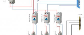
- protection can only be provided by AB;
- connect another automatic protective shutdown device (RCD, RCBO), which is mandatory, for example, in the absence of grounding, when using boilers (powerful electrical appliances) in the house, and, however, it is always, of course, more expedient and convenient with AV;
- if there is a DIN rail, then the modular placement of AB, RCD, RCBO is extremely convenient, although there are shields with it bolted to the box body.
What types of devices is divided into?
Types of package switches are presented in the list below:
- Open devices. They have the first level of protection. They are installed exclusively in dry spaces, avoiding even the slightest presence of moisture and dust. Such devices require iron boxes and shields;
- Protected devices. Does not require installation in the electrical panel area. The bag is located in a plastic device. This eliminates any ingress of dirt and water;
- Sealed devices. They are made of aluminum alloy, providing the best protection for a package switch. The devices are not afraid of moisture and open spaces.
Connection diagram
Packers were developed for use as input switches. Based on this, it is advisable to install them in front of the electric meter, so that if necessary, the entire apartment network can be disconnected. These devices do not protect electrical wiring and equipment from short circuits. For these purposes, circuit breakers are used.
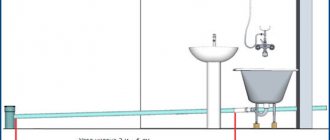
Figure 4 shows an example of a wiring diagram in a one-room apartment, clearly demonstrating the principle of connecting a packet switch.
Rice. 4. Connecting a packet switch
Of course, instead of a batch switch, you can use an input circuit breaker, but this is not advisable. Firstly, it is expensive, secondly, such devices wear out quickly with frequent load outages, and thirdly, the machine may work if a short circuit appears in one of the circuits. Then the entire house or apartment will be left without electricity. The problem is solved by accurate calculations and adjustments of the settings of the input machine.
How to connect a packet switch
The package switch circuit looks like this: instead, the devices install an automatic switch just in front of the meter, de-energizing the network for working with the meter. AB has its own nuances when connected to a single phase of the meter.
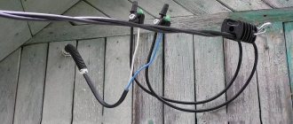
To begin with, the wiring is protected and secured in the screws of the chipping system. In this case, the wires are moved a certain distance from each other or their ends are rolled into rings. Important! The batch switch is connected only to a conductor break.
If there is grounding, the packager is connected by a zero drive. Which is not a working cable.
The three-phase network is special in that AB has two positions. First, the phases are in a closed or open state, the wires are connected to the terminals on one side, observing the correct phase order. Second, the load wires are attached on the opposite side, observing the diagonal opposite.
It is important to remember that package switches are needed where frequent power changes are required. The device will last quite a long time with an average number of starts and switches.
Purpose
Manually controlled switching devices are designed to turn on/off small load currents.
They apply:
- in AC and DC networks, performing the functions of input switches;
- in switchgears for the purpose of distributing electricity in various electrical installations;
- as manual switches for remote control of asynchronous electric motors.
- Package switches are indispensable at substations, where they are used for the purpose of switching measuring instruments. They facilitate the control of electric power units in electrical circuits, which simplifies the work of drivers.
Previously, package switches were located in each of the distribution boards of an apartment building. Their purpose is to manually cut off power during repair work or when servicing lines.
Despite the displacement of package switches by modern automatic machines, they can often be seen in an apartment electrical panel among more advanced switching electrical devices used for protective disconnection of load wires. This is facilitated by the low price of switches and the ease of their maintenance.
Various models of cam switches can be found on load transfer panels. With their help, it is convenient to remotely control electrical mechanisms.
Advantages
- The advantages of packages include:
- compactness;
- high speed of electric arc suppression;
- minimum care requirements;
- resistance to mechanical damage.
Flaws
The devices cannot withstand frequent switching of increased loads. If they fail, they cannot be repaired. Packers are not capable of protecting electrical wiring from short circuits; they are not sensitive to differential currents, which limits their use as protective devices.
Device marking
The markings of bags vary significantly and are indicated by special symbols. Which looks like this: XX X – XXX XX XX XXXX XXXX.
Explanation of symbols:
- XX indicates the type of device;
- PV – switching off the packager;
- PP – device switch;
- X denotes the pole system;
- XXX. Maximum voltage value;
- XX. Switch designation with circuit directions. They are designated –H 2-H 4;
- XX indicates the temperature at which the device can be placed according to GOST 15150;
- XXXX. Indicates the security of the equipment body and the material of its manufacture;
- IP00 indicates that no protection is needed;
- IP30 indicates the degree of protection with a carbolite body - car.30;
- IP56 denotes the degree of protection with a housing made of non-flammable material - card. 56;
- XXXX. Batch switch;
- Climatic norm (U 1). Attached with a front bracket behind the panel part up to 4 mm. Devices with such mounting are used in temperate climates in open spaces;
- Climatic norm 2 (U 2). Attaches with front bracket behind panel up to 25mm. The devices are installed under canopies;
- Version 3 is attached with a rear bracket inside the cabinet. Such fastening is necessary for apartment buildings;
- Design 4 means that the device is protected. Attached using the provided parts in the device. The devices are used in unfavorable climates.
Automatic backup
Sometimes they install a backup machine, but this is not necessary, especially when the line is further protected by an RCD+AV or RCBO. If you decide to install such a device, then you are guided by the standard rule: the optimal rating is less than that of the main device and more than that of group switches further down the line (for example, if there are RCD+AV combinations to protect the boiler, etc.). Example: the main device is 32 A and the backup device is 25 A, if the group devices are 20 A. If such a ratio is impossible, then at least the value should be no lower, that is, correspond to the input AB. In this case, the backup will have the role of a disconnecting device (during line repairs); in emergency conditions, it will snap off simultaneously with the main device.
What to do first
You bought a certain number of wires from the network of a new house, completed the wiring, its ends are connected to a control panel that has not yet been built into the wall, and there are automatic machines nearby. Remember: it is better to install one automatic packetizer or RCD at the entrance to the electric meter. There is no such thing as too much protection. Next, make a plan for connecting the wires to the arranged packages.
It is advisable to relieve the network by dividing it into zones - with heavy loads and normal ones: kitchen, living room-bedroom, corridor-toilet, veranda-basement. You will get confused with packets; the instructions for them describe currents, loads, and wiring cross-sections. Methods of contact with terminals and so on.
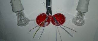
Control of two lighting systems from three places
A two-key pass-through switch can be a cross switch. It is installed as a kit. That is, it also includes two two-key limit switches if you need to control the lighting from three points. It will have 4 inputs and 4 outputs.
Installation is carried out as follows:
- To install the circuit, a standard box with a diameter of 60 mm is not enough. Therefore, its size should be larger. Or you need to install 2-3 pieces in series. ordinary.
- There are 12 wire connections for connection. To do this, you will need to lay 4 three-core cables. Here you should correctly mark the cores. Two limit switches have 6 contacts each, and the cross switch has 8 contacts.
- A phase is connected to PV1. Then you need to make the necessary connections. On the back of the device there is a diagram of a two-key pass-through switch. It must be correctly combined with external connections.
- PV2 is connected from lamps.
- The four outputs of PV1 are connected to the inputs of the cross switch, and then its outputs are connected to the 4 inputs of PV2.
Useful tips
Sometimes connecting a circuit breaker is associated with the correct implementation of some nuances of the entire process. Namely, by connecting wires to the device
What do you need to pay attention to?
Each model has its own requirements regarding the cross-section of the inserted wire and the length of the insulating sheath
This must be indicated in the product passport. Most often, the wire needs to be stripped to a length of 0.8 to 1.0 cm. It is important to understand that placing a wire with insulation in a clamp is unacceptable, because the diameter of the insulation is larger than the diameter of the core itself, so the contact between the clamp and the core will either be weak or completely absent. The wire is fixed in the machine with a screw, which is tightened with a screwdriver. After fixing, you need to check the quality of the clamp; to do this, the wire itself must be tugged slightly. If a stranded conductor is used to connect the machine, then it is best to put a tip on its end.
Starting the motor in reverse
For individual equipment to function, it is necessary that the motor can rotate both left and right.
The connection diagram for this option contains two MPs, a push-button station or three separate keys - two starting ones “Forward”, “Back” and “Stop”.
To implement this option, another signal circuit is added to the circuit with one MP. It includes the SB3 key, MP KM2. The power part has also been slightly changed
From short circuit the power circuit is protected by normally closed contacts KM1.2, KM2.2.
The circuit is prepared for operation as follows:
- Turn on AB QF1.
- The power contacts of MP KM1, KM2 receive phases A, B, C.
- The phase that supplies the control circuit (A) through SF1 (signal circuit breaker) and the SB1 “Stop” key is supplied to contact 3 (keys SB2, SB3), contact 13NO (MP KM1, KM2).
Next, the circuit operates according to an algorithm depending on the direction of rotation of the motor.
Engine reverse control
Rotation begins when the SB2 key is activated. In this case, phase A is supplied through KM2.2 to the MP coil KM1. The starter starts turning on with the closing of the normally open contacts and the opening of the normally closed ones.
The closure of KM1.1 provokes self-catching, and the closing of the KM1 contacts is followed by the supply of phases A, B, C to identical contacts of the motor windings and it begins to rotate.
Before starting the motor in the opposite direction, it is necessary to stop the previously specified rotation using the “Stop” button. To twist in the opposite direction, you only need to use the KM2 starter to change the dislocation of some two supply phases
The action taken will disconnect the circuit, control phase A will no longer be supplied to the KM1 inductor, and the core with contacts will be restored to its original position by means of a return spring.
The contacts will disconnect and the voltage supply to the motor M will stop. The circuit will be in standby mode.
It is launched by pressing the SB3 button. Phase A through KM1.2 will go to KM2, MP, will work and through KM2.1 will be self-retaining.
Next, the MP, through contacts KM2, will swap the phases. As a result, the motor M will change the direction of rotation. At this time, connection KM2.2, located in the circuit supplying MP KM1, will disconnect, preventing KM1 from being turned on while KM2 is operating.
Power circuit operation
The responsibility for switching phases to redirect the rotation of the motor rests with the power circuit.
The white wire connects phase A to the left contact of MP KM1, then through the jumper it goes to the left contact of KM2. The starter outputs are also connected by a cross-jumper and then phase A of the motor is supplied to the first winding through KM1
When the contacts of MP KM1 are triggered, the first winding receives phase A, the second winding receives phase B, and the third receives phase C. In this case, the motor rotates to the left.
When KM2 is triggered, phases B and C are relocated. The first goes to the third winding, the second to the second. There are no changes in phase A. The engine will begin to rotate to the right.
Switch instead of master button
The most basic load sharing is organized using an additional switch in the electrical panel. No, not like that
It is also called a load switch.
The scheme here is the simplest, it doesn’t even require a separate single-keyboard:
Error No. 1 It is important that the switch be rated higher than or equal to the current of the input circuit breaker.
Since it does not have its own protection and if the load is exceeded, it will simply burn out.
Before leaving on vacation, you open the switchboard, turn off this switch without touching the input circuit breaker, and calmly leave the house.
Despite its simplicity, this scheme has one significant drawback. Not everyone has a switchboard located right next to the front door.
In private homes, it can generally be hidden in the basement. Imagine, you turned off the switch and all the lights, and then let’s get out into the street in the dark.
And so every time you leave your home. It's also extreme and convenient.