When choosing switches for lighting residential premises, we are always faced with a dilemma: should we buy a regular light switch, or one with backlighting? Any manufacturer, including the popular legrand, offers the same models, both with and without an indicator.
What is an illuminated switch for? This may sound strange, but for the cleanliness of the walls. Every time we feel the keys in the dark, we gradually grease the walls around us and create scuffs on the covering. The price difference is small, but connecting an illuminated switch obviously provides certain advantages. Why do many buyers prefer traditional models?
The fact is that there are common “horror stories” and myths about the negative aspects of backlighting
Connection rules
Regardless of the type, installing an illuminated switch is the same. The differences are only in a couple of nuances.
Installation of a single switch
The easiest way is to connect a single-key (single) backlit switch. First of all, you need to turn off the power and remove the old switch.
For this:
Use a flathead screwdriver to remove the key. Carefully remove the decorative trim. Unscrew the screws connecting the device to the socket box. Pull it out. Loosen the fastenings, disconnect the wires. After completing the manipulations, the inside of the dismantled switch remains on your hands
They are thrown away or used as spare parts
At the end of the manipulations, the inside of the dismantled switch remains on your hands. They are thrown away or used as spare parts.
To install a new light switch with indicator/backlight, you must repeat the steps listed above, only in reverse order:
- Insert the “internals” into the socket box, not forgetting to attach the wires to the switch contacts.
- Screw in the bolts.
- Install a decorative frame.
- Insert a key.
- Turn on the electricity to check the correct installation and connection. If the work is done correctly, the diode in the backlight will light up.
Installation and connection of switches with several keys
Connecting a double or triple backlit switch is done in much the same way. To install a design with two keys, you will need a screwdriver, side cutters, tips and an indicator with which to determine the phase.
The work is carried out like this:
As in the previous case, first of all it is necessary to turn off the power to the apartment/house. Next, the dismantling of the old device begins. Remove the keys and unscrew the screws. There will be three wires left in the socket box. One is incoming power, two more are power going to the lighting fixture. Now, using an indicator screwdriver, you need to find the phase wire, mark it or simply remember it
You need to act extremely carefully, because this stage requires the presence of voltage in the network. Disconnect the network. Strip the wires of insulation. Get a new device. It has three contact groups and a pair of wires coming from the backlight. Using a measuring device, determine the “Off” position.
Typically, the wiring coming from the LED has special contact plates for screws. The screw must be unscrewed, placed against the plate and screwed back. Repeat the action for the remaining contacts. Attach the phase wire to a plate located separately from the rest with a screw. Connect the wire going to the chandelier to the contact and secure it. Secure the last wire under the contact on which there are no plates. Check that the connection is correct. Insert the inner part of the switch into the installation box. Secure the screws. Reinstall the keys.
Upon completion of installation, connect the electricity and check the functionality of the device.
If it is necessary to control the light source from different places, a pass-through/changeover switch should be installed. Its main difference from classical models is the presence of a moving contact. If you press the on/off key, it will transfer from one contact to another, starting the operation of the second circuit.
Connecting a pass-through switch with backlight
The connection diagram for the pass-through switch is extremely simple. Two separate devices are installed on both sides of the circuit.
To do this, you will need to lay a three-core cable to one and to the other. When the first switch is turned on, the circuit will close and the lamp will light. When the second one is turned on, the light will turn off.
Step-by-step replacement instructions
Before work, turn off the power supply
You can replace the switch with a dimmer yourself. You need to follow the replacement instructions - turn off the lighting, remove the switch and install the regulator.
Before performing any electrical work, turn off the power supply to the room. To do this, you need to turn off the electricity in the panel on the site or inside the apartment.
First of all, you should remove the decorative panel from the switch. Then the internal mechanism connected to the wires is pulled out. The last step is to disconnect the conductors. The cores must be carefully pulled out of the terminals, keeping them intact.
If the wires are in good condition, there is no need to perform preparatory procedures. You should study the dimmer connection instructions, which outline the basic requirements and wiring diagram for the wires. Then you need to apply power and check the functionality of the regulator. If connected correctly, the brightness will gradually increase and decrease.
Illuminated switch device
Connecting a switch equipped with an indicator light is usually not difficult. It is enough to choose a high-quality model or upgrade an already purchased one.
The backlight in the device consists of neon lamps or LEDs connected in series with each other with resistance. This small circuit is connected in parallel with the switch contact. The circuit is always energized, regardless of whether the light is on or off.
If the switch is turned on, the backlight color is closed by a contact that is characterized by lower voltage. There is practically no current flowing through the backlight, therefore it does not light up.
A current-limiting resistor is connected in series with the neon lamp or LED in the switch. It is installed in order to reduce the current to optimal parameters. LEDs and neon lamps require different amounts of current, so the resistors are set to different values.
- For neon bulbs - 0.5-1 MΩ, power dissipation - 0.25 W.
- For LEDs - 100-150 kOhm, minimum power dissipation - 1 W.
With diode
The first step is to solve the problem of reverse current flow. It's easy to fix - you need to install a diode parallel to the LED element.
If you connect the device according to a given circuit, the power dissipation of the resistor will not exceed 1 W, the resistance will fluctuate between 100-150 kOhm.
It is important to choose the right diode, whose technical characteristics will be similar to those of an LED light bulb. This scheme, despite its ease of implementation and performance, has a drawback - the backlight consumes a considerable amount of electricity, and the resistor heats up. This scheme, despite its ease of implementation and performance, has a drawback - the backlight consumes a considerable amount of electricity, and the resistor gets hot
This scheme, despite its ease of implementation and performance, has a drawback - the backlight consumes a considerable amount of electricity, and the resistor heats up.
A backlit switch of this type is compatible and will work correctly with incandescent lamps. If we talk about economical types and LED chandeliers, then the work will be intermittent.
To save energy with a capacitor
Backlight circuit using LED and capacitor
To eliminate the problem of resistor overheating, as well as to reduce the amount of energy consumed, the circuit is additionally equipped with a capacitor. The parameters of the resistor also undergo changes, since its task is to limit the charge of the capacitor.
The resistor value will fluctuate between 100-500 AM, and the capacitor parameters will be 1 mF, 300 V. The resistor values are established experimentally.
The advantage of this scheme is that it consumes virtually no electricity. Monthly consumption is about 50 W. However, placing a capacitor in a very limited space is quite problematic. Also, the circuit does not guarantee uninterrupted operation with energy-saving and LED lamps.
Using a backlight circuit for display
The backlight of the switch performs another additional useful function - it indicates the functionality of the switch and the serviceability of the light bulb. If the backlight works, but the light does not turn on, then the switch is faulty. If the backlight does not work, then the light bulb has burned out.
Any of the above presented circuit options can be used to indicate the health of devices or electrical circuits. For example, if you connect it in parallel with a fuse, then if it blows, the indicator will light up. If an electrical appliance does not have a standard on indicator, then by connecting the indicator immediately after the switch, you can always see whether the appliance is on. When installed in a socket (connected parallel to the current-carrying wires), you will know whether the socket is energized or not.
Single color
Connecting a single-color LED strip is not difficult. All you need is to purchase the components of the backlight, cut the required length of LED strip, solder it to the power supply and insulate the exposed contacts. Now we will consider in detail each of the connection stages.
Selecting a connection diagram
To independently connect an LED strip to a 220 volt network, you must first select a diagram for connecting all the elements. If you decide to make lighting using no more than 5 meters of product, then just connect the strip to a 220 x 12 V power supply, and connect the power supply to your home network via a cord with a plug.
However, it often happens that you need to connect more than 5 meters of LED strip - 10, 15 or even 20 meters. In this case, it is prohibited to connect all segments sequentially, because the first 5-meter section will overheat and at the same time the voltage in subsequent sections will drop significantly. Such a connection will shorten the life of the LED backlight. We examined all the most popular LED strip connection diagrams in detail in the corresponding article. For example, let's provide them again.
Consecutively (allowed if you need to add a small segment):
With two power supplies (if the tape is long):
Please note that you can connect the LED strip via a switch or dimmer, which is very convenient when creating additional lighting in the kitchen or other room. In this case, the light switch is connected in front of the power supply in a phase break, as shown in the diagram below:
The dimmer must be connected after the power supply, as shown in this example:
We’ve sorted out the diagrams for connecting LEDs to a 220v network, now let’s move on to the process of connecting the circuit elements.
Connecting components
In the simplest example, we have a 220/12v power supply and 5 meters of single-color LED strip. To connect all elements to 220 volts, you need to perform the following steps:
Cut the appropriate length of the product. We have already talked about how to properly cut LED strip. You need to cut the conductor in strictly designated areas, indicated by a dotted line or a scissors icon, as shown in the photo below: Prepare the wires for connection. If the length is no more than 5 meters, you can safely choose a wire with a cross-section of 1.5 mm 2. If the tape is long, we recommend calculating the wire cross-section by power and current in order to select the appropriate value. Prepare a soldering iron, rosin and solder. Degrease the contact pads of the LED conductor using cotton wool and alcohol. Strip the wires for connecting the product by 2-3 mm for soldering. Tin the wires and pads for soldering. Solder the wires to the LED strip. It is best to use tin-lead solder for soldering.
It is important not to confuse the colors of the wires, otherwise the LEDs will not light up. The black or blue wire must be connected to the “-” terminal, and the red wire to the “+”. Insulate the soldering area using heat shrink tubing
By the way, instead of heat shrink, you can also use a glue gun, which will reliably protect the exposed contacts. Connect the wires from the tape to the power supply, also guided by the color markings. Connect a cable from a 220 volt network to terminals L, N and PE. Do not forget to turn off the electricity in your house or apartment before doing this.
That's all the step-by-step instructions for dummies on how to connect an LED strip to a power supply and network with your own hands. It should be noted that you can connect the product even without soldering, using special connectors, as in the photo below.
The disadvantage of such adapters is that over time the contact will deteriorate, which cannot be said about more reliable soldering of wires. You can see how to connect an LED strip using connectors and soldering in the video below:
Main function
A light switch is a switching device with which a person controls the lighting in a room. This device performs two operations - it closes the electrical circuit, due to which the lamp of the lamp turns on, and opens it, the lamp goes out.
Unlike its high-voltage counterparts, the light switch is designed to operate in lighting networks with voltages up to 1000 V. It is controlled manually and is not protected from short circuit currents and overloads. There are no arc chutes on it, like on high-voltage equipment, so an ordinary household device is designed for small current loads.
The single-key switch circuit is the most famous and common for connecting lighting elements.
But now, more and more often, design solutions involve the installation in residential premises of a complex configuration of rooms, multi-level ceilings and a group lighting system. Here it is no longer possible to simply connect a single-key light switch; more complex models will be needed. For example:
- A two-button switch will be much more convenient to use if the room has a zone division, when brighter lighting is needed in its working part, and dimmed light is acceptable in the rest part. Such devices are also used in living rooms, where large horn chandeliers with several lamps are mounted.
- Three-key switch combined with a socket. It is convenient to install such a device when there is a corridor, bathroom and toilet nearby. The connection diagram for a light switch in this design involves supplying voltage to each key in a separate room, and the socket is useful for using a hairdryer or electric razor.
- Illuminated switch. A great option for any room. When you enter a dark room, you don’t have to shuffle your hands along the wall in search of a switch; a glowing beacon will indicate its location.
There will be a separate, more detailed discussion about how to install these switching devices and how to connect them correctly. However, we advise you to start getting acquainted with the device, operating principle and connection diagram using the example of single-key switches.
Purpose, operating principle and application
A classic pulse relay, like a regular one, consists of a coil with a core, a moving system and a contact group. Such a device is often called bistable - because it has two stable states: with the contacts turned off and with the contacts on. The relay state is maintained when the voltage is removed, and this is the main difference from the traditional system.
Bistable electromagnetic relay.
In real designs, the prolonged presence of voltage on the coil is considered unnecessary and even harmful - the winding may overheat. Therefore, such a device is controlled by short pulses:
- the first pulse closes the contacts;
- the second opens;
- the third closes again and so on.
Each impulse throws the contacts into the opposite state. Pulses are generated by switches. It is logical to make the switching device in the form of a button without locking in the pressed position.
Push-button switches.
An ordinary keyboard device is of little use here - it is easy to forget it in the on position, and after a while the coil will fail. Instead of switches, you can use buttons for doorbells.
Designation on the diagram and diagram of the device operation.
A typical relay has inputs:
- A1 and A2 – for connecting 220 volt power;
- S – control input;
- NO, C, NC – contact system terminals.
In fact, the switching does not occur synchronously by pressing a button - the system waits for the nearest transition of the sinusoid through the zero value. This is done so that the switching current is zero, which extends the life of the contact group. But such a transition occurs twice per period, the maximum delay is 0.01 seconds, so the short pause is unnoticeable.
Many pulse relays for controlling electric lighting have additional on and off inputs. They have priority over the S input - when voltage is applied to them, you can force the relay to turn on or off, regardless of the state at the S terminal.
A pulse switch can be used to create lighting control systems in which lights can be turned on and off from several places, independently of other switching devices. Classically, such circuits are built on pass-through and crossover switches, but the use of pulse switching devices has its advantages.
Application of LED Switch
A backlit switch is installed where it is dark even during the daytime, and constant use of the lighting device is impractical. It is also used in rooms where access is required at night.
A switch with LED backlight, just like a regular one, can be solid-body or consist of one, two or more keys
The more light sources, the more keys on the switch will be required. To control lighting consisting of more than three lighting fixtures, dial switches are used, which are installed in one row.
To control lighting from several places, purchase a special backlit switch.
Pulse relay for installation in a distribution box
In addition to panel-mounted options, there are also mounted ones, for installation behind a suspended ceiling or directly into a distribution box.
With their help, you can organize the switching of lighting in your apartment from single-key switches to pulse switches. You replace the switches in the wiring boxes with buttons and switch the wires in the junction box.
This is what this diagram looks like when connecting a pulse relay directly in the distribution box under the ceiling.
Scheme No. 3
At the same time, little changes in your electrical panel, and you get an excellent lighting control option, similar to walk-through switches.
When connecting several lamps at once from a standard impulse switch in a switchboard room, rather than just one light bulb, be sure to install a cross-module or terminal blocks.
It is unlikely that it will be possible to run two or three cables per relay (the limitation on the thickness of the wire will not allow it). You'll have to scatter them across different pads.
What other types of pulse relays exist? For example, there is a time delay function.
It can be used to delay both when the light is turned on and when it is turned off. You leave your own cottage in the evening and press a special button in the house.
This gives you time to calmly walk along the illuminated paths to the gate and only after that the light will automatically turn off.
This method does not even require the installation of separate switches on the street.
You can also connect an exhaust fan in the bathroom to such relays. When leaving the bathroom, you press the button, and the fan continues to run for the period of time you set.
What are the disadvantages of impulse relays? Some models from certain manufacturers are sensitive to voltage surges.
What does this mean? And the fact that the light on some lamps will turn on and off spontaneously when the voltage is unstable.
Many people are also annoyed by the constant clattering and clicking when the relay operates. Electrical mechanical varieties are especially prone to this. They consist of a lever and contact system, a coil, plus a spring.
You can distinguish them by the lever on the front side. With its help, the relay is manually moved from one position to another.
The electronic ones have a built-in board with a microcontroller. There's not much to rattle about in them, and they're less noisy.
To reduce problems, choose relays from well-known and long-established brands. Such as ABB (E-290), Schneider Electric (Acti 9iTL), F&F (Biss) or the domestic Meander (RIO-1 and RIO-2).
ABB has a very large selection of adding all sorts of overlays and additional “goodies” to the main E290 model.
Meander RIO-2 has a useful function for working with conventional single-key switches.
To do this, this relay needs to be switched to mode No. 2 and a light switch (3 in total) must be connected to each of the inputs Y, Y1 and Y2.
As a result, you will get a cross-switch operating mode based on conventional single-key switches. When you press any of them (on or off), the output will change and the contacts on the relay itself will switch, turning on or off the light bulb.
How to choose a switch location
Before you begin installing the switch, you should decide on its location. It is necessary to weigh all the pros and cons of its location. The most common location of switches is near the door. This is convenient when you can control the light in the entire room when leaving or entering. Other options are also possible. For example, switches are located at the head of the bed.
Before you begin installing the switch, you need to understand its connection diagram. Regulatory regulations for installation should be taken into account: the switch cannot be located closer than sixty cm from the shower stall and at least half a meter from the gas branch.
According to them, you also need to step back about 10 cm from the doors and almost a meter from the floor. In rooms with high humidity and large temperature changes, you should avoid installing switches.
Alternative Methods to Fix LED Lamp Flickering Problem
In order not to turn off the LED in the switch completely, since it is very useful in the dark, you can use alternative solutions to the problem of eliminating the flickering of the light bulb. Two methods are used:
- Increasing the resistance of the additional circuit.
- Adding a capacitive shunt to the circuit.
Increasing backlight resistance
Using the first method, you need to find a resistor in the lighting system of the switch, which serves as the main resistance for the diode or LED element. It needs to be replaced with an analogue with a higher denomination. As a result, the flowing current will become even weaker, which will allow the light bulb driver in the chandelier to be turned off for a natural reason.
The whole difficulty of this method lies in the technical inconvenience and the need for precise selection of the resistor. For example, a standard switch uses a neon module with a 150 kOhm resistance. To eliminate the blinking of the LED, it must be replaced with a 220 kOhm and a 1 N 4007 diode. The latter is used as a diode bridge. Such devices can only be removed, for example, from 220-volt energy-saving lamps. These elements are simply installed in the switch circuit instead of the standard 150 kOhm resistor.
If a three-millimeter diode is used as an indicator, the resistor should have a nominal value of 650-700 kOhm. The problem is that the LED in the switch must match the resistance in the resistor. Otherwise, it may simply turn off the backlight.
Capacitive shunt
The second method, which is simpler, is to use a resistive shunt. Such a device may be an ordinary incandescent lamp with a power of forty watts. The resistance of its non-working spiral is one hundred ohms, which is quite enough to turn off the LED driver in the chandelier. However, in this case, you will have to install different light sources in one lamp or correctly distribute them in different corners of the room within the same scheme.
General provisions
Next, we will consider the most common schemes for powering the lighting elements of a room.
The features of creating such branches largely depend on the number of lamps connected to them, as well as their control using a switch.
But in any case, the created branch includes:
- Switch (one-, two-, three-key);
- Lamps with sockets;
- Junction box;
- Wires (two- and three-core).
A little about the features of the breaker.
Any switch has two outputs - input and output (there may be several of the latter).
Moreover, both of them belong to the same line, that is, if a phase is connected to the input terminal, then it will also be at the output.
By moving the key to a certain position, the contacts of these terminals are connected or disconnected, thereby closing or opening the circuit.
Safety precautions.
Before describing connection methods, let us immediately remind you of safety precautions when carrying out work.
To avoid electric shock, turn off the power supply and take steps to prevent accidental restoration of power before work is completed.
Its supply should be restored only after complete installation and connection of all components of the branch, as well as ensuring reliable insulation of the wire connection points.
Read on: is it worth using aluminum wiring?
How to carry out installation correctly
The illuminated switch mechanism involves a small lamp that glows when the switch is turned off. A small neon lamp or LED along with a resistance element can be used to illuminate the device. The backlight has wires that need to be connected to power during installation.
Preparing for installation and mandatory safety precautions
Without basic knowledge of safety precautions, it is better not to start working with electrical equipment at all. Illiterate electrical installation can lead to electric shock, failure of electrical appliances, and fire.
Basic rules of behavior when working with electricity:
- all work must be carried out in a de-energized network;
- it is unacceptable to overload the power grid;
- check the markings of the wires for compliance with the connected network;
- It is better to replace a damaged section of the network rather than repair it;
- Do not touch connected equipment with wet hands.
A regular indicator screwdriver or multimeter will help determine the nature of the conductors - where is the zero and where is the phase. The indicator is sufficient if the electrical network is single-phase. To analyze a three-phase network, use a multimeter.
Bringing one of the multimeter tentacles to the phase, the other is fixed on any of the conductors. The range for alternating current is set to 220 W. Zero upon contact will show a value of about 220 W, grounding is always lower
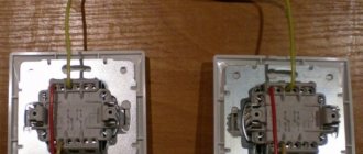
Installation example of a 2-gang switch with backlight
The main design differences between LED switches are in the backlight mechanism. It can be ready to use and does not require any action to connect it. Another type of design requires connecting wires that power an LED or neon lamp.
Let's consider a more complex option - how to connect a backlit device, in which the conductors need to be connected independently.
A design feature that allows easy access to the backlight wires can be useful if you need to turn it off
First of all, pry up the keys with a screwdriver or other suitable tool and remove them. Separate the core (internal mechanism) from the body.
Next, determine the correct position of the switch using an indicator. To do this, by touching the contacts with a screwdriver on one side and an indicator on the other, check whether the device is on or off.
If the indicator lights up, it means it is turned on. In this state, turn it so that the keys with the pressed side are located on top.
For a regular indicator screwdriver to work, you need to hold it correctly - the metal part must touch the contact plate, and the top must be touched with your thumb
One of the wires coming from the indicator is connected to the input terminal, and the second is connected to the key contact. If there are several keys, then the wire is connected to the first of them, starting from the left. Simultaneously with the wire going from the indicator to the input terminal, the phase conductor is also connected.
The two outlet phase wires that go to the chandelier are connected to the output terminals simultaneously with the second backlight wire, making sure that it does not fall out of contact.
With this connection method, the backlight will turn on after opening the contacts using the first key. The second will not have any effect on turning off the backlight, and the light will remain on even when the lighting is on.
In order for the indicator light to go out when you press any of the keys, you need to make a jumper yourself that will connect the indicator to both keys.
If you do not take into account the connection of the backlight, installation proceeds as in a conventional device. A phase conductor is led through the junction box to the switch and connected to the input terminal L, inserting it into the hole and screwing it in with a screw.
Next, two outlet phase wires are connected to the device contacts L1 and L2, which also lead to the chandelier through the junction box. One of them is connected to one lamp, the other to the other two. The zero passes through the junction box in the wiring box, then goes to all the chandelier lamps, closing the contact.
As a result of correct connection, the first key will turn on one lamp, the second two, and two turned on keys will lead to the activation of the entire lighting device. When switched off, the LED (+) should light up.
How the device works
First you need to understand how the dimmer works. The principle of operation is to smoothly regulate the voltage that is supplied to a controlled light source, for example, a spotlight.
Photo of a Siemens dimmer
Simply put, the device can change the voltage that goes to the light bulb from 0 to 100%. The lower the output voltage, the dimmer the glow will be. At the same time, there are different types of dimmers that differ not only in appearance, but also, of course, in their operating principle, namely:
- control: wheel (rotary), button (push), sensor (electronic);
- application: halogen, fluorescent, LED light sources or incandescent lamps;
- additional features: timer, remote control, clap on, smooth shutdown, etc.;
- design: modular (mounted on a DIN rail), monoblock (mounted in the wall, like sockets).
So, now let's look at the basic requirements for installing and connecting a dimmer with your own hands.
How a backlit switch works and works
We will describe the design of an LED switch using the example of a two-key backlit device.
The mechanism consists of the following elements:
- one input, two output terminals;
- current limiting resistor;
- moving contacts.
The design also includes a housing, a decorative panel and key pads.
When the contacts of the LED switch open, the current flowing through the phase wire flows to the resistor, then to the LED or neon lamp. Next, the voltage passes through the lighting fixture and exits through zero.
Since the backlight is connected through a current-limiting resistor, the voltage in the network decreases and is enough for illumination, but not enough for the chandelier to operate.
After the switch contacts close, the current, which always moves along the circuit with the least resistance, passes through the network that powers the lighting lamp - in this circuit the voltage is practically zero. The current also flows to the backlight circuit, but it is so small that it is not enough even to operate a neon lamp.
Disabling the indication circuit
If necessary, the backlight elements can be removed. Such a need may arise, for example, when LED or energy-saving lamps flicker unpleasantly, caused by the flow of a small current through the limiting element. This problem can be solved in other ways, but it may happen that removing the indication is the only solution. In this case, you will need small wire cutters.
The work of removing the indication chain can be carried out on a dismantled device, or you can not dismantle the switch with the LED, just remove the decorative plastic parts. In any case, before starting work, you must turn off the power to the lighting network using the switching device in the switchboard. After this, make sure there is no voltage directly at the switch.
After gaining access to the internal structure of the device, it is enough to cut off any LED pin. This will open the indication circuit. But it is better to completely remove the LED or neon to avoid accidental short circuits with cut leads.
Two-key device with a neon light bulb.
Removing the plastic parts may not be enough to gain access to the backlight chain. In this option, you will need to continue disassembling the device. In most cases, this cannot be done without removing the switch from its installation site.
In the video they remove the LED from the switch very quickly.
How to connect with your own hands: rules and diagrams
Below are diagrams for connecting switches of various types, including how to connect two-key (double) mechanisms with your own hands.
Attention When connecting an illuminated switch, you must adhere to the same rules and safety measures as when working with conventional devices. First of all, you need to de-energize the room. Next, you can begin dismantling the old switch:
Next, you can begin dismantling the old switch:
- remove the cover using a flat-head screwdriver;
- pull out the device by unscrewing the screws that held it in the installation box;
- disconnect the wires.
The internal mechanism can be disassembled into parts and used for domestic purposes. Before installing a new device, you must make sure that the type of lighting in the switch is compatible with the lamp in the luminaire. It should be taken into account that connecting to a fluorescent lamp will subsequently cause it to blink in the dark. It is possible to avoid such a glow only by installing a resistor with a resistance identical to the backlight in parallel with the lamp.
Single design
Let's look at how to make a backlight on a single switch with your own hands. To install a single switch with an indicator, you need to insert the internal mechanism into the socket box. Connect the wires to the contacts of the device and secure the structure with bolts. Lastly, the frame is installed and the key is inserted directly. The final stage will be to check the operation of the structure. When assembled correctly, the backlight in the switch glows when off.
Two-key mechanism
Switches are quite common, the design of which implies the presence of several keys. This allows you to control the operation of several lighting fixtures or devices located in different rooms at once. How to install this type of switch? Installation of this type of switches is similar to single ones. The difference is the presence of several wires from consumers. An important point will be the correct order of their connection.
Important To install the structure, you must use an indicator to determine the phase of the current. The switch is connected as follows:. The switch is connected as follows:
The switch is connected as follows:
- after dismantling the old device, three wiring remains, one of which is responsible for the incoming power, and the other two for power from the light source;
- turn on the mains voltage and use the indicator to install the wire with the phase;
- then disconnect the network from the power source, remove the insulation from the wires;
- determine which switch position corresponds to a switched-off light source;
- Unscrew the screws at the three contact groups of the switch, attach them to the plate and screw them back;
- using a screw, screw the phase wire to the plate, and the wire going to the lamp must be connected to the contact;
- Connect the remaining wire to a contact without plates;
- secure the connected mechanism in the socket box and install the keys;
- turn on the current source and check the correctness of the assembled structure.
other material
Passing mechanism
The essence of the work of a pass-through switch is the ability to turn on the light in one room and turn it off in another. This is due to the installation of a moving contact. When you press the switch key, it moves to another contact and turns on another circuit. To connect a pass-through switch, you need to install two devices on both sides of the circuit and connect them to each other with a three-core cable. When you press the key of the first switch, the circuit is closed and the lamp turns on, when you press the key of the other, it turns off.
Application requirements
The most important requirement when choosing a dimmer is to determine in advance which lamp it will be connected to. Products for halogen lamps cannot be connected to LEDs.
Also important criteria are:
- minimum light source power;
- room temperature – it is not recommended to set the dimmer in the room above 25 degrees;
- the phase conductor must be broken; it is prohibited to connect the neutral;
- the dimmer power must be higher than the total load of all lamps to which it is connected;
- You cannot connect capacitive and inductive loads to the regulator at the same time.
Failure to comply with these requirements may lead to negative consequences.
Connecting a two-key switch: diagrams, tips, instructions
- Design and principle of operation of a two-key switch
- Preparatory work
- Connecting a two-gang switch
- Connecting a two-key switch with backlight
- Useful tips
A two-key switch is a very important element for adjusting the level of lighting in an apartment or private house. The light bulbs can be arranged in groups or one at a time, and the light can be supplied to them by a separate key.
Very often during repairs when carrying out new wiring, the question arises of how to connect a two-key switch to provide several lighting modes. How to connect a two-key switch taking into account the necessary safety measures - read on!
Design and principle of operation of a two-key switch
The design of the two-key switch is quite simple. It consists of:
- Two keys (moving parts up and down).
- Housing (shell), which is removed before starting work with electricity.
- Terminal blocks (those places to which voltage or current is supplied).
Rarely, the third element - terminal blocks - can be replaced in the design with screw terminals. The difference is that the former hold the wire for a long time and securely, and the latter do the same, but not by pinching the wire, but by twisting it, so the first option is easier to connect and lasts longer. The design may also include additional lighting - a dimmer located on each key. Read below about connecting a two-key switch with dimmers.
Inside the two-key switch without backlight there are two wires running parallel to each other and an input for the phase. Each of the terminals suitable for the keys can, independently of the other, open or close the contact, as a result of which one lamp (part of the lamps), the second lamp, or all the lamps together turn on
.
Note! If you need to supply current not to one, but to several light bulbs at once. It is imperative to use stranded wires. This is exactly what the two-key switch model allows you to do.
The principle of operation of the switch is to vary the degree of illumination:
- You can turn on only one key so that one light bulb (or the first group of lights) lights up.
- It is possible to turn on the second key - the lighting will change, since some parts of the room will be clearly visible, while others will be slightly darkened.
- The third option is to turn on “to the fullest” - both keys are in the “on” position - then the room receives maximum illumination.
By the way, some two-key switches consist of two single-key devices isolated from each other. In this case, it is customary to call them modular.
In addition to the external component, such a device can also perform the functions of saving energy and creating a varied atmosphere. Two-button switches also increase safety, since when they are installed in a room, the number of points with electrical voltage is reduced.
Before starting work on preparing to connect the switch, we suggest that you familiarize yourself with the diagram of the two-key switch below:
Resistor resistance and power
The above resistor parameters correspond to a 220 V network voltage. It happens that the LED lamp is powered from a line of a different rating. Then you will have to calculate the resistance and power of the resistor yourself.
We calculate the resistance using the formula R=∆U/I, in which ∆U is the difference between the actual voltage in the device’s power supply line and the lamp voltage, I is the LED current.
The light bulb will work normally if the resistor value is in the range of 150 - 510 kOhm.
We calculate power using the formula P=∆U×I, where the letter values are similar to the above explanations.
Knowing these formulas, it is easy to make the necessary calculations of the resistor value.