Home » Automation and controls » Why and how automation is needed on old-style gas boilers
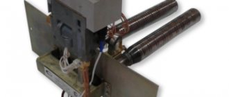
The newest models of gas boilers are characterized by high power and heating speed. However, their prices are steep, to put it mildly. You can try to use a more economical option and install new automation on the old boiler or fix the old one. The operating principle and automatic design of old-style gas heating boilers will be explained in this article.
…
- 1 Why do you need gas automation?
- 2 The principle of operation of automation on old-style gas boilers
- 3 Basic elements of automation
- 4 Flame and draft sensors
- 5 The most common automation malfunctions and methods for eliminating them
Why do you need gas automation?
Old-style boilers were manufactured in accordance with the gas parameters and heating system features that were in use several decades ago. These are, for example, models KChM, AOGV. At the same time, their durability allows them to be used for many years to come. But the problem with automation is that quite often it breaks down. In such a situation, there are three options:
- diagnose existing automation and replace the necessary parts;
- equip a reliable and high-quality unit with a modern automatic system;
- buy a new boiler.
The difference, of course, is in the price of the issue, the effort and time of the owner.
Let's consider the cheapest option - troubleshooting gas automation on an old boiler. However, first, let’s figure out why an automatic system is provided in the coolant in general.
Gas automation allows you to regulate and maintain the required level of coolant temperature, and also serves to automatically stop the gas supply in an emergency situation. Installing automation on an old gas boiler will allow you to be sure that if the burner flame goes out, then after a short time the system will work to stop the gas supply without your participation.
Attention! Automation, in addition to regulating and maintaining the temperature at a given level, ensures the safety of using the heating device and allows you to save on heat consumption.
If you want to change the automation, keep in mind that domestic manufacturers produce models that are suitable for almost any old coolant. Imported automation cannot be installed on everything. In addition, when installing foreign automation on old-style gas boilers, not all of its functions may work - the design features of the boiler will not allow it.
…
On a note! The choice of automation for gas boilers is varied. The most popular is the system from Italian manufacturers, for example, SIT. American automation (Honeywell) holds second place in popularity. There is a large selection of Russian (SABK, "Orion") and Ukrainian, "Iskra", "Plamya", APOK-1).
Types of valves
The gas valve is responsible for regulating the gas flow, its distribution and shutting off. The valve has a hole for the passage of gas (the so-called seat), closed by a piston or disk.
Depending on the number of inputs and operating positions, there are one-way, two-way and three-way valves, as well as modulating ones:
- a one-way valve is either open or closed;
- two-way is equipped with one input and two outputs. The start is smoother due to opening through an intermediate position;
- three-way valves are installed on boilers with two-stage power;
- With the help of modulating valves the power can be adjusted smoothly.
Accordingly, gas burners (types of gas burners for heating boilers) with automation for heating boilers come with single-stage, two-stage or modulated power control.
The principle of operation of automation on old-style gas boilers
Frequent problems when heating a room with gas boilers are flame attenuation in the burner and gas pollution in the room. This happens for several reasons:
- insufficient draft in the chimney;
- too high or too low pressure in the pipeline through which gas is supplied;
- the flame on the igniter goes out;
- leakage of the pulse system.
When these situations arise, the automation is triggered to stop the gas supply and prevent the room from becoming gas-filled. Therefore, installing high-quality automation on an old gas boiler is basic safety rules when using it to heat a room and heat water.
All automation of any brand and any manufacturer has one operating principle and basic elements. Only their designs will differ. Old automatic machines “Plamya”, “Arbat”, SABC, AGUK and others work according to the following principle. When the coolant cools below the temperature set by the user, the gas supply sensor is activated. The burner starts heating the water. After the sensor reaches the user-specified temperature, the gas sensor automatically turns off.
On a note! When using modern automation, it is possible to save heat up to 30%. Old-style automation is non-volatile and does not require electricity. Its adjustment, connection and disconnection are carried out by a person. Commands are transmitted using electromagnetic pulses.
The video explains how the automation of gas boilers AOGV and KSTG works.
…
Malfunctions of AOGV with a Honeywell or Eurosit unit
So! You have a gas boiler AOGV Zhukovsky, or maybe Borinsky with a Honeywell or Eurosit 630 gas valve. Below we will describe the most incomprehensible malfunction in the entire history of our work. Moreover, we are not 100% sure until the end. The details of what was happening were understood almost completely and this issue had been resolved more than once with a positive result. But, nevertheless, some uncertainty is still present. Maybe this will go away over time, after completely disassembling the valve, when possible. OK then. Steam boilers DKVR stands for double-drum, vertical-water-tube reconstructed unit.
Main symptoms. It starts as if from afar. There are no signs of trouble. For no apparent reason, the working boiler suddenly turns off. The boiler may be working properly for several months before this starts. Or maybe even several years. Well, it turned off, and it turned off. We approach the boiler. Let's launch. Works. After this strange failure, a day or even a week usually passes . And the situation repeats itself. The boiler may turn off, for example, at night. After this, boiler shutdowns become more frequent, and as a result, the boiler cannot be started at all. We release the button and the igniter goes out.
Something that usually immediately confuses specialists . (But the malfunction is the same.)
1. Everything is fine. Idle speed works. (The igniter is lit.) You set the desired temperature. The boiler reaches this temperature and suddenly turns off along with the igniter. Then, the boiler cannot be started at all until it cools down. After a couple of hours, the boiler can be turned on, but the situation immediately repeats itself. Or something else.
2. Start the boiler. It works. It's gaining temperature. Cotton. Gas release from igniter. Everything goes out. And then, until the boiler has cooled down completely, you don’t even have to come close. The gas worker, for example, cleaned the pilot burner. It worked for a day and again the same story.
Next, look at the top picture. What do you usually do right away? They pull the wires off Thermocouple Breaker No. 3, wind a wire jumper and try to start the boiler. After the boiler does not start, and it usually does not start in 90% of cases, almost everyone begins to blame the gas valve, claiming that it is faulty, or the solenoid valve located inside the gas valve. Replacing the gas valve with a new one does not solve the problem. Or, as mentioned above, a day passes, or, at best, a week. And then a complete repeat of the situation. This, of course, got old very quickly, but let’s not blame anyone who could help us, right? Therefore, let's get down to business.
Entering information 04/17/2013 To quickly diagnose such a malfunction, see the article Malfunctions of automatic control for traction and overheating of AOGV with imported units. Here is a specific list of actions that will help revive the boiler or repair it.
1. First we will get used to the big picture. Let's approach the boiler and use our eyes to find everything we need here by looking at the elements. There is no way without this.
2. Then we will analyze the work of each element in this chain separately. This will greatly help to see the overall picture of the boiler's operation.
3. Let's make a diagnosis and figure out the situation together. I advise you to take your time and study everything carefully, because the matter here is so delicate that if you don’t have basic attentiveness, you won’t be able to do anything. Run to change the boiler for a new one, as some people usually advise, having been stuck with the boiler until late at night, or just quietly let the oak go to minus -30C, buying up all the thermocouples, valves, and giving away about ten of them for nothing.
1. This is a Honeywell gas valve . There may be another valve. By the way, it must be said that this malfunction directly affects AOGV boilers with a capacity of 11.6, 17.4 and 23.2 . These boilers are equipped with simple valves. There are more complex valves, such as the 820 Nova or Honeywell, which use two thermocouples: one for the gas control, the other, multiple, for the thermogenerator. These units are installed on AOGV 29.1 and more powerful boilers. We are not talking about them now.
2. This is a thermocouple . It is heated by an igniter and generates EMF. This EMF keeps the valve open. The thermocouple will cool down and the valve will close. Thermocouples for Honeywell units - list. If you need to know more about the work, click here.
3. This is a thermocouple breaker . It is also called a thermal breaker. The great setback is that the breakers are only supplied for Eurosit units. They have M9 thread. And the Honeywell unit has a thread for an M10 breaker.
4. Thermal relay 90C . Or 95C. 90C is the temperature at which the relay is activated. Boiler boiler protection.
5. Button KM1-1 . Or a small-sized button KM1-1. Doesn't matter. Essentially a regular electrical push-button switch.
6. Thermal plate. Here it is a little different. Not the same as installed on your boiler. Your thermal plate has a nut welded in and an adjusting screw. If there is poor draft in the chimney, the plate bends and presses the KM1-1 button. The boiler turns off.
When we looked, found all the elements and even felt them with our hands, we move on to analyzing the work of each element separately.
Currently not supplied by the factory. More precisely, it is installed as it was, only under a different name - Mertik Maxitroll . This is not an analogue, this is what it is. Remove the cover from yours and you will see this name. To start the boiler, we turn the handle to the Spark position and push it down. The gas went to the igniter. After that, we turn the handle, click the piezoelectric element (in this block it is built into the valve and controlled by the handle), the igniter lights up and wait 30-45 seconds for the thermocouple to warm up. After this, release the handle. The solenoid valve remains in the open position, powered by EMF from the thermocouple. Turn the second knob of the temperature regulator, opening the gas to the main burner. The burner is lit by a working igniter.
2. Thermocouple. The thermocouple is placed at one end into the igniter flame and, when warmed up for 30-45 seconds, begins to generate an EMF of 20 mV. These 20 mV keep the block solenoid valve in the open position .
Honeywell units have several types of thermocouples. In essence, they are no different, only they are curved differently, attached to the igniter differently and have different lengths. We give, for example, a photo of a thermocouple for AOGV 17.4 and 23.2 boilers with a Honeywell unit manufactured since May 2004.
3. Thermocouple breaker. Or Thermal Breaker . The breaker consists of two parts: sleeve + insert. The sleeve is screwed into the gas valve at one end. A thermocouple is wrapped into the other end of the sleeve. The insert is arranged as follows. See photo.
The thermocouple is wrapped and pressed against this small area located in the middle of the dielectric. It transmits its 20 mV to one of the contacts. Wires are connected to both contacts of the breaker. 20 mV comes from the heated thermocouple to the pad, through the lower contact along the wire goes into the circuit, which can open at any time depending on which of the overheating sensors is triggered. And, if all sensors are closed, it calmly goes to the upper contact, and therefore to the contact of the solenoid valve built into the block. More details below.
4. Thermal relay 90C or 95C. This is a regular thermostat. We call it a tablet.
Thermal relays are installed on almost all gas equipment. The tablets have different operating temperatures from + 77 C to +110 C. Thermal relays are installed in case of overheating. In our case, the tablet is responsible for overheating the boiler. ATTENTION! The thermal relay is always normally closed . When the response temperature is reached, it opens and breaks the electrical circuit through which our 20 mV is supplied to the solenoid valve. Practice shows that the thermostat does not last forever. After two or three operations, it may no longer return to its original normally closed state.
5. KM1-1 button and Thermal plate. A very strange device.
The KM button is an ordinary switch. The button, when pressed, opens the outer contacts. The wires of our electrical circuit are connected to these extreme contacts. The thermoplate acts as a button press in case of overheating, such as poor traction. Here, in the photo, the thermal plate is different, from the Economy block. We haven't received another one yet. The original thermal plate has a nut welded into it, into which the pressure adjustment screw is screwed. In general, the meaning is this: if overheating occurs in the chimney area, the thermal plate bends and presses the KM1-1 button, breaking the circuit.
Now we connect all the elements together and figure out what’s wrong with the operation of the boiler.
Let's first imagine how our entire circuit works. The thermocouple produces 20 mV. These millivolts from the lower contact of the Breaker make a circle along the blue arrows, passing through the thermal relay sensors and the KM button, and arrive at the upper contact. Millivolts are removed from it to the solenoid valve. This is all.
How we dealt with the situation . When, by the way, it comes to repairing a boiler, time can pass for hours. So. We arrive at the house. We have an AOGV-11.6 with a Honeywell unit. A new unit was purchased from us a day ago and installed on the boiler . The client repeats the words of the specialist who performed the work: “ Your new gas valve is faulty . By the way, this phrase is usually heard without objective evidence.
A slight departure from the topic. There is one small oddity here. This is what I mean. A person is usually always normal. But for some reason this normality disappears after he becomes a client. Something is happening to him. Something suspicious. How to put it mildly. When he listens to what the experts say to him on a call. He... is getting dumb or something... well, in general something like that. Moreover, he always gives money to a specialist. At least four times. Why bring yourself to this? Control the situation! This is your boiler, your home and your warmth!
So. We repair a boiler with a faulty gas valve. )))))
Let's return to the topic. How was it? Based on real events.
1. We have an electrical circuit. Its starting point is Thermocouple and its destination is Solenoid Valve . Checking the chain.
We unscrew the thermocouple from the Interrupter sleeve. Press the solenoid valve button. Let the gas flow to the igniter. Ignition. Warm up the thermocouple for 30-45 seconds. What will a specialist do without a tester? Nothing. We measure the EMF tester. (More details here or here). The output is clearly 20 mV. Great!
All. They forgot about the thermocouple. She is alright.
2. Look at the last picture. Do you see the blue arrow going to the right from the bottom contact of the Breaker? Screw the thermocouple back. We pull the wires from the contacts of the breaker. We light the igniter. Now one tester probe is on the body, the other is on the lower contact of the breaker. ATTENTION. The probe contacts must be tight . Give it a good squeeze! Otherwise, we will not find 20 mV there. They pressed me. We looked. There is tension!
3. Then suddenly I notice a thin wire that bridges the lower and upper contacts of the breaker. Yeah. Is the jumper installed? Costs! Is the thermocouple warm? Yes. Does it output 20 mV? Yes. I release the button. The igniter goes out. After 15 repetitions of igniting and releasing the button, I am exhausted. The valve doesn't hold and that's it. I mean, what? Is the new unit really faulty? The thermocouple is working. The jumper is in place. What else is needed
4. Break 15 min. I think I'll be leaving. Reflections during the break. How interesting it is that some lousy 20 mV keeps such a button pressed (open), which is difficult to hold with your hand for a minute . And I laugh. You've just been pressing it for an hour and a half. The hand is gone.)))
5. I’ll probably go slowly. I understand. The man came and really wanted to fix the boiler quickly. I pulled the wires off the Breaker. I wound a jumper between its contacts. Right. I immediately eliminated the entire chain. I connected millivolts directly from the lower contact of the Breaker to the upper one.
Then something strange happens. Something took me and pulled me to set the tester to ring and use the probes to grab both wires that go to the sensors from the Interrupter. When I heard the tester call, I couldn’t believe my ears! I applied it again and again. The chain is ringing! That is, she is working properly! What nonsense is this? The boiler must be working.
6. Okay. I remove the screwed jumper. I put the contacts back on the Breaker. Launch. Warming up the thermocouple. I release the button. The igniter goes out. Again. Again. A slight hysteria begins.
7. These are the thoughts. And the button is really hard to hold down. Only 20 mV. Then I remember this. In a car, by the way, only 12 V are moved and the whole engine is turned and it starts. There was once a case when, with a working battery, I turned the key, but the starter did not turn. What was the matter? IN THE DENSITY OF CONTACT. Tightened the nuts more. Increased the contact area. The larger the area, the greater the EMF.
8. I remove the contacts from the Breaker. I wind back the previously wound wire. Launch. Warming up the thermocouple. And with a tester on the thermocouple body, one probe, the other on the lower contact. There is 20 mV. AND NOW THROUGH THE JUMPER TO THE UPPER! OPA! And there I have ZERO. No tension! The probe is tighter to the contact. No. Eat! Some jerks and again ZERO. What about the jumper? And it has a small contact area!
9. I ask the owners to find some copper wire. Found. I clean it with a file and flatten it with a hammer. And I reel in more. Ignition. Warming up the thermocouple. I release the button. AND SHE HOLD ON. I move the button from the Spark position to the Heating position. I move the temperature control knob. The main burner lights up!
10. While heat begins to flow into the house, I look at the disconnected wires going to the sensors. Rave! The chain remains the same. The cross-section of the wire remained the same. What's the matter? The chain is fine. She's calling. All sensors are working. Well, several months have passed since the boiler started working? OK then. No one is freezing anymore and the boiler is working.
It was interesting when this boiler suddenly switched off again after three days with the jumper well installed at that time. We spent another half a day trying to figure it out completely. And still it was not a valve! The whole issue turned out to be the internal contacts of the breaker . Between the top contact and the insert . There, such a rod removes millivolts and sends them to the solenoid valve. Why he stops doing this over time is still a mystery.
So, if you have a case when, even with a cool jumper placed on the Breaker, nothing is going to work, keep in mind THESE ARE THE CONTACTS INSIDE THE BREAKER. This is not a valve! The breaker should simply be replaced or the thermocouple screwed in, turning the breaker directly into the block. This does not happen with Eurosit thermocouples. There is a reserve in length. But with thermocouples for Honeywell blocks it’s worse. One end of it, as a rule, is fixed to the igniter, and the other end simply does not reach the block.
Otherwise, everything is not so disgusting. Carefully ring the entire circuit and all sensors. Maybe the tablet has opened, maybe there’s something wrong with the KM button. But what could be wrong with the button?! In general, CONTACTS, CONTACTS AND AGAIN CHECKING THE CONTACTS.
Now the main thing! We don't have thermal breakers for Honeywell units yet! What is shown in the photo is a breaker from the Eurosit unit. But the insides are the same. They can be easily used.
The complete set for treating the situation is as follows: breaker + KM button + tablet. And, of course, we are not against replacing the valve with a new one)))). But, I would like to become smarter over time, and not vice versa.
Good luck to all! And advice. If you have gas appliances on which heating, water supply or hot water depends, give yourself a tester for the New Year. Save a lot of money. Even the most reliable and branded boilers are good as long as they are new. And then it may turn out that no one will be around. This is where the tester comes in handy. Thanks to all!
Source: https://www.tskl.ru/shop/assident_kkk/kollection_stop/accident_honeywell/page_1/
Basic elements of automation
The main elements of automation for a gas boiler are:
- thermostat;
- shut-off valve;
- traction sensor;
- flame sensor;
- igniter tube;
- igniter;
- burners.
Let's try to clearly explain how automation for a gas boiler works, breaking it down into its main elements and talking about their functions.
The gas passes through a gas purification filter. Next it goes to the solenoid valve, which regulates the fuel supply to the burner. Temperature and draft sensors are located next to the valve, monitoring the indicators and signaling if they exceed acceptable standards. Also, the automation kit for gas boilers includes a thermostat with a bellows and a rod, designed to set the desired temperature. A special button is used to adjust the indicators. When the water is heated to the temperature set by the user, the thermostat is activated, the gas supply to the burner is stopped, while the igniter continues to operate. When the water cools by 10-15 degrees, the gas supply is resumed. The burner lights up from the igniter. The automation is started manually.
Automatic control of boilers, burners, boiler units, heat generators, furnaces
Convenient automation keeps the functioning of electric and gas heating boiler systems under strict control. Carries out correct control of boiler generators, burners, furnaces and heat generators. Reduces automation costs, increases maintainability and overall reliability of work equipment.
Main characteristics of our burner controls
| Characteristic | Model | |
| PRAGO, burner control | SAFAR, automatic burner | |
| Operating voltage | ~ 220V/50Hz or =24V | — 220V/50 Hz or =24V |
| Power consumption, no more | 15 VA | 15 VA |
| Maximum terminal load | 1.5A | 1.5A |
| Fan motor | 2A | 2A |
| Solenoid valves | 1A | 1A |
| Air damper servomotor | 1A | 1A |
| Fault indication | 1A | 1A |
| Degree of protection | IP40 | IP40 |
| Permissible temperature, 0C | from - 40 to +70 | from -40 to +70 |
| Characteristic | Model | ||
| SAFAR-400, cabinet | SAFAR-BZK-WATER, cabinet | SAFAR-BZK-PAR, cabinet | |
| Operating voltage | 24 | 380V (+10..-15%) / 50Hz | 380V (+10..-15%) / 50Hz |
| Power consumption, no more | 5kVA | 7.6kVA | 7.6kVA |
| Screened sensor cable length | 20M | 20M | 20M |
| Degree of protection | IP20 | IP54 | IP54 |
| Ambient temperature | from -20 to +50°С | from -0 to +70°С | from -0 to +70°С |
| Device dimensions, mm | 145 x 195 x 61 | 500x400x270 | 500x400x270 |
| Type of connected temperature sensor | — | Pt100 | Pt100 |
| Characteristic | Model | ||
| SAFAR-AMK-ShchD | SAFAR-400-WATER, cabinet | SAFAR-400-PAR, cabinet | |
| Supply voltage, V | 220V/50Hz | 220 (+10 …– 15%) 50 Hz | 220 (+10 …– 15%) 50 Hz |
| Energy consumption | 50VA (ignition 300) | 7.6A | 7.6A |
| Switching rated voltage of relay outputs | ~220V/50Hz | ~220V | ~220V |
| Switching current of relay outputs | 2A | 2A | 2A |
| Fan motor voltage | ~380V/50Hz | 380V (+10 …– 15%) 50 Hz | 380V (+10 …– 15%) 50 Hz |
| Switching current per fan motor | 2A | 3.5A | 3.5A |
| Switched current to the smoke exhauster motor, A | — | 7 | 7 |
| Discrete input signals, V | ~220V | 24V | 24V |
| Shielded cable length | 20m | 20m | 20m |
| Protection class | IP54/IP20 | IP54 | IP54 |
| Device dimensions: height x width x depth, mm | 114x60x75 57x144x90 | 500x400x270 | 500x400x270 |
| Ambient temperature | 0÷70 Cº | 0÷70 Cº | 0÷70 Cº |
| Weight, no more | 1.5 kg | 12 kg | 12 kg |
| Analog input signals | — | 4 to 20 mA | 4 to 20 mA |
You can find a complete list of items and prices in our price list
Flame and draft sensors
Flame and draft sensors work on this principle. The draft sensor reacts to deteriorating smoke draft and transmits an impulse to the control system. It is located in the smoke hood. Equipped with a plate made of an alloy of two metals: iron and nickel. When draft deteriorates, flue gases accumulate and heat the plate. It becomes deformed, the contacts open, and the flow of fuel into the combustion chamber stops. When the temperature decreases, the plate returns to its normal state.
The temperature sensor works on the same principle. When the water in the boiler heats above the set temperature, the lever mechanism is activated and the temperature regulator valve closes. The gas supply stops and the burners go out.
When the water cools, the sensor bellows contracts, the lever mechanism is activated, the temperature regulator valve opens, gas begins to flow, and the burners light up.
Gas equipment for KChM 630 EUROSIT
In distant post-Soviet times, when natural gas for the population cost nothing, solid fuel boilers began to be produced with gas fittings of the APOK-1 type, which replaced solid fuel in the form of coal and wood. The gas supplied to the KChM had a complex and cumbersome device with burners that consumed gas within large limits. Nowadays, they have begun to produce more modern and economical gas boilers that consume less gas, but not all owners of private houses can afford them. Of course, old KChM boilers are not so aesthetically pleasing and modern, but if they are modernized, they can serve as heating devices for many years.
By material and type of heat exchanger
Heat exchangers can be:
- cast iron;
- copper;
- aluminum-silicon;
- made of carbon or stainless steel.
The design of the heat exchanger may also vary.
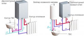
The most popular are separate heat exchangers. Heating water flows separately, and water for residents’ household needs passes separately. They are a little more expensive, but more reliable.
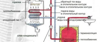
A bithermic heat exchanger looks like a pipe within a pipe. In the inner pipe there is DHW water, which needs to be heated, and in the outer pipe the heating coolant circulates.
The third type is a heat exchanger in which a coil is built in. The container with water is heated by the coolant flowing in the coil. An indirect heating system is good for everyone, but in the summer you will either have to heat the boiler or live without hot water.
The bithermic option is not recommended for use where there is hard water. And be prepared that every time scalding water will flow out of the tap first, and only then at the temperature you need.
Connecting the thermostat
When connecting a conventional thermostat to the boiler (as an element of automation), operating comfort increases and gas consumption is reduced. This occurs due to the fact that the boiler is controlled by a sensor installed in the thermostat itself and turns off the burner when the set air temperature is reached in the room.
Taking into account the fact that the volume of air in the room is several times (or even tens of times) greater than the volume of the coolant, its cooling rate is several times lower than the rate of temperature drop in the boiler.
However, in this operating mode it is impossible to adjust the coolant temperature using the thermostat itself. Therefore, the value on the boiler is most often set to the calculated maximum. This is done to ensure that the boiler reaches the set temperature as quickly as possible. However, this method has one negative side. The media temperature either rises to maximum or drops almost to room temperature during idle time. During the off-season, this can lead to uncomfortable sensations. The radiator is either cold or hot - this is not very convenient.
Checking the serviceability and replacing the automation
The periodicity of checking the automation systems of boilers operating on gas fuel is stipulated in SNiP. Maintenance is carried out twice a year during a scheduled inspection, before and after the end of the heating season.
The following signs indicate the need for repair work:
- Increasing frequency of automatic malfunctions of gas-fired boilers. A problem is considered to be a situation in which the boiler turns off on its own every few weeks.
- Spontaneous extinguishing of fire.
- Ignition system failure.
Maintenance and adjustment of the automatic gas heating boiler, in accordance with current rules, is carried out exclusively by qualified personnel who have the appropriate permit and license. Electronic control unit requires installation of special software (firmware).
During the next seasonal inspection, the microprocessor is diagnosed, which is required by the rules for servicing relay automation. Most controllers have a problem diagnostic function installed, a report of which is stored in the device memory. Error information is taken into account when configuring the module.
A complete replacement of the automation is extremely rarely required. In most cases, individual components are changed: thermocouple, valves, sensors, etc.
Design features and advantages
Modifications of the Aton gas boiler are based on the basic version - a boiler with a sectional heat exchanger and an atmospheric burner for gravity-type heating systems with the ability to connect a circulation pump. The boiler design is determined by:
- type of automation;
- rated power;
- executable options.
Heating boiler Aton
Combustion chamber control ensures uninterrupted operation of the burners at a given power level or when switched off. The combustion chamber fittings are equipped with line pressure and combustion pressure connections. The storage product for processed products is connected to a deflector and a smoke exhaust valve.
The heat exchanger insulation is reinforced mineral wool. The generator casing is covered with a wear-resistant coating.
The Aton heating generator is included in the high utility class, in addition, with the following qualities:
- do not require connection to an external power source;
- high-tech burners;
- surfaces are coated with an anti-corrosion compound;
- single-circuit and double-circuit devices;
- original design;
- ease of maintenance;
- efficiency;
- compactness;
- strength;
- accident-free;
- modern design.
