MEGAOMMETER on Atmega328R
The industrial version of the megohmmeter is quite large and has considerable weight. The only advantage of this monster is that it is verified, but if you urgently need to measure the leakage resistance during repairs, then the electronic version is more preferable.
Having searched on the Internet, I did not find a simple device; the only megohmmeter that was repeated by radio amateurs was from the Silicon Chip magazine, October 2009, but with modified firmware. The device we bring to your attention has dimensions of 100x60x25 (the housing was purchased on AliExpress) and weighs no more than 100 grams. The device is assembled on an Atmega328P microcontroller. Power is supplied from a lithium battery and the current consumption is about 5 mA. The lower the resistance of the circuit being measured, the greater the current consumption and reaches 700-800 mA, but it must be taken into account that circuits with a resistance of less than 10 kOhm are rare and the measurement is carried out in a few seconds. The device uses two DC-DC converters: MT3608 and MC34063. The first is used to power the controller, the battery voltage increases and stabilizes at 5 volts, the second converter is 100V, this is determined by the fact that it is mainly used for measuring leakage in electronic devices, and making a 500 or 1000V economical converter is very problematic. At first there was an idea to assemble both converters on the MT3608, but after I burned 8 microcircuits, it was decided to build them on the MC34063. And at 500, 1000V it was necessary to use a higher resistance divider and, as a consequence, the use of Rail-To-Rail operational amplifiers.
Indication is carried out on a liquid crystal display. To charge the battery, a TP4056 charge controller is used (separate 17x20 mm board).
The device is assembled on a double-sided printed circuit board made of foil fiberglass, manufactured using LUT technology. Don’t be afraid of the word “double-sided”. Two PP pictures are printed, bottom and top (mirror). They are aligned in the light and fastened with a stapler in the form of an envelope. The workpiece is inserted and first heated on both sides with an iron, then carefully ironed on both sides through two stands of writing paper. Throw the printed blank into a container with warm water for about half an hour, then remove the remaining paper with your finger under running warm water. After etching, we tin in Rose alloy. Through holes for conductors are made of tinned copper wire with a diameter of 0.7 mm. The inputs of the device are made of brass tubes from an old multimeter, so you can use standard probes from multimeters, but it is advisable to make homemade ones with alligator clips.
Used SMD parts, resistors 5%, capacitors 10%. It should be taken into account that this is not an ohmmeter and does not serve to accurately measure resistance, although the accuracy in the range of 1K - 1M is quite high. To increase the reliability of the readings, the entire resistance measurement range is divided into three. The firmware uses oversampling. Three voltage dividers are used: 1:10, 1:100 and 1:1000. The last range is very stretched, from 10 mOhm to 100 mOhm, and with a microcontroller ADC discreteness of 10 bits, it has a very large step, about 90 kOhm. In addition, we had to use protection circuits with the microcontroller input and they introduce an error in the two upper ranges. Below you see pictures with the measurement results.
Maybe someone will want to improve the device or calibrate it more accurately, so I am attaching the sources. When calibrating, we connect an accurate resistor no worse than 1%, for example 47 kOhm, and select a coefficient for the range of 10-100 kOhm in the line:
The scale from 10 to 100 mOhm is very non-linear, at first the readings are underestimated kx2, and at the end of the range kx1 are overestimated, so two coefficients are selected in the same way, but we set the resistor to 20 mOhm, then 47 mOhm and then 91 mOhm:
With best wishes, Samodelkin and Yu. Gradov.
Examination
Let's check the declared voltages and also measure the current consumption from the batteries in different modes. Voltage was measured with a Fluke 175 multimeter, current consumption with a Uni-T UT61E multimeter. Results:
Separately measured:
- Current consumption when output is off: 1.1 mA (identical for all voltage settings);
- Current consumption in the “OFF” switch position (completely turned off): 0.31 µA;
In my opinion, the results are excellent, the energy consumption is very acceptable and one set of batteries will last for about a day of continuous measurement in the most energy-consuming case.
Simple megohmmeter
To check the insulation resistance of an electric motor, cable or transformer, megohmmeters for the appropriate voltage are used.
Sometimes you need to roughly assess the insulation condition of a deep-well pump, welding transformer, electrical wiring, etc. This cannot be done with a regular multimeter, since its probes have a very low voltage, which cannot be used to check the insulation strength. To do this, you need an autonomous source of constant high voltage 1000V, and sometimes 2500V in production. A diagram of such a source is shown below. The device is a rectangular pulse generator with adjustable frequency and duty cycle, made on the NE555 chip. Adjustment allows you to adjust the operation of the step-up transformer to obtain the desired voltage at the output of the device. The step-up transformer is selected experimentally, made on a closed ferrite magnetic core, the turns ratio is approximately 1:50 - 1:100, the wire diameter is at least 0.08 mm on the secondary and at least 0.2 mm on the primary winding. When manufacturing a step-up transformer, care must be taken to ensure good insulation of the windings and terminals of the secondary winding. When placing parts on the high voltage side of the printed circuit board, sufficient distances must be maintained between the tracks and solder points. Otherwise, this may lead to a breakdown along the surface of the board. A neon light indicates the presence of high voltage. Any microammeter shunted with a shunt and calibrated according to standard resistances can be used as a pointer device. I used the recording level indicator from the Soviet Elektronika tape recorder. Power is supplied from two 9V Krona batteries connected in series. Everything is assembled in a plastic case and fits in your pocket.
If the pulse generator is assembled correctly, then the setup and calibration of the device is as follows:
1. Connect a dial multimeter to the high voltage terminals (a digital one is not suitable for these purposes due to the instability of the readings to HF pulses)
2. Connect a milliammeter (preferably a dial gauge) to the 18V power supply.
3. Completely bypass the microammeter
4. Turn on our megohmmeter
5. By moving the contacts of the trimming resistors, we achieve maximum output voltage from the high voltage side and minimum supply current. For example, 2500V at high voltage and a current of 30mA at a low supply voltage of 18V (for information: measuring electrical equipment with a voltage of 220V, 380V, an industrial megger should produce an output voltage of 1000V with a current of about 500μA)
6. Turn off the megohmmeter, disconnect all multimeters, close the high voltage output
7. Turn on the megohmmeter
8. Adjust the shunt resistance and mark “Zero” on the microammeter scale
9. Turn off the megger and connect the reference resistance 500 kOhm
10. Turn on the megohmmeter and mark the 500 kOhm division on the microammeter scale
11. We do the same with the reference resistance 1 MΩ, 10 MΩ, 100 MΩ starting from point 9.
This completes the setup. Subsequent calibrations may be necessary if the battery voltage drops over time.
About the details: the IRF540 transistor can be replaced with a less powerful one, diodes D1-D2 - any high-speed ones (at about 100 kHz), C3 - from 200 µF and above, D3 - a similar high-frequency high-voltage diode, La1 - any neon light bulb, T - an arbitrary boost small-sized ferrite transformer.
Attention! Working with the device involves high voltage that is dangerous to life. Therefore, compliance with and knowledge of the rules for working with megohmmeters is mandatory. After checking the insulation condition of electrical equipment, all live parts must be discharged by short-circuiting them between themselves and a grounded conductor for 5-10 seconds. High voltage capacitors should not be tested with this device as the resulting accumulated energy can be lethal.
External view of the device:
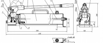
An example of manufacturing a step-up transformer:
Make a megohmmeter with your own hands
Good day, dear ones. A little preface. I needed a megaohmmeter for work. I was tired of carrying a domestic pointer monster with a handle around on trips, buying a good factory digital one is a toad, I tried a cheap Chinese attachment for a multimeter (Attachment for a DT266 current clamp) - I was disappointed in many ways. but above all, the flimsiness of the design, separate power supply using different types of power elements, and most importantly, the lack of stability of readings (when measuring the same cable pair, the readings differ slightly, but after studying RuNet, I only recently discovered the “Beaver-2” design on this site. although we are not talking about it now. that’s all. There is no other similar design even close. And only recently I managed to find two designs of one device in the foreign magazine SILICON CHIP . but unfortunately they wanted money. “kind sponsors” were found and helped find everything to assemble these devices.
Preface
A couple of years ago I became interested in choosing and comparing materials for soldering - solders and fluxes. I began to periodically watch specialized channels on YouTube where they conduct tests using the SIR (Surface Insulation Resistance) method. However, it was not possible to find test results for all materials of interest. I wanted to try to do them myself. For a long time, this was stopped by the fairly high cost of the device. But just now, having saved up a little at lunches, the required amount was collected.
Make a megohmmeter with your own hands
Free technical library:
▪ All articles A-Z ▪ Encyclopedia of radio electronics and electrical engineering ▪ News of science and technology ▪ Magazines, books, collections ▪ Archive of articles and search ▪ Diagrams, service manuals ▪ Electronic reference books ▪ Operating instructions ▪ Polls ▪ Your stories from life ▪ At leisure ▪ Random articles ▪ Reviews about the site
Directory:
▪ Great encyclopedia for children and adults ▪ Biographies of great scientists ▪ The most important scientific discoveries ▪ Children's scientific laboratory ▪ Job descriptions ▪ Home workshop ▪ Life of remarkable physicists ▪ Factory technologies at home ▪ Riddles, puzzles, trick questions ▪ Tools and mechanisms for agriculture ▪ The art of audio ▪ The art of video ▪ History of technology, technology, objects around us ▪ And then the inventor appeared (TRIZ) ▪ Lecture notes, cheat sheets ▪ Catchwords, phraseological units ▪ Personal transport: ground , water, air ▪ For those who like to travel - tips for tourists ▪ Modeling ▪ Regulatory documentation on labor protection ▪ Experiments in physics ▪ Experiments in chemistry ▪ Fundamentals of safe living (HAB) ▪ Fundamentals of first medical aid (FMA) ▪ Occupational safety ▪ Radio electronics and electrical engineering ▪ For a builder , home handyman ▪ Standard occupational safety instructions (TOI) ▪ Wonders of nature ▪ Spy stuff ▪ Electrician in the house ▪ Spectacular tricks and their solutions
Technical documentation:
▪ Diagrams and service manuals ▪ Books, magazines, collections ▪ Directories ▪ Parameters of radio components ▪ Firmware ▪ Operating instructions ▪ Encyclopedia of radio electronics and electrical engineering
Free archive of articles
(150,000 articles in the Archive)
Alphabetical index of articles in books and magazines Bonuses:
▪ Your stories ▪ Riddles for adults and children ▪ Did you know that. ▪ Visual illusions ▪ Fun puzzles ▪ Vivasan catalog ▪ Palindromes ▪ Solving a Rubik's cube ▪ Forums ▪ Site map
Design and support:
Aleksandr Kuznetsov
Technical support
: Mikhail Bulakh
Programming:
Danil Monchukin
Marketing:
Tatiana Anastasyeva
When using site materials, a link to https://www.diagram.com.ua is required
made in Ukraine
Simple digital megger
An article by S. Biryukov with the same title (“Radio”, 1996, No. 7, pp. 32, 33) describes a resistance meter with an upper limit of 2G0m, a lower limit of 200 Ohms (resolution - 0.1 Ohms). Many radio amateurs in their letters ask to talk about the possibility of expanding the measurement range towards low resistances, for example, by introducing limits of 20 and 2 ohms. The author talks about such a wide-range ohmmeter.
It would seem that everything is very simple - just add two measurement limits in the SA1 switch, introduce additional reference and current-setting resistors with 10 and 100 times less resistance than for the 200 Ohm limit - and you can measure resistances up to fractions of an ohm. However, the resistance of the connecting wires, as well as the instability of the resistance of the switch contacts and terminals for connecting the measured resistors, will not allow the required accuracy to be achieved.
The four-wire method of measuring resistance will help here (Fig. 1). A relatively stable current is passed through the resistor being tested and one pair of terminals, set by the power source and one of the resistors R31, R32. The voltage drop across the measured resistance is removed by the second pair of clamps and fed to the measuring input of the ADC. With this measurement scheme, the voltage drop across the switch contacts, clamps and wires does not affect the result. In addition, the accuracy of setting the current in the circuit has no effect, since the ADC measures the ratio of the voltages at the controlled resistance and the reference one (one of the resistors R29, R30).
The ohmmeter circuit switching diagram is shown in Fig. 2, the numbering of newly introduced elements continues as before. The measuring circuits (see, Fig. 1) are powered by the voltage difference between the power battery and the internal stabilizer of the KR572PV5 ADC chip (-3 V). The load capacity of this stabilizer for the flowing current is increased by connecting an emitter follower on transistor VT1 to its output.
Additional section SA1.4 eliminates the summation of the resistance of the switch contacts and the reference resistors R29, R30.
Resistors R2 and R33 bypass sockets 1 and 4.5 and 3, respectively. This does not affect the accuracy in any way, since their resistance is much greater than that of contacts and wires, but it significantly simplifies switching.
Connecting pin 2 of the XS2 socket to the +U06p input of the ADC and placing it between pins 1.4 and 5.3 helps reduce the influence of connector leakage currents on the measurement accuracy at high resistance limits.
As stated in the main article, reference resistors operating at limits less than 200 kOhm are usefully reduced by 0.1. 0.2% relative to the values indicated in the diagram. To do this, resistors with a resistance of 750 Ohms and 7.5 kOhms should be connected in parallel with resistors R29 and R30 (their tolerance must be no worse than 0.1.0.2%).
In the design, switch SA1 uses type PG2-8-12P4N. Transistor VT1 - any p-pn structure, with a dissipation power of at least 350 mW and a base current transfer coefficient h21E of at least 100 at a collector current of 100 mA.
Due to the fact that at low-impedance limits the current consumption is high (up to 100 mA), it is advisable for the ohmmeter to make a network stabilized power supply with a voltage of 9.10 V. You can use an adapter for a voltage of 12 V and a current of up to 300 mA, supplementing it with a stabilizer on the KR142EN8A microcircuit (or KR142EN8G). To ensure stable operation, a 1 µF ceramic capacitor should be connected parallel to the output, placing it next to the microcircuit.
Recommendations for the selection of elements, printed circuit board design, design, setup are the same as for the previously described version of the device. As XS1 and XS2, you can use standard ONTs-VG low-frequency connectors with the corresponding number of sockets. Multi-colored wires should be soldered to the four contacts of the response plug with alligator clips at the ends.
When measuring within 2; The 20 and 200 Ohm plug of the measuring cable connector is plugged into the XS1 socket and the controlled resistor is connected to the meter with four clamps (1 and 4 to one terminal, 5 and 3 to the other). Within 2; 20 and 200 kOhm, you can use two clamps connected to pins 4 and 5. In the range of 2 MOhm - 2 GOhm, switch the plug into the XS2 socket and use the clamps connected to pins 1 and 3. It is better to turn on the power source after connecting the controlled resistor - this will reduce time of establishing the readings.
You can increase the ease of use of the device by making clamps with insulated jaws. To do this, cut off the teeth of one of the crocodile jaws and solder a plate of double-sided fiberglass foil in their place. The role of one of the clamps will be played by the sponge remaining with the teeth, the role of the second will be the surface of the plate. The remaining teeth should be aligned so that they do not touch the insert when measuring. Such clamps can be used at all measurement ranges.
Partners
- Civil Defense and Emergency (15) Regulations (2)
- Orders (3)
- OT (4)
- Job descriptions (34)
- Fire safety instructions (6)
- License Registration of public benefit organizations (1)
Make a megohmmeter with your own hands
In the practice of radio amateurs, one encounters the need to measure low-resistance resistances (up to 1 ohm). A simple milliohmmeter is designed to solve this problem. This device can measure resistance from 0.0001 to 1 Ohm with sufficient accuracy for a radio amateur. When measuring small resistances using digital multimeters in series with the measured resistance, let's call it Rx, the resistance of the connecting wires, the transition resistance of the input terminals or sockets, switch contacts, etc. are inevitably included. This resistance (Rpr.) is in the range of 0.1...0.4 Ohm. Due to the above reasons, the actually measured resistance will be greater than Rx by a certain amount (Rx+Rpr.). The error can reach up to 50% when measuring very small resistances. For large resistances this error is small and can be ignored. From the above it is clear that it is necessary to exclude the influence of connecting wires, etc. on the result of measuring very small resistances. There is a method for measuring low resistance using a 4-clamp DC circuit. The use of this method completely eliminates the influence of connecting wires on the result of measuring small resistances. This method is used in this milliohmmeter. Let us briefly consider the essence of the 4-clamp measurement method.
Figure 1 (left) shows a diagram for measuring resistance using a 2-clamp circuit. The path of the measuring current is shown in red. As you can see, current flows both through the resistor being measured and through the wire resistance (Rpr) of the multimeter, which introduces an error into the measurement result. The resistance of the voltmeter does not affect the measurement of Rx, since it has a very large (up to 10 MOhm) internal resistance Rin. Figure 1 (right) shows a 4-clamp measurement circuit. From the diagram it is clear that the resistance of the wires does not affect the measurement result, since it is connected in series with the very large internal resistance of the voltmeter. The measuring current flows only through resistor Rx.
Here is a diagram of a milliohmmeter (Fig. 2).
The power source of the circuit is a battery with a voltage of 9 V. Switch SB supplies voltage from the battery to a voltage stabilizer chip type 7806. Capacitor C1 is used to suppress voltage surges. Resistors R1, VR2 are necessary to set the output voltage of the microcircuit within 6 V. Potentiometer VR2 sets the exact value of the output voltage of 6 V. Potentiometer VR3 sets the output current flowing through the measured resistor Rx to be equal to 100 mA (0.1 A). Since resistor VR3 has a relatively large resistance compared to the measured Rx, the error resulting from the presence of resistances Rx (from 1 mOhm to 1 Ohm) will affect the current value of 100 mA within no more than 2%.
Milliohmmeter design
The appearance and installation view of the milliohmmeter parts is shown in photos 1, 2 and 3. The parts were mounted using a hinged method; the microcircuit was not installed on the radiator. Multi-turn resistors are used as potentiometers VR2, VR3 for more precise setting of voltage and current. The device body is plastic, dimensions 11*6*4 cm. Terminals K1 and K2 are metal. Power switch type MT-1.
Preparing to measure resistance
Connect the digital voltmeter probes to terminals K1 and K2. Apply voltage from the power source to the circuit by turning on the SB switch. Use potentiometer VR2 to set the output voltage to 6 V with the Rx resistor not connected. Next, having turned off SB, switch the multimeter to measuring current (the probes remain in the same place), turn on SB and use potentiometer VR3 to set the output current to 0.1A.
Taking measurements
First, let's take several resistors of known values (0.1; 0.2; 0.5 Ohms) and measure their resistance to make sure the milliohmmeter is working.
Without turning on the power to terminals K1 and K2, we clamp the terminals of the measured resistance. We install the probes of the digital voltmeter into the sockets of terminals K1 and K2, and the measurement limit is at 200 mV. Turn on the power and read the device readings.
Let's say the measured voltage is 22.3 mV. The current was previously set to 100mA. We divide the voltage by the current and get the required resistance. In our case: Rx=22.3: 100= 0.223 Ohm. Of course, it is customary to divide volts by amperes to get Ohms, but this is more convenient; there is no need to convert mV and mA into volts and amperes. We measure other reference resistors in the same way. But still, remember that 1 V is 1000 mV; 100mV-0.1V; 10mV-0.01V; 1mV-0.001V; 1A-1000mA; 100mA-0.1A. In my multimeter, the smallest measurement limit is 200 mV, the division value is 0.1 mV. Input impedance is about 10 MOhm. That is, theoretically it is possible to measure a resistance of 0.001 Ohm (1mOhm). Voltmeters with low input resistance are not suitable for our measurements. So, we have determined that the measurements taken gave a real result. Now we move on to measuring the unknown resistance. We will use shunts from disassembled avometers as unknown resistances. When measuring the resistance of the largest shunt, the voltage drop was 0.5 mV, the current was 100 mA.
The shunt resistance value, calculated according to Ohm's law, turned out to be 0.005 Ohm. The resistance of the small shunt, measured with a milliohmmeter, is 0.212 Ohms (voltage drop - 21.2 mV). The milliohmmeter can find practical application in selecting shunts for chargers, measuring resistance in the final stages of low-frequency amplifiers and other devices where it is necessary to measure low resistances (transition resistance of contacts of switches, relays, etc.). Low-resistance resistance measurements can also be made at currents greater than 0.1 A. To do this, it is necessary to assemble a current stabilizer for the appropriate current. Stabilizer circuits are shown in Fig. 3.
The stabilizer is included in the circuit instead of potentiometer VR3. Of course, this will entail installing the microcircuit and transistor on radiators of the appropriate size, as well as increasing the size of the device. Resistances less than 1 mOhm (1000 μOhm) are measured using microohmmeters. The measuring current can be up to 150 A. Voltage does not play a big role. If you need to make a shunt for the charger, but there is no nichrome, constantan, or manganin, then you can use a pin of a suitable diameter, as shown in photo 9.
Stud material - steel, bronze, copper, etc. By moving one of the contacts along the pin, the desired shunt resistance is achieved. Calculating the shunt resistance is simple. If you have any questions, we’ll discuss them.
Choice
Among the many options on AliExpress, the choice fell on the IT811 model. Because:
- 1. The usual convenient case format, in contrast to “suitcases” like VC60B+;
- 2. Powered by six AA batteries instead of 6F22 (“Krona”) like the BM500A;
- 3. A voltage range of 100V is available, allowing testing of low voltage circuits. I don’t know why yet, but let it be better;
- 4. It was not possible to find Russian-language reviews for this device. And in general it is practically unknown compared to the VC60B+ and BM500A;
Measuring insulation resistance with a megohmmeter
Despite the fact that the megohmmeter is considered a professional measuring device, in some cases it can also be in demand at home. For example, when you need to check the condition of electrical wiring. Using a multimeter for this purpose will not allow you to obtain the necessary data; at most, it can detect the problem, but not determine its scale. That is why measuring insulation resistance with a megohmmeter remains the most effective test method; this is described in detail in our article.
Appearance
The device arrives in a crumpled box of unexpectedly huge dimensions - 240x160x80 mm:
The box contains a soft zippered bag with all the contents:
The dimensions are impressive (210x90x55 mm), as is the weight - 650 grams with batteries installed! Next to Uni-T UT61E:
Included: instructions, the device itself, two probes with caps, two alligator clips in insulating caps:
Accessory safety categories:
- Probes: CAT II / 1000 V
- Probe Caps: CAT III / 1000 V
- Alligator caps: CAT II / 1000 V
The quality of the probes is mediocre.
The insulation of the wires is soft, but the handles are thin and hard, there is a lot of flash from the mold. There is absolutely no confidence in whether they can withstand 1000 V. Therefore, I immediately replaced them with probes from UT61E, which had been lying idle for a long time. The display is hefty, the numbers are large. However, for some reason there is no backlight. A riddle... It’s worth a penny, but for some reason they didn’t add it.
The red cover on the device body is soft and pleasant, with a slight smell, and does not get dirty. At the back there are places for probes and a folding stop:
We remove the case, unscrew one screw and get into the battery compartment:
The screw is screwed into a molded brass nut.
Design and principle of operation of a megohmmeter
The aging of electrical wiring insulation, like any electrical circuit, cannot be determined with a multimeter. Actually, even with a rated voltage of 0.4 kV on the power cable, the leakage current through microcracks in the insulating layer will not be so large that it can be detected by standard means. Not to mention measuring the resistance of intact cable insulation.
In such cases, special devices are used - megohmmeters, which measure the insulation resistance between the motor windings, cable cores, etc. The principle of operation is that a certain voltage level is applied to the object and the rated current is measured. Based on these two values, the resistance is calculated according to Ohm's law (I = U/R and R=U/I).
It is typical that megohmmeters use direct current for testing. This is due to the capacitance of the measured objects, which will pass alternating current and thereby introduce inaccuracies in the measurements.
Structurally, megaohmmeter models are usually divided into two types:
- Analog (electromechanical) - old-style megohmmeters. Analog megohmmeter
- Digital (electronic) – modern measuring devices.
Electronic megohmmeter
How to use a megohmmeter correctly?
To carry out testing, it is important to correctly set the measurement ranges and test voltage level. The easiest way to do this is to use special tables that indicate the parameters for the various objects being tested. An example of such a table is given below.
Table 1. Correspondence of the voltage level to the permissible insulation resistance value.
| Test object | Voltage level (V) | Minimum insulation resistance (MOhm) |
| Checking the electrical wiring | 1000,0 | 0,5> |
| Household electric stove | 1000,0 | 1,0> |
| RU, Electrical panels, power lines | 1000,0-2500,0 | 1,0> |
| Electrical equipment powered up to 50.0 volts | 100,0 | 0.5 or more depending on the parameters specified in the technical data sheet |
| Electrical equipment with rated voltage up to 100.0 volts | 250,0 | 0.5 or more depending on the parameters specified in the technical data sheet |
| Electrical equipment powered up to 380.0 volts | 500,0-1000,0 | 0.5 or more depending on the parameters specified in the technical data sheet |
| Equipment up to 1000.0 V | 2500,0 | 0.5 or more depending on the parameters specified in the technical data sheet |
Let's move on to the measurement technique.
Step-by-step instructions for measuring insulation resistance with a megohmmeter
Despite the fact that using a megohmmeter is not difficult, when testing electrical installations it is necessary to adhere to the rules and a certain algorithm of actions. To search for insulation defects, a high level of voltage is generated, which can pose a danger to human life. Safety requirements during testing will be considered separately, but for now we will talk about the preparatory stage.
Preparation for testing
Before testing the electrical circuit, it is necessary to de-energize it and remove the connected load. For example, when checking the insulation of home wiring in an apartment panel, it is necessary to turn off all AVs, RCDs and differential circuit breakers. The plug connections should be opened, that is, electrical appliances should be disconnected from the sockets. If lighting lines are tested, light sources (lamps) should be removed from all lighting fixtures.
The next step in the preparatory stage is the installation of portable grounding. With its help, residual charges are removed from the circuit under test. It is not difficult to organize portable grounding; for this we need a stranded conductor (necessarily copper), the cross-section of which is at least 2.0 mm 2. Both ends of the wire are freed from insulation, then one of them is connected to the grounding bus of the electrical panel, and the second is attached to the insulating rod; in the absence of the latter, you can use a dry wooden stick.
The copper wire must be attached to the stick in such a way that it can touch the current-carrying lines of the circuit being measured.
Connecting the device to the line under test
Analog and digital megohmmeters are equipped with 3 probes, two ordinary ones, connected to the “Z” and “L” sockets, and one with two tips for the “E” contact. It is used when testing shielded cable lines, which are practically not used in everyday life.
To test single-phase household wiring, we connect single probes to the appropriate sockets (“ground” and “line”). Depending on the test mode, we attach alligator clips to the wires being tested:
- Each wire in the cable is tested against the other wires that are connected together. The wire under test is connected to the “L” socket, the remaining wires connected together to the “Z” socket. A similar connection diagram is shown in the figure.
Connecting a megohmmeter
If the indicators meet the standard, then testing can be completed, otherwise testing continues.
- Each of the wires is tested relative to ground.
- Each wire is checked in relation to other wires.
Test algorithm
Having considered all the main stages, you can proceed directly to the order of actions:
- Preparatory stage (fully described above).
- Installation of portable grounding to remove electrical charge.
- The voltage level is set on the megohmmeter; for household wiring - 1000.0 volts.
- Depending on the expected result, the resistance measurement range is selected.
- Checking the de-energization of the tested object, this can be done using a voltage indicator or a multimeter.
- Special crocodile probes of the measuring wires are connected to the line.
- Disconnecting portable grounding from the tested object.
- High voltage is supplied. In electronic megohmmeters, to do this, just press the “Test” button; if you are using an analog device, you should rotate the dynamo handle at a given speed.
- We read the device readings. If necessary, the data is entered into the measurement protocol.
- We remove residual voltage using portable grounding.
- We disconnect the measuring probes.
To measure the condition of other current-carrying conductors, the procedure described above is repeated until all elements of the object are checked, that is, we are talking about the end of measurements when testing electrical equipment.
Based on the test results, a decision is made on the possibility of operating the electrical installation.
Safety rules when working with a megohmmeter
When testing electrical equipment, electrical personnel with an electrical safety group of at least third must be allowed to work with a megohmmeter. Even if measurements are made at home, those who intend to use a megohmmeter should familiarize themselves with the basic safety requirements:
- When testing, dielectric gloves should be used; unfortunately, this requirement is often ignored, which leads to frequent injuries.
- Before testing, it is necessary to remove unauthorized persons from the tested object, and also post appropriate warning posters.
- When connecting probes, you must touch their isolated areas (handles).
- After each measurement, remember to connect a portable ground before disconnecting the control cables.
- Measurements should be carried out only with dry insulation; if its humidity exceeds permissible limits, the tests are postponed.