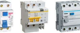
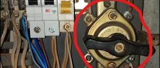
Circuit breakers installed in apartment electrical panels are designed for emergency power outages in the event of a short circuit or excess load on the circuit. They can also be controlled manually when it is necessary to change the switch.
The markings of the circuit breakers, presented in the form of names, alphanumeric designations and diagrams, will tell you what parameters the device has. Agree, the ability to “read” the inscription will be useful to the home handyman if he needs to replace a device, fix breakdowns, or connect an additional machine.
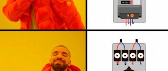
We will help you figure out what's what. The article describes a detailed explanation of the marking block on the switches, and also provides recommendations for choosing a machine, taking into account its characteristics.
Main themes
Marking of cable lines (cable tags)
Cable tags
SNIP 3-05-06-85 “Electrical devices”, put into effect on July 1, 1986 (Resolution of the USSR State Construction Committee dated December 11, 1985 N 215)
P. 3.22. Wires and cables laid in boxes and on trays must be marked at the beginning and end of the trays and boxes, as well as at the points where they are connected to electrical equipment, and the cables, in addition, also at route turns and branches. Marking of cable lines P. 3.103. Each cable line must be marked and have its own number or name. P. 3.104. Labels must be installed on exposed cables and cable joints. On cables laid in cable structures, tags must be installed at least every 50 - 70 m, as well as in places where the direction of the route changes, on both sides of passages through interfloor ceilings, walls and partitions, in places where cables enter (exit) into trenches and cable structures. On hidden cables in pipes or blocks, tags should be installed at the end points at the end couplings, in the wells and chambers of the block sewer system, as well as at each connecting coupling. On hidden cables in trenches, tags are installed at the end points and at each coupling. P. 3.105. Tags should be used: in dry rooms - made of plastic, steel or aluminum; in damp rooms, outside buildings and in the ground - made of plastic. Designations on tags for underground cables and cables laid in rooms with a chemically active environment should be made by stamping, punching or burning. For cables laid in other conditions, markings may be applied with indelible paint. P. 3.106. Tags must be secured to the cables with nylon thread or galvanized steel wire with a diameter of 1 - 2 mm, or plastic tape with a button. The place where the tag is attached to the cable with wire and the wire itself in damp rooms, outside buildings and in the ground must be covered with bitumen to protect it from moisture.
Rules for the construction of electrical installations (PUE) clause 2.3.23. Each cable line must have its own number or name. If a cable line consists of several parallel cables, then each of them must have the same number with the addition of the letters A, B, C, etc. Openly laid cables, as well as all cable terminations, must be equipped with tags indicating the brand, voltage, cross-section, number or name of the line on the tags of the cables and terminations; on the coupling tags - coupling numbers and installation dates. Tags must be resistant to environmental influences. On cables laid in cable structures, tags must be located along the length at least every 50 m.
“Rules for technical operation of consumer electrical installations” (PTEEP) 2.4.5. Each CL must have a passport, including the documentation specified in clause 2.4.2. dispatch number or name. Openly laid cables, as well as all cable couplings, must be labeled; the cable tags at the beginning and end of the line must indicate the brand, voltage, cross-section, number or name of the line; on the coupling tags - coupling number, installation date. Tags must be resistant to environmental influences. They should be located along the length of the line every 50 m on openly laid cables, as well as at turns of the route and in places where cables pass through fire-resistant partitions and ceilings (on both sides).
Marking tags are manufactured in accordance with TU 36-1440-82: Round tag (U-135) – intended for power cables above 1000V; Square tag (U-134) – designed for power cables up to 1000V; Triangular tag (U-136) – designed for control cables.
Examples of cable tags:
In accordance with the operating rules for electrical installations, any cable line must have digital and/or letter designations. Often, when an electrical circuit includes several parallel conductors, a combined alphanumeric system is used. In such a situation, the cable tag of each core contains the same numerical value, but different letters of the Cyrillic or Latin alphabet.
The cable sleeve and exposed wires must be marked with tags indicating the number, line name, operating voltage, cross-sectional area and brand of electrical components used. All tags are characterized by resistance to negative environmental factors. The maximum allowable distance between tags is 50 m.
Important connection points in the shield
The panel with all the correct markings for wires and cables looks like this:
Each group of electrical wiring must also be designated according to a certain principle:
- The letter "L" indicates the input wires.
- The letters "Gr" indicate groups.
- After the letters, numbers indicate the numbers of lines and groups.
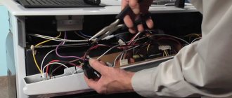
Don't forget about color codes, since mixed up colors often cause accidents. Sometimes, when opening a cabinet, you may not find any markings; in this case, you need to use probes to understand which wires serve which purposes.
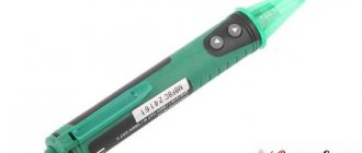
A screwdriver with an indicator will help you determine the purpose of the wires, with which you can easily find zero and phase. During the verification process, it is necessary to leave markings so as not to confuse the assignments of the conductors in the future.
It happens that you have to install conductors with markings of the wrong color that is required. In this case, remember about other markings on the ends of cables and wires; they must always be correct.
Insulating tape can also help make markings, but it is better to use the materials we wrote about above.
Heat-shrinkable tubes, which can also be used for marking, look like this:
Marking must be carried out not only in the panels, but also in the automatic control panels. This is necessary to distinguish different conductors, for example, to immediately identify signal cables and other conductors.
This is the basic information you need to know when marking conductors. Do not ignore the markings and follow the rules that we described in the article!
Marking with color and other symbols will help not only simplify repair work and maintenance, but also save human life and health during electrical installation work. In addition, the marking process does not take much time.
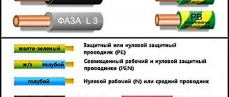
Coloring phase
In cases where the electrical installation is installed using rigid metal busbars, the tires are painted with indelible paint in the following colors:
- yellow – phase A (L1);
- green – phase B(L2);
- red – phase C (L3);
- blue – zero bus;
- longitudinal or inclined stripes of yellow and green color – grounding bus.
The color of the phases must be maintained throughout the entire device, but not necessarily over the entire surface of the bus. It is allowed to mark the phase designation only at the connection points. On a painted surface, you can duplicate the color with the “ZhZK” symbols for paint of the corresponding colors.
If tires are not accessible for inspection or work when there is voltage on them, then they may not be painted.
The color of phase wires connected to rigid busbars may not coincide with them in color, since there is a difference in the accepted designation systems for flexible conductors and rigid stationary distribution busbars.
What are cable tags made of?
A cable marking tag can have different sizes, which depends, among other things, on the amount of information placed on it. It can be made of various materials, but in any case, care must be taken to ensure that during installation the marking tag does not accidentally damage the wires.
You need to choose a soft material for making tags or make sure that hard marking labels (for example, metal) do not have sharp corners or jagged edges. This will help avoid damage to the insulating sheath of cables and wires.
Today, all marking tags available in the arsenal of electrical installation specialists are divided into three categories:
- classic cable with insert;
- solid plastic;
- made from PVC pipes.
Simple, time-tested and easy to use labels with insert. The necessary information is applied to the thick paper insert, after which it is simply inserted into the grooves on the tag.
The PUE is required to designate each electrical line in accordance with the regulations, regardless of where and in what way it is laid. If the power transmission route has several cable strands, then each of them is marked, indicating the main parameters and direction on the labels.
A tag is attached in front of each circuit breaker containing characteristics such as cable voltage and cross-section. The marking is applied to the labels with a marker that is resistant to external influences, including high temperatures. High-quality labels are not afraid of either corrosion or negative natural factors. They can be used both indoors and for outdoor electrical installations.
When laying the wire in a closed way, in a corrugated sleeve, the step for marking the wires should not exceed 50 meters. The labels are attached using plastic clamps or wire, firmly fixing them in the place selected in accordance with the PUE.
General information
There are many types of such equipment on sale. Prices, sizes, materials of manufacture will be found for any buyer and purpose. But first you need to understand what this electrical installation component is.
Purpose of the mounting box
Most people, when buying such equipment, pay attention only to the appearance of the product.
How it will look in the surrounding environment is, of course, important. But first of all, such boxes must meet the following requirements: But first of all, such boxes must meet the following requirements:
But first of all, such boxes must meet the following requirements:
- All installation and maintenance work is carried out under conditions that meet safety conditions.
- Metal enclosures are grounded.
- The material of the box must withstand temperature fluctuations, precipitation of all types, and solar radiation.
Plastic boxes are safer and look more attractive than metal ones. Such electrical installation devices go by different names. Some call them meter cabinets, others call them boxes. There is no single standard, and manufacturers define products in their own way. However, they all must be practical and convenient.
Most support mounting internal components using a standard DIN rail, allowing you to mount the equipment yourself. In addition to the meter, it is installed by trained specialists after receiving permission from the supervisory company.
Features of the box design
According to the rules, all protective boxes suitable for installation must comply with security levels from IP 20 to IP 65. In addition to size and color, they can be:
- Open installation.
- Secret.
- For floor mounting.
- For inline location.
- Invoices.
- Solid or collapsible.
Quality requirements
Even for such a simple-to-manufacture device as a box for an electricity meter in an apartment or on the street, high-quality execution of all its components is important. This will enable the owner to take readings comfortably and safely
When purchasing a metal cabinet, you need to pay attention to the following points:
To make the box itself, steel with a thickness of at least 1.2 millimeters is used. Thin iron will not provide sufficient strength and long-term use. Practice shows that the door of such shields is the first to sag. This violates the tightness of the structure and threatens the destruction of electrical devices installed inside. Industrial production involves testing finished samples in installations that simulate the most difficult weather conditions. If they pass the test, this means that the quality of the paint application is good and the sample will last a long time. Large manufacturers guarantee a service life of up to 15 years. Availability of a locking device. An outdoor box for an electricity meter must be selected with a lock that can be locked with a key. Its design can be any, the main thing is that there is a seal between the metal of the door and the cylinder. The thickness of the constipation is also important. The hole must be sealed. If there is a window for data control, then a seal is also needed here. Fastening must be provided with screws or self-tapping screws, since even the best glue dries out and the glass falls out. The cabinet door must be grounded. Since the first touch falls on it, if it is energized, you can get an electric shock with its help. Except for the door, the entire body is grounded
It is best if several bolts are provided for these purposes. Particular attention should be paid to the quality of seals. They are made of plastic rubber in the shape of a ring. There should be no breaks in it to avoid leakage. Semicircular bends along the edges of the door and body ensure a tight fit of the sealing gaskets, and if they break, they prevent water from getting inside.
There should be no breaks in it to avoid leakage. Semicircular bends along the edges of the door and body ensure a tight fit of the sealing gaskets, and if they break, they prevent water from getting inside.
Cable lines - marking requirements
Cable lines are an integral part of electrical and communication networks. When laying any open cables, including power cables in cable structures (cable tunnels, floors, overpasses, etc.), markings are required on the cable sheath. Power routes are often bundles of cables laid in parallel, the main purpose of marking which is ease of operation and repair of cable lines.
Unlike the factory marking of cable products, which is applied to the outer sheath and carries information about the features of the product, the marking of electrical installation cables is applied to explain the purpose of the cable. It must correspond to the information reflected in the cable log compiled when laying electrical cables. Labeling rules and the basic requirements for it are reflected in the following regulatory documents:
- current edition of the rules for electrical installations – clause 2.3.23;
- rules for technical operation of consumer electrical installations – clause 2.4.5;
- SNiP 3.05.06-85 – pp. 3.103 – 3.106.
According to the requirements of all three documents, marking is carried out by installing tags on laid cables and cable joints.
Features of cable line marking
Taking into account the above-mentioned tag rules, the following are established:
- at the beginning and end of the cable line;
- in places where couplings are installed;
- at points of change in cable direction;
- along the entire length of the line at a distance of no more than 50 m;
- on both sides where obstacles pass (walls, ceilings, etc.).
When laying cables in trenches, tags are installed next to the end couplings; in addition, they must be placed on the connecting couplings.
Tag markers installed along the entire cable line must contain the following information:
- cable number according to technical documentation;
- type of cable products used;
- the number of current-carrying conductors and their cross-section;
- numbers of cabinets between which the cable is connected, indicating the source and consumer;
- the length of the cable.
For connecting couplings, the marker indicates the number of the connection itself and the date when it was installed.
Tag markers differ in their geometry and material of manufacture. Due to their purpose, they come in square, round and triangular shapes:
- square mark the power cables of networks less than 1000 volts;
- round tags are used for marking high-voltage lines (from 1 kV and above);
- Triangles mark current-carrying lines of control cables.
Often, a bundle contains several dozen conductive lines; markers of this size get tangled, interfere with each other, and even get destroyed. In such situations, you can use smaller tags with a special fastening, which indicate only the cable number.
Tags are made from various materials: steel, aluminum or plastic. For rooms with high humidity or aggressive environments, only plastic tags are allowed. Today, a large number of building materials are produced, including those for electrical installations, so tags of any shape made of wear-resistant plastics or PVC are easier to buy.
Designations may be applied in any way that prevents abrasion or accidental damage to the inscriptions. This can be engraving on metal surfaces or burning with subsequent filling with dyes on plastic; for rooms with normal conditions, symbols are often applied with indelible paints. The simplest, cheapest and fastest way to apply information to tags today is considered to be the use of special printers.
The need for crimping flexible wires
If you install stranded wires, the core of which can contain from several to several dozen thin wires, under a screw or other fastening, only by removing the insulation, it will not be possible to achieve high-quality contact.
Read more…
Why loop grounding is prohibited
The resolution of the dispute is suggested by the rules for the installation of electrical equipment (PUE) clause 1.7.144, which prohibits the connection of protective conductors with a loop; however, the desire to save on expensive cables and installation work pushes many electricians to violate them. So what is the danger? Why are PUEs so uncompromising regarding daisy chain connections? Read more…
Alphanumeric markers
Most of the cables have letters and numbers on their surface. Each is responsible for a specific function or purpose. Symbols are necessary because there are special regulations for manufacturers, confirmed by regulatory documents.
It is worth noting that in modern conditions everything is created not according to standards, but according to technical conditions. What will be written may vary greatly depending on the field.
Designation of markings of power cables and electrical wires and their interpretation
These models differ in their characteristics - they contain conductors with a cross-section that can power the equipment. But remember that such equipment includes household consumers and at the same time serious devices in enterprises with enormous power.
To correctly decipher the letters on the surface, we provide a small list:
- If it starts with marker A, then the main part is aluminum. The absence of "A" indicates a copper element.
- B – stands after A or first if there is no A. Indicates the presence of insulation around a live part.
- B - reports a PVC insulating layer, can appear after the previous characters or 1 in the list.
- P - means that there is rubber around the core. HP subtype - will not support combustion.
- P – is responsible for the polyethylene sheath; in the case of cable products, this is a thermoplastic variety. They write Ps if it is self-extinguishing, Pv if it is vulcanized.
- If AC or AA are combined, then the second symbol means aluminum winding, and C means lead winding.
- K – armored galvanized steel under the hose part, but it is designated this way only if the abbreviation does not begin with it. If this is the first character, then it indicates that we have a control cable.
- B features an armored section made of a steel plate. If it has the addition Bn, then it is armor with a non-flammable coating, otherwise there is no cushion.
- G – if the letter is large, it means that this brand can be installed even in mine workings.
- d – small indicates that there is sealing. Usually the sealing layer is made with water-repellent tapes. 2g is an aluminum polymer base.
- Shv, Shp and Shps indicate that the coating is made of PVC, polyethylene or non-flammable hose.
- O - signals that everyone will have their own shell.
- ng - symbolizes that the material does not burn and does not burn in any way.
- E - if it is at the very beginning, then this is a model that will withstand placement in a mine and with particularly aggressive conditions.
For control models
Able to transmit a control signal to any device to which it is connected. It is used when it is important to obtain accurate data.
Explanation of the designation of the cross-section of cables and various wires of this category:
- K – belonging to the control group. It can stand in either 1st or 2nd place, indicating the material of the core.
- A – indicates the presence of aluminum. If there is no symbol, then the option in front of you is copper core.
- B - denotes polyvinyl chloride as insulation near the live part.
- c – the outer side is made of the same material.
- P - makes it clear that the insulating element was formed from polyethylene.
- F – fluoroplastic layer.
- P - indicates the presence of rubber as an insulator. HP is a rubber shell that will not support combustion.
- G – confirms that the selected model is naked.
- E - if not at the beginning of the line, then this is the screen in the composition.
It is worth noting that the KG coding usually marks not the cord for controlling devices, but the flexible cable.
For contact
For these lines, they came up with special brands that have their own markings for cable products and electrical wires. In standard cases, these are examples for small current, which have a small cross-section and a large number of pairs.
Descriptions are registered on them:
- T – telephone;
- P – polyethylene insulation;
- p – waist insulating material made of PVC or polyethylene terephthalate;
- P - if they come in a row, then this is an additional protective shell;
- E – screen, this is one of the elements required for signalmen;
- Z - indicates that there is a hydrophobic filler that will retain penetrating moisture;
- C – used only on railways.
How to decipher a digital designation
Usually 3 digits are used, which take on the parameters:
- how many lived - there is 1 or many, each is marked;
- cross-section - if there are conductors with different indicators, they are marked separately;
- shows the nominal voltage, but it is not always there.
How wires and various cords are marked
The principle by which markers will be placed on them differs from that used for cables. All requirements are specified in GOST 7399-97.
In this area, AC will mean that it is an aluminum core with a steel core. We are not talking about isolation here.
Requirements for inscriptions on tags
Tags on the cable, secured with clamps or threaded through the wire, must be signed in a certain way; this rule is regulated by the rules of the PUE. In accordance with this document, the following data is applied to the label:
- Cable or line number. This is information that contains data about the direction of the highway, what it feeds, and what level of protection is required. During the wiring installation process, an object passport is drawn up, which indicates the buildings or premises powered by this line. They are assigned numbers, which will subsequently be written on the tag itself; during the service process, the technician will be able to look at the markings of the cables and, by comparing them with the object’s passport, understand where this or that line leads;
- Brand and cross-section of wire. Since space on the tag is limited, the designation is written abbreviated, with a minimum number of characters. For example, a vinyl-coated cable with a cross-section of 3*2.5 is briefly designated VVG-3/2.5;
- Line voltage. This is a mandatory parameter, since it is not clear from the outer sheath of the cables what voltage the current flows through it, respectively, and what level of protection is required during repair work;
- The beginning and end of cable lines. For more accurate information about possible losses on the main line after its installation, a designation of the total length is applied. After reading the data, the technician servicing the wire line will be able to accurately calculate the resistance and level of voltage loss in the network.
Labels on tags
All of the information listed is basic and mandatory. It is not prohibited to place additional information on the tag that characterizes the electrical main, for example, the date of laying. In addition, when placing a tag on the coupling, it is necessary to place the date of installation of the wire, since the coupling has its own resource, which will be calculated based on this indicator.
Inscriptions on metal tags are most often made by engraving with a special pencil or indelible paint. Plastic products are signed with a permanent marker or indelible paint. Also, when placing a tag using wire on a highway, it is necessary to additionally protect metal objects with bituminous composition or any other paint, otherwise the wire will rust and collapse, and the tag will be lost. Nylon thread is best suited for fastening; it is not afraid of temperature changes and high humidity.
Tag for threading onto wire
Recently, to indicate the cable on the line, many electricians began to use stickers that already have inscriptions informing about the voltage, as well as empty spaces in which additional data is written. Such stickers are very convenient, since the master does not waste time making markings, but simply glues the element onto the finished tag and continues installation.
How to specify L, N, PE yourself?
If there is no visual designation or it differs from the standard designation, it is best to mark all the elements yourself after the repair is completed. To do this, you can use colored electrical tape or heat shrink tubing. According to the requirements, the indication of the cores must be done at the ends of the conductor where the connection to the bus is made.
Thanks to the color markings, repairs are made easier not only for you, but also for the electrician, who will most likely carry out repair work on the home electrical network after you! We talked about the process of marking wires in the shield in a separate article.
Basic requirements for marking wires in switchgears (switchgears) and switchboards
Clause 1.1.30 of the PUE states that all wires in the control panel must correspond to the alphabetic, digital and color designations. The presence of a color designation does not exclude the installation of numbers and letters. It is allowed to apply markings not along the entire length of the line, but only at the connection points.
Marking begins with compliance with the rules during the installation process, when connecting wires according to the color of the insulation. This is the most clear example, which allows operating personnel to quickly navigate the purpose of each individual wire in the circuit. Sometimes cables with wires of the same color are used; in these cases, it is possible to paint the ends of the wires, put on cambrics of the corresponding color, or it is more practical to install a heat-shrinkable tube with alphabetic and digital values already applied. The length of the marker tube must be at least 2.5 cm.
Wire marking by color
In three-phase networks, each phase is designated by the letters A, B, C, but in apartments and private houses single-phase power supply circuits are used, so there is no point in specifying which phase of the substation your panel is connected to.
Letter designations:
- The phase wire is marked with the letter “L”;
- The neutral wire is designated by the letter “N”;
- Grounding wires are marked with a symbol
- In circuits according to TN-CS system standards, it is allowed to connect the grounding conductor to the neutral wire. In such cases, “PEN” is written on the label.
- In DC power supply circuits, for individual consumer devices the polarities “+”, “-” and the voltage in volts “12V or 24V...” are indicated.
Marking DC circuits
Features of operation of network protection circuit breakers
Whatever class the circuit breaker belongs to, its main task is always the same - to quickly detect the occurrence of excessive current and de-energize the network before the cable and devices connected to the line are damaged.
Currents that may pose a danger to the network are divided into two types:
- Overload currents. Their appearance most often occurs due to the inclusion of devices in the network, the total power of which exceeds what the line can withstand. Another cause of overload is a malfunction of one or more devices.
- Overcurrents caused by short circuit. A short circuit occurs when the phase and neutral conductors are connected to each other. In normal condition they are connected to the load separately.
The design and principle of operation of the circuit breaker is on video:
https://youtube.com/watch?v=9bTw3wtgOWY
Overload currents
Their value most often slightly exceeds the rating of the machine, so the passage of such an electric current through the circuit, if it does not drag on for too long, does not cause damage to the line. In this case, instantaneous de-energization is not required in this case; moreover, the electron flow often quickly returns to normal. Each AV is designed for a certain excess of electric current at which it is triggered.
A thermal release, the basis of which is a bimetallic plate, is responsible for turning off the power under the influence of a powerful load.
This element heats up under the influence of a powerful current, becomes plastic, bends and triggers the machine.
Short circuit currents
The flow of electrons caused by a short circuit significantly exceeds the rating of the protective device, causing the latter to immediately trip, cutting off the power. An electromagnetic release, which is a solenoid with a core, is responsible for detecting a short circuit and immediate response of the device. The latter, under the influence of overcurrent, instantly affects the circuit breaker, causing it to trip. This process takes a split second.
However, there is one caveat. Sometimes the overload current can also be very large, but not caused by a short circuit. How is the device supposed to determine the difference between them?
In the video about the selectivity of circuit breakers:
Here we smoothly move on to the main issue that our material is devoted to. There are, as we have already said, several classes of AB, differing in time-current characteristics. The most common of them, which are used in household electrical networks, are devices of classes B, C and D. Circuit breakers belonging to category A are much less common. They are the most sensitive and are used to protect high-precision devices.
These devices differ from each other in terms of instantaneous tripping current. Its value is determined by the multiple of the current passing through the circuit to the rating of the machine.
What else is important to know
The photo below shows the board in which the wires were marked during installation:
When assembling an electrical panel, electrical wiring groups should be marked as follows: the input wire is marked as L, and the output wire is marked Gr (indicates that these are groups). After the letter the group number and line number are indicated.
Also, during marking, it is important to take into account all color differences so that an emergency situation does not arise. If, after opening the cabinet, no markings were found, then you need to use a probe to determine where each wire is located.
We talked about how to use an indicator screwdriver to determine phase and zero in the corresponding article. Since this will take a lot of time, it is better to leave marks when checking so that another electrician who will carry out repairs or maintenance can understand where which wire is.
If there are no conductors of the required color, then you can use any color, as long as the ends of the cores are correctly marked during installation. This can be done using colored electrical tape or special heat-shrinkable tubes.
Heat shrink markings look like this:
This is the technology used to mark wires and cables when installing an electrical panel
As you can see, marking the lines is very important, and the process itself does not take much time
Please note that with the help of these instructions you can mark conductors not only in power electrical panels, but also in automation panels (for example, to mark signal cables and control)
It will be useful to read:
Production time
Depends on the size of the shield and its composition. Typically, the production of markings for boards for 24, 32, 48 modules takes 1-2 days.
1000-2000 rubles for shields of 24-48 modules.
Rails in the shield Modules occupied Cost:
1230 rub. for a panel with two rails of 12 modules each.
Payment for individuals: to order, an advance payment of 100% is required to a Sberbank or Alfabank card.
Unavailable payment methods: cell phone and electronic money.
Wire tags printed on a cable printer
We have such a cabinet to control the pumping station:
Control cabinet - wires are not labeled, tags are needed!
Scheme:
Diagram of installation of water supply to the workshop
The circuit is simple, however, if you approach it for the first time, it will take time to figure out which wire is which. Therefore, wire tags are vital!
As a result, wires with stickers (tags) look much clearer:
Wires with tags printed on a BROTHER P-Touch printer
Labels on the control panel wires - it makes everything much easier!
I printed a test label on the pipe in a small font size on 9mm tape. It would be necessary to reprint it larger.
Sticker on water supply pipe, printed on BROTHER P-Touch
What else is important to know
The photo below shows the board in which the wires were marked during installation:
When assembling an electrical panel, electrical wiring groups should be marked as follows: the input wire is marked as L, and the output wire is marked Gr (indicates that these are groups). After the letter the group number and line number are indicated.
Also, during marking, it is important to take into account all color differences so that an emergency situation does not arise. If, after opening the cabinet, no markings were found, then you need to use a probe to determine where each wire is located.
We talked about how to use an indicator screwdriver to determine phase and zero in the corresponding article. Since this will take a lot of time, it is better to leave marks when checking so that another electrician who will carry out repairs or maintenance can understand where which wire is.
If there are no conductors of the required color, then you can use any color, as long as the ends of the cores are correctly marked during installation. This can be done using colored electrical tape or special heat-shrinkable tubes.
Heat shrink markings look like this:
This is the technology used to mark wires and cables when installing an electrical panel
As you can see, marking the lines is very important, and the process itself does not take much time
Please note that with the help of these instructions you can mark conductors not only in power electrical panels, but also in automation panels (for example, to mark signal cables and control)
It will be useful to read:
How to choose a circuit breaker for your home: by power, by current
Any electrician will say: “If there is no urgent need, it is better not to get into the electrical wiring of the house with your own hands.” The consequences can be dire. When does such a need arise?
In order to change the socket, you need to know physics in grades 8-9. With other electrical components, everything is a little more complicated. If a circuit breaker in your apartment regularly trips (the circuit breaker in the panel) and the light goes out, it’s time to change it.
Probably, the circuit breaker has exhausted its service life, even though the period specified in the passport has not yet expired. A worn-out 16 A device may operate at low load on the network (10 A), or may not operate at extreme values (contacts will solder together, and then there will be a fire).
Just in case, let us recall some information from the school curriculum:
- Power = Voltage x Current.
- Current = Power Voltage.
The voltage in the socket is 220 V. The coffee maker indicates 1200 W, which means the current consumption will be 1200220 = 5.45 (A).
If you managed to add up the power of all household electrical appliances and calculate the total current, you can consider yourself a second-level electrician.
Externally, the circuit breaker is a plastic box with terminals for connecting wiring, plus a toggle switch. There is no need to go inside. It is important for us that it contains contacts, thermal and electromagnetic releases, which are responsible for de-energizing the network under increased and extreme loads.
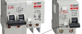
How to decipher the markings on a circuit breaker:
- The letter (A, B, C, D) is the class of the machine; it means the limit of the instantaneous operation current, that is, the voltage when the machine immediately de-energizes the network in the apartment. In most cases, in residential buildings there will be a machine with the letter C. It will instantly operate at a 5-10 times increase in current from the nominal value. That is, a machine with a rating of 10 A will turn off the network without delay at a current value of 50-100 A. A machine with a B-characteristic (3-5 times the excess) will do the same at a value of 30-50 A.
- The number indicates the rated current, that is, the value up to which the machine will operate in normal mode without turning anything off. The same 10 A circuit breaker, if the current exceeds 11.5, will work only after two hours. At 14.5 it will wait a minute, if the network overvoltage does not disappear, it will de-energize the apartment. And so on, until the peak values indicated by the letter, when the network drops without delay.
- Next to it, in a smaller font, there will be another number (in thousands of amperes), indicating the maximum current value at which the machine will operate without being damaged.
What is the trick here, why can’t you immediately turn off the network if the nominal value is exceeded? The machine takes into account short-term currents that occur in the network for a split second when electrical equipment is turned on. When you turn on the washing machine, the starting current may be 2-3 times higher than the rated current.
The main function of a circuit breaker is to protect the network from short circuits and overloads. When too much current flows through a line, the wiring becomes hot. If this happens for too long, the wire may catch fire.
By and large, the machine doesn’t care about your electrical appliances; contrary to popular belief, it does not protect them from power surges. But losing a microwave or kettle connected to an outlet is one thing, but burnt out wiring in a wall or chandelier is another.
It is important to understand that the machine will not protect you from electric shock if you accidentally touch live areas or grounded objects. For this purpose, there are residual current devices (RCDs). It is advised to place one general one after the introductory machine and for groups where there is a risk of electric shock.
In order to choose the right circuit breaker, you need to estimate the maximum permissible current load of the network (sum up all devices). The denomination of the machine (the number after the letter) should not exceed this value.
For an ordinary apartment where there are no “serious” power consumers such as an air conditioner or water heater, a class B machine is suitable. Such a network is considered lightly loaded. It is dangerous to install a high-load circuit breaker (class D) for a network that powers light bulbs. He will not perceive voltage surges in it as harmful and can even miss a short circuit.
A lightly loaded device in a network with a heavy load in normal mode, on the contrary, will operate inappropriately and often.
Yes, we almost missed it: machines differ in the number of phases (poles). The number of poles of the machine indicates which type of network it can work with.
You can also install one class C input switch and one single-phase switch in the apartment to provide separate areas (kitchen, room, separately for air conditioning, if provided).
If you don’t want to complicate things, in a two-room apartment you can get by with one circuit breaker B with a rating of 16.
We have almost figured out how to choose a circuit breaker based on current and power. But if you consider only the load of consumers, you can run into trouble. The choice of machine directly depends on the type of wiring and cable. If the wiring is weak, a powerful automatic machine will not cope with its tasks when overloaded.
In houses before 2001-2003, there will most likely be aluminum wiring in single-layer insulation.
Most likely, it has already served its purpose (nominally it can withstand 20 years under ideal conditions, without overload).
It is categorically not recommended to install a new machine on it, taking into account only the total power of consumers. The automatic machine will stop working frequently, but the problem of overheating will remain.
There are essentially two options:
- Change the wiring to copper.
- For powerful consumers (washing machine, boiler, air conditioner), draw a separate line from the panel and install a separate machine on it.
READ MORE: Artel air conditioner errors: decoding fault codes and tips for eliminating them
Copper wire carries more current than aluminum wire. But here, in addition to the material, it is important to take into account its cross-section. It lets you know how many amps can be passed through the cable without fear of damage or overheating.
For example:
- Aluminum wire with a cross-section of 2.5 mm2 safely operates with currents up to 16-24 A.
- Copper wire with a cross-section of 2.5 mm2 safely operates with currents of 21-30 A.
This means that with a load of 23 A, a machine rated at 16 A will de-energize the wiring in a minute. It is enough to prevent the copper wire from overheating.
If you install a 25 A circuit breaker, before disconnecting the cable will carry current beyond its normal load, it will overheat, the insulation will wear out faster, and the socket will burn out over time.
For aluminum wiring, accordingly, these values are lower.
For ease of understanding, we offer a table for selecting a circuit breaker based on the cable cross-section.
Last piece of advice: you shouldn’t skimp on your safety. It is better to buy machines from specialized stores and choose manufacturers with a proven reputation. On-site managers will answer questions that we may have missed in this article.
If previously there was such a switch in the network, it was only at the entrance of the wiring to the house.
Now they are installed on different branches of the house network, supplying electrical energy to certain consumers.
Typically, the home owner's knowledge about these switches boils down to the fact that they protect devices connected to the network or one of its branches from overload.
And this is true, but this is only a consequence of the operation of this device.
The main purpose is to protect wiring from excess current values, primarily critical ones.
In short, if the current is exceeded, the switch will de-energize the part of the wiring that is attached to its output terminals. But its operation may be different.
But in case of a sharp jump, which usually occurs during a short circuit, the switch will operate almost instantly, which will protect the wiring from melting and a possible fire.
If we look at the circuit breaker externally, we don’t see much complexity in its design – just a plastic box with terminals for connecting wiring and a small toggle switch for turning it on and off.
But this is only external.
Its internal design is not so simple.
The housing contains:
- Cocking mechanism;
- Thermal installation screw;
- Bimetallic thermal release;
- Electromagnetic coil release;
- Arc chamber;
- Power contacts;
- Exhaust channel for hot gases.
Each of these elements performs a specific job. Read on the topic - what is a difavtomat, how to connect it.
The cocking mechanism is connected to a toggle switch, and power contacts are installed at its ends. They transmit electric current from the incoming terminals to the outgoing terminals.
A bimetallic (thermal) release is a plate that bends when heated, disconnecting the power contacts.
Important
This release is designed to stop the current supply if its strength does not have a peak value.
If the current is slightly exceeded, over time the plate will heat up and the contacts will open. That is, this release is triggered after a certain time.
The screw adjusts the gap between the plate and the contact. This screw is adjusted at the factory.
The electromagnetic release is designed to instantly de-energize the network. It operates only when exposed to high currents that occur during a short circuit.
When one of the releases is triggered, an electric arc will inevitably occur between the contacts, and the greater the current, the stronger it is.
To prevent this arc from leading to damage to the elements of the switch, its design includes an arc suppression chamber, which extinguishes the resulting arc within itself.
With all this, gases with elevated temperatures are formed inside, which are discharged through a special channel.
Advice
Structurally, all circuit breakers are almost the same, but their operating parameters differ.
There are certain criteria for selecting circuit breakers, which take into account their parameters.
Short circuit current.
The first criterion that is taken into account when choosing a machine is the short-circuit current, which is also the breaking capacity of the circuit breaker.