The supply of electricity to the house is handled by the relevant organization. This type of work is associated with certain risks (all operations are carried out without removing the voltage), so electrical safety rules must be strictly observed. The choice of cable for introducing electricity into a private house (section, number of cores, material) lies entirely on the shoulders of the owner of the site. The durability of the electrical network in the house directly depends on this choice, so you should approach the work very seriously.
Cable entry can be carried out by air - from the pole to the house. But they also resort to introducing the cable into the house through the foundation, underground.
Subscriber branch: concept, principle of operation
On each street there are main power lines, the voltage through which comes from the nearest transformer substation. A higher potential difference of 6 or 10 kV arrives at the transformer. But this information is solely for general development, since the main line voltage is 380 V, and between the phase and the neutral wire - 220 V.
To lay a cable from a pole to a separate consumer - a private house, it is necessary to install a subscriber branch from the main line. A subscriber branch is the supply of electricity to an individual consumer. With this procedure, you must correctly calculate the wire through which the electricity will be supplied.
Administrative and legal nuances
The supply of electricity to a private home must be carried out by electricians with a certain access group.
To introduce electricity into the premises, the owner must obtain permits from the energy supply. The basis for the permit is the PVE project, which describes the internal electrical network in detail and provides calculations of consumer power. After this, the parameters of the allocated power and the consumer limit are set. According to the PVE, technical conditions are determined - connection method, communications features, engineering aspects.
Electrical distribution teams, the owner or a licensed contractor can connect the house to electricity.
Required documents
Example of a response to an application for technological connection
The property owner sends a request to the selected network organization. The company reviews the application within 15 days. After a positive response, the following documents are prepared:
- application for technical connection in a unified form;
- diagram of power receivers;
- copies of documents on the right to a building or land plot;
- an application indicating the citizen’s full name, passport details, location of receivers, time frame for creating the project and putting the line into operation, name of the provider, permit for construction work.
After reviewing the documents, the energy provider sends a contract with technical conditions. The applicant remains to sign it and send it to representatives of the network organization.
If the site meets the requirements of the technical conditions, work on its territory is carried out at the expense of the owner. Events outside the allotment are paid for by the network company. Upon completion, the energy sales company connects the premises to the network after a control inspection.
How cable tension is done
After fixing the conductor on special rollers, begin to tension it. This requires the following tool:
- hand winch;
- stretching device;
- dynamometer.
The hand winch is attached to the nearest support using anchor bolts, and the cable is pulled along it using a tensioning device. The tension force is regulated by technical documentation and is controlled using a dynamometer.
Grounding systems (GS)
According to the main provisions of the PUE, the grounding of electrical installations and working equipment can be organized in several ways, depending on the neutral connection circuit at the transformer substation.
Based on this feature, there are several types of grounding systems, designated in accordance with generally accepted rules. Their classification is based on a combination of the Latin symbols “T” and “N”, which means the transformer neutral grounded at the substation.
The letters “S” and “C” added to this designation are abbreviations from the English words “common” - common gasket and “select” - separate. They indicate the method of organizing the grounding conductor along the entire length of the supply line from the substation to the consumer (in the first case - a combined PEN, and in the second - separate PE and N).
Combined with a hyphen “CS” means that on some part of the route the grounding conductor is combined with the working “zero”, and on the remaining section they are laid separately.
Subscriber branch cable cross-section
The regulated procedure for laying conductors through the air is specified in the rules for electrical installations. The requirements of the rules are established for power lines with voltages up to 1000 V.
Calculations of the cable cross-section should be based on the operating mode: normal, emergency or installation. Since the branch is standard, you should select the normal (nominal) mode. The PUE provides for the minimum permissible wire cross-section:
- It is allowed to use a wire made of a standard aluminum alloy (not heat-treated) with a cross-section of at least 25 mm².
- When using a conductor made from a combination of steel and aluminum (heat-treated), its cross-section should also be 25 mm².
- If a copper wire is laid, its cross-section can be 16 mm².
The above indicators are suitable for standard ice wall thicknesses of no more than 10 mm. If the thickness reaches 15 mm and above, then the cross-section of the aluminum and steel-aluminum cable remains unchanged, and the copper conductor must be increased to 25 mm².
Information is presented in Chapter 2.4 of the PUE.
Rules for grounding pipelines
Grounding of pipelines is a mandatory measure, enshrined in the PUE. This is how you can increase the safety of their operation, because static electricity accumulates in pipe systems, plus there is always the possibility of lightning striking the pipes. The requirements of the rules for the construction of electrical installations are to provide grounding not only for external pipelines, but also for internal ones (technological and communication).
The PUE clearly regulates how pipelines should be grounded.
- Firstly, the pipe system must be a single continuous network connected into a single circuit.
- Secondly, pipelines must be connected to the grounding system at at least two points.
As for the first position, this does not mean that the pipeline system itself must be continuous. Here it will be enough to ensure the connection of sections or individual pipelines into one single network, for which so-called wafer jumpers are most often used. In fact, this is an ordinary copper wire of the brand either PVZ or PuGV. Fastening of jumpers to the pipeline is ensured by welding, bolting, or a grounding clamp for pipes is installed.
As for the second position, experts recommend not to scatter along the entire line of the technological chain, just to make a connection at the beginning and end of the circuit.
The main operating parameters used to calculate the cable
To connect the cable to the house, you need to decide on its cross-section. The cable cross-section is its area at the cut site. Generally accepted standards (according to the PUE) are indicated in the previous section. The main operating parameters by which the cable cross-section is selected are its cross-section and rated current.
But in addition to the cross-section, a certain conductor material is also needed. Nowadays, copper wires are most often used; they have lower resistance, but are more expensive. Aluminum does not have such high conductivity, but its price is lower than that of copper products. It should be remembered that with the same load, the cross-section of the aluminum conductor should be larger than that of copper.
And the last parameter is the number of cores, but with this everything is much simpler. When introducing only one phase and a working zero into the house, a two-core cable is used; when introducing three phases and a zero, a four-core cable is used. In both options, the cross-section of the zero conductor may be smaller than that of the phase conductor.
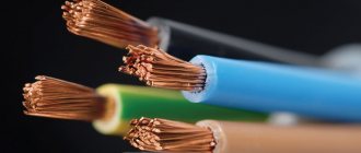
Features and color of electrical wires
Painting in a variety of colors is needed to make it easier to distinguish conductors during installation of a multi-core cable. It may be noted that a couple of decades ago, color marking did not matter. Nowadays, most people adhere to the meaning of wire according to color scheme in everyday life.
There are cores running through the cable, each of them has its own purpose and its own characteristic color. With the current variety of colors, installation work is easy and calm. Coloring is a useful feature to avoid dangerous and unnecessary mistakes. The state has established rules and regulations for labeling:
- The phase is indicated by a red, black, gray or brown tint.
- The neutral conductor is identified by blue color.
- The ground (ground wire) is yellow-green in color.
In addition to the color difference of the cable, there is also a marking indicated by letters:
- N - neutral or middle conductor;
- PE - zero (protection);
- PEN - classic combination of wires, combined zero;
- L - phase conductor.
From time to time, three-core cables at home are laid from flat conductors of the same color; they are often made in white. In this type of use, the core running through the middle will be considered grounding. Manufacturers often designate the insulation of the ground conductor in yellow and green. It is also possible that the yellow-green coloring will be applied transversely.
When performing repair work yourself, it is advisable to choose what color the ground wire will be and use a marker to apply the selected color to the wiring yourself for easy identification of cables in the future. As an alternative to a marker, you can use silicone tubes of the desired color; they are sold in almost every electrical store.
Having decided what color the grounding wire will be, you need to select the material for making the core. For grounding in domestic conditions using a stranded or single-core wire, it is necessary to use copper conductors. The cross-section of the grounding cable is selected in accordance with the requirements of the home network.
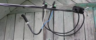
Cable laid over the air
The main type of installation of the input cable is its installation by air. Air input has its advantages:
- Minimum labor costs.
- It takes a short amount of time to connect your home. It is rare that such work takes more than two hours.
- Low cost of consumables: anchor bolts or clamps, special brackets, insulators.
- Possibility of quick troubleshooting, even if the entire cable needs to be replaced.
The following types of cables are used for aerial installation:
- SIP cable is a self-supporting insulated wire.
- Non-insulated, material - aluminum.
- Bare aluminum with steel core.
Comments:
Step
An intelligent article, described in some detail, thanks to the author. But fastening it with tapes to the support every 50 cm is overkill. It is not necessary. According to the PUE, this distance is 100 cm and is sufficient to firmly hold the cable.
Larion
So I counted the current collectors. Can you tell me how much cable power reserve should be taken in order for the whole system to work?
Magomed
Larion, ideally, the more, the better. The more powerful the cable is installed in your home, the less likely it is that it will ever fail. More power means longer service life.
Leave a comment Cancel reply
Similar posts
Features and some secrets of installing open wiring in a wooden house with your own hands
Features and scope of use of multi-core flexible copper cable Retro wiring in a wooden house - functional features, as well as the secrets of its creation
Legrand cable channel will help organize any cables in the office
How to choose the right section and brand of SIP
So what kind of cable should be used to bring electricity into the house? Many people resort to using SIP cable; it is allowed in many electrical industries and even in high voltage lines up to 35 kW.
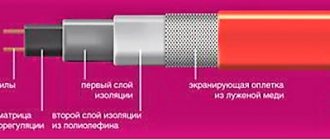
This cable has its own design feature - phase wires, most often in the amount of three, wrap around the fourth - zero. Therefore, the appearance of SIP resembles a rope twisted into a spiral. High-quality LDPE or XLPE polyethylene is used to insulate conductors. These types of materials have high resistance and a long service life, which allows them to be used even with sudden temperature changes.
The core, which is located in the middle and has zero potential, is made of aluminum alloy. Sometimes the zero does not have its own insulation, which is required for phase conductors.
The SIP cable has one serious drawback - due to the presence of insulation, the cable is insufficiently cooled, so the current loads allowed are lower than those of uninsulated conductors. When choosing SIP, you should pay attention to insulation:
- With insulation made of thermoplastic polyethylene, temperature loads of up to 70 degrees are allowed. Suitable for this parameter: SIP-1, SIP-1A, SIP-4, SIPn-4.
- When choosing cross-linked polyethylene as an insulating material, temperature loads of up to 90 degrees are allowed. Overload mode indicators and short circuit current parameters also increase. Such performance characteristics have: SIP-2, SIP-2A, SIPs-4, SIP-3, PEV and PEVG.
The SIP cross-section is also determined by power consumption, the formula is presented above.
For mobile equipment
There are other systems for organizing protective grounding of equipment (TT and IT, for example), which use a neutral conductor as a “zero” conductor and involve the arrangement of a re-charger on the consumer side.
In the first case, the neutral at the substation is solidly grounded, and in the second, it is not connected anywhere at all. These options for switching on the neutral are rarely used and only in cases where it is necessary to re-ground mobile electrical installations (provided that this is very difficult to do on the generator side).
According to GOST 16556-81, the IT system discussed above is used for mobile electrical equipment, during the implementation of which re-grounding is organized on the consumer side. This standard specifies the technical characteristics and parameters of the storage facility, which is temporarily installed in the area of upcoming work.
Cables for laying in the ground
When choosing a wire for underground input into a house, you should pay attention only to high-quality and reliable products, since a very common problem with such input is a breakdown to the ground.
Modern cables, made specifically for installation in the ground, have the following insulation:
- Pressed paper with special impregnation.
- Polyethylene.
- Polyvinyl chloride.
Very often they use VBBShV or PvBSHV conductors, which in addition to standard insulation have strip armor. AABL cable is also popular, but has a lower cost, since its shell is made of aluminum. Where there are risks of damage, PvKShp with wire mesh is most often used.
Specifications
As soon as all the necessary documents have been submitted, technical documentation is issued to the owner of the plot within a month. conditions, with the designation:
- power grid – standard 16 kW,
- a list of devices used to record consumed resources (meters),
- input switch,
- equipment devices that provide protection when using the network,
- the presence of a box that ensures the tightness of the equipment contained in it for connection from the outside.
Attention! Technical specifications are the main document indicating the preparation of the project. Only from the moment of studying those
conditions, it is allowed to supply light to the site, since this document is a key element in the preparation of a project for supplying the site with electricity
Only from the moment of studying those. conditions, it is allowed to supply light to the site, since this document is a key element in the design of a project for supplying the site with electricity.
How does electricity enter the house?
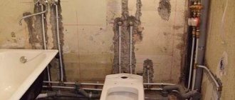
When introducing electricity into a private house, use one of the previously presented methods (laying a cable through the air on a cable or in the ground). When supplying electricity to a house, you must strictly follow the basic rule - the input cable should not have transits. The panel in which the consumer circuit will be presented should be located near the input cable for easier installation.
The conductor cannot be installed indoors directly through a hole in the wall. The hole must have additional protection; usually a metal pipe is used for this. The diameter of the pipe should be taken with a reserve, and the free space between the cable and the walls of the pipe should be sealed with cement mortar.
Ways to organize wiring inside the house
There are several options for performing internal wiring.
Connecting different cables inside
Welding the wire
The SIP conductor is broken and connected to the VVGng cable by twisting and strengthening by soldering. The technique is not reliable, as it can lead to fires.
Connecting various conductors with fittings
The coupling of SIP and VVGng is carried out using standard reinforcing bars, piercing clamps or other elements near the insertion point. It is unacceptable to use SIP in a residential area - it supports combustion processes.
Through the difavtomat
The connection diagram provides for the use of a two- or four-pole differential circuit breaker. The device is located in a separate sealed box. The cable is laid from the main line to the box and connected to VVGng in a corrugation.
To increase protection, a machine with a rating higher than the distribution board is used. This way, if there is a short circuit or overload, you can restore the line without leaving your home. Another device is installed outside, de-energizing the internal cable and preventing fire.
Electrical lines can be introduced into a residential building by air or underground. Before starting work, it is necessary to obtain permits and select a SIP cable and its cross-section.
How to make the correct air injection
When introducing a cable into a house from a nearby line or pole, you should invite specialists. To attach it to the wall, you must use special overhead brackets (especially when installing it in a wooden house). This will allow you to securely fix it and not damage the insulation. At a certain distance from the wall, a slight deflection of the cable should be made in order to prevent rainwater from entering the room.
The cable on which the cable is attached must not be overtightened on the supports, since during sudden and frequent temperature changes (which occur during cold periods of the year), it can become deformed.
Types of material (profiles)
According to the requirements of the PUE, which contain instructions on what the resistance of current flow in the ground should be, in most cases this indicator is set at a level of no more than 4 ohms. To obtain this value, you usually have to make a lot of effort to adhere to the same technology requirements.
First of all, this concerns the materials used in assembling the grounding loop, selected based on the following conditions:
- When choosing pins, preference should be given to ferrous metal blanks;
- The most commonly used rod is a standard size of 16-20 mm or a corner with parameters 50x50x5 mm and a metal thickness of about 5 mm;
- It is not allowed to use reinforcement as circuit elements, since it has a hardened surface that affects the normal flow of current;
- For these purposes, it is pure rod that is suitable, and not its reinforcement substitute.
Note! For areas with dry summers, thick-walled metal pipes are best suited, the lower end of which is flattened into a cone, and then several holes are drilled in this part of the pipe. According to the provisions of the PUE, before placing them in the ground, holes of the required length are first drilled, since driving them manually is quite problematic
In the case of a particularly dry summer and a sharp deterioration in the parameters of the ground electrode, a concentrated saline solution is poured into the hollow parts of the pipes, which makes it possible to obtain the resistance that should be in accordance with the requirements of the PUE. The length of pipe blanks is selected within 2.5-3 meters, which is quite enough for most Russian regions
According to the provisions of the PUE, before placing them in the ground, holes of the required length are first drilled, since driving them in manually is quite problematic. In the case of a particularly dry summer and a sharp deterioration in the parameters of the ground electrode, a concentrated saline solution is poured into the hollow parts of the pipes, which makes it possible to obtain the resistance that should be in accordance with the requirements of the PUE. The length of pipe blanks is selected within 2.5-3 meters, which is quite enough for most Russian regions.
This type of profile blanks has special requirements regarding the order of their placement in the soil and consists of the following:
- Firstly, the pipe elements of the protective circuit must be placed at a depth exceeding the soil freezing level by at least 80-100 cm;
- Secondly, in particularly dry areas, approximately a third of the length of the ground electrode should reach wet soil layers;
- Thirdly, when fulfilling the second condition, one should focus on the peculiarities of the location of the so-called “groundwater” in a given region. If they are located at a significant depth, according to the rule formulated in the provisions of the PUE, it will be necessary to prepare longer pipe sections.
The type and profile of the pin blanks used in the construction of the grounding switch can be found in the figure below.
Acceptable pin profiles
In practice, in most regions of Russia, a steel corner and a strip of the same metal are usually used. In order to obtain more accurate parameters of the grounding elements used, geological survey data will be required. If this information is available, it will be possible to involve specialists in calculating the parameters of the ground electrode.
What is metal bonding made of?
The elements connecting the pins (metal bond) are usually made of the following electrical materials:
- A typical copper busbar with a cross-section of less than 10 mm2;
- Aluminum strip with a cross section of about 16 mm2;
- Steel strip 100 mm2 (standard size – 25x5 mm).
Classic metal ties are usually made in the form of steel strips cut to size and welded to the corners or heads of the rod.
Important! The quality of the welding joint determines whether this grounding device or circuit can pass verification tests for compliance of the contact resistance with the standardized value (4 Ohms)
When using more expensive aluminum (copper) strips, a bolt of a suitable size is attached to them for welding, on which the supply busbars are subsequently fixed
The main thing you need to pay attention to when arranging any connections is the reliability of the resulting contact
To do this, before preparing the bolted joint, it is necessary to thoroughly clean both parts to be connected until the shine of clean metal appears. Additionally, it is advisable to sand these places, and after tightening the bolt, tighten it well, which will ensure more reliable contact.
Some examples of input cable protection
The best protection for the input cable is its insulation and the method of laying it in a place where no one can reach it. This can be a method of laying underground or by air. To prevent the harmful effects of natural conditions, the conductor can be laid in a special PVC pipe, but few do this, due to the significant increase in the cost of the structure.
To protect the wire in the wall, it is best to use a metal pipe. A replacement for metal can be PVC, which has a more affordable price.
Rules for preparing a package of documents
This package includes the following papers:
- identification document of the owner (passport). When performing work from a trusted person, a power of attorney certified by a notary is required;
- certificate of ownership of the land plot;
- a specially prepared drawing of the site indicating the nearest power line pole;
- diagram indicating the placement of technical equipment, gas and water pipes.
Modern innovations allow you to use the Internet, a map of your site in Yandex or Google, and mark the border of your site. Such formats are quite accessible for delivery to organizations. The standards require that if a post is located more than 25 meters from your boundary, it will be your responsibility to install an additional post.
If all standards are taken into account, you can safely begin connecting the site to electricity. Based on the collected documents, the regional power grid company issues technical specifications according to which the entire scope of work will be carried out.
After submitting the papers within a month, the owner receives a technical specification where the following parameters are precisely indicated:
- network power, usually 16 kilowatts;
- list of electricity metering devices (electricity meters);
- input switch;
- installation of protective equipment;
- the presence of a sealed box in cases of external connection.
Technical instructions are the main document confirming the preparation of the design part.
If the owner does not have enough time, then it is possible to contact a specialized company that will solve for you all issues related to the preparation of permits.
Cable entry underground
A wire laid underground does not require fastening to the wall; in this case, the conductor is laid through the foundation. The part of the cable that comes out of the ground must be protected using a metal tube or a thick PVC conduit.
To lay a cable in the ground, a trench must be made, at least 70 cm deep. At the bottom of the trench, a sand “cushion” is made, 15–20 cm thick. The cable is laid on it and closed with earth on top. Underground cable entry is a labor-intensive process, but more durable than overhead entry.
Cooperation with Cablestar
If you need it, just call our company and place an order. We have a large selection of high-quality cable and wire products. In stock you can find VVGngLS cables, (including) and other brands of wires. If you need detailed professional advice, the company’s specialists are ready to provide it. Contact us by phone or leave requests on the website, online, and consultants will help you choose the appropriate cable, as well as place your order. We always focus on the needs and preferences of our clients.
In our company, favorable terms of cooperation await you. We offer all customers the best prices and guarantee full compliance of cable and wire products with all declared properties and characteristics.
the site responds
2.3.71. Cables with metal sheaths or armor, as well as cable structures on which cables are laid, must be grounded or neutralized in accordance with the requirements given in Chapter. 1.7.
2.3.72. When grounding or neutralizing the metal sheaths of power cables, the sheath and armor must be connected by a flexible copper wire to each other and to the housings of the couplings (end, connecting, etc.). On cables of 6 kV and above with aluminum sheaths, grounding of the sheath and armor must be carried out with separate conductors. It is not required to use grounding or neutral protective conductors with a conductivity greater than the conductivity of the cable sheaths, however, the cross-section in all cases must be at least 6 mm 2. The cross-sections of grounding conductors of control cables should be selected in accordance with the requirements of 1.7.76-1.7.78. If an external end coupling and a set of arresters are installed on the structure support, then the armor, metal shell and coupling must be connected to the grounding device of the arresters. In this case, using only metallic cable sheaths as a grounding device is not allowed. Overpasses and galleries must be equipped with lightning protection in accordance with RD 34.21.122-87 “Instructions for the installation of lightning protection of buildings and structures” by the USSR Ministry of Energy.
2.3.73. On oil-filled low-pressure cable lines, the end, connecting and locking couplings are grounded. On cables with aluminum sheaths, feeders must be connected to the lines through insulating inserts, and the housings of the end couplings must be insulated from the aluminum sheaths of the cables. This requirement does not apply to cable lines with direct input into transformers. When using armored cables for low-pressure oil-filled cable lines in each well, the cable armor on both sides of the coupling must be welded and grounded.
2.3.74. The steel pipeline of oil-filled high-pressure cable lines laid in the ground must be grounded in all wells and at the ends, and those laid in cable structures - at the ends and at intermediate points determined by calculations in the project. If it is necessary to actively protect a steel pipeline from corrosion, its grounding is carried out in accordance with the requirements of this protection, and it must be possible to control the electrical resistance of the anti-corrosion coating.
2.3.75. When a cable line transitions into an overhead line (OHL) and if there is no grounding device at the overhead line support, cable couplings (mast) can be grounded by attaching the metal sheath of the cable, if the cable coupling at the other end of the cable is connected to a grounding device or the grounding resistance of the cable sheath complies with the requirements of Chapter. 1.7.
An electric cable with a protective cover of metal tapes or one or more layers of metal wires is called armored (GOST 15845-80). This is a fairly effective way to protect conductors from mechanical damage and from destruction under the influence of temperature, moisture and ultraviolet radiation. In order for the equipment to serve for a long time and trouble-free, the laying of armored cables must be carried out in accordance with all the rules. The requirements for carrying out such work are set out in the “Rules for the technical operation of power plants and networks of the Russian Federation”, approved by the Ministry of Energy of the Russian Federation on June 19, 2003 and mandatory for execution throughout the Russian Federation.
Grounding an armored cable is a necessary condition for safe operation and maintenance of the cable line. Current regulatory documents require that all conductive parts of conductors be grounded.
How to supply electricity to a distribution panel
When using an ordinary conductor, it is enough to simply connect it to the main circuit breaker, from which the electricity will then go to other consumers. But when using an SIP or an insulated conductor, you should install a switching unit - a separate place for the transition of the input cable to the one that will be routed to the panel.
It is most convenient to use a branch clamp for this - 2 copper plates, fastened to each other with four bolts and placed in a special plastic box.
1.7.85
Protective electrical separation of circuits should generally be applied to one circuit.
The maximum operating voltage of the separated circuit should not exceed 500 V.
The power supply for the separated circuit must be supplied from an isolation transformer that complies with GOST 30030 “Isolation transformers and safe isolation transformers”, or from another source that provides an equivalent degree of safety.
Current-carrying parts of the circuit powered by an isolating transformer must not have connections with grounded parts and protective conductors of other circuits.
It is recommended to lay conductors of circuits powered by an isolation transformer separately from other circuits. If this is not possible, then for such circuits it is necessary to use cables without a metal sheath, armor, screen or insulated wires laid in insulating pipes, boxes and channels, provided that the rated voltage of these cables and wires corresponds to the highest voltage of the jointly laid circuits, and each circuit protected from overcurrent.
If only one electrical receiver is powered from an isolation transformer, then its exposed conductive parts should not be connected either to the protective conductor or to the exposed conductive parts of other circuits.
It is allowed to power several electrical receivers from one isolation transformer if the following conditions are simultaneously met:
1) open conductive parts of the separated circuit must not have an electrical connection with the metal body of the power source;
2) open conductive parts of the separated circuit must be connected to each other by insulated ungrounded conductors of a local potential equalization system that does not have connections with protective conductors and open conductive parts of other circuits;
3) all socket outlets must have a protective contact connected to a local ungrounded potential equalization system;
4) all flexible cables, with the exception of those supplying equipment of class II, must have a protective conductor used as a potential equalization conductor;
5) the shutdown time of the protection device in the event of a two-phase short circuit to open conductive parts should not exceed the time specified in Table 1.7.2.
What is an input device cabinet
The input device can be briefly classified as all switching and other power control devices that are installed directly at the main line input. For ease of installation of such devices, special cabinets are used, which have special fastenings.
In the input device cabinets the following can be located:
- circuit breakers;
- switches;
- circuit breakers;
- counters.
- measuring instruments.
Government program
Currently, there is a special state program designed for the electrification of rural settlements.
The program has the following rules:
- connection is possible if there is a network located within reach. If necessary, installation of additional work is carried out at the expense of the consumer;
- connection cost for power up to 15 kW – 550 rubles;
- All additional equipment for intra-house wiring is purchased at the expense of the consumer.
The program is valid indefinitely, but in the near future it is planned to introduce some restrictions that may affect the cost of connection.
Electrical Safety Protective Measures
If you strictly follow all the rules during operation, the use of electrical appliances does not pose any danger. Protection against electric shock is achieved in the following ways:
- the part of the electrical circuit through which the current passes must not be accessible to accidental touch;
- live parts that are open must not contain voltage dangerous to human life, even if the insulation is broken;
- such inaccessibility is achieved through protective shutdown, the use of low voltage, double insulation, equalization and potential equalization, the implementation of barriers, and the location of electrical equipment outside the accessibility zone.
The use of measures in combination to protect against electric shock should not reduce the effectiveness of each.
If the electrical equipment is located in the potential equalization area, and the highest operating voltage is no higher than 25V AC and no more than 60V DC, then there is no need for protection against direct contact.
Also, the protective functions of electrical equipment must be provided during the manufacture of the latter, or during installation.