On the pages of the site I have already published material on how to connect a pass-through switch, where I considered connection diagrams for both single-key and two-key pass-through switches from two, three or more installation locations.
For those who are too lazy to go to another page, let us recall the connection diagram for a two-key lighting switch in normal operation mode. Nothing fancy. Changeover contacts as in a single-key switch only into two divided groups
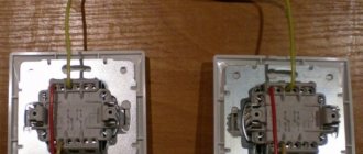
This is what a chain looks like consisting of two single-key and a couple of two-key pass-through switches. This is for example. Such a chain can be used, for example, in long office corridors. In some cases, it is called a walk-through corridor light switch.
In this article we will talk about a scheme according to which you can connect a two-key pass-through type switch as usual to two lighting switching groups.
Why is this necessary? – again, practice. Recently, while carrying out electrical installation work on a request to move sockets and switches in an apartment, at the finish line, when it came to installing switching devices, it turned out that the customer in a hurry bought pass-through two-key switches, instead of the usual ones, without paying attention to the arrows indicated on the keys. The client didn’t want to go change, he just groaned - “Well, maybe somehow, huh?”
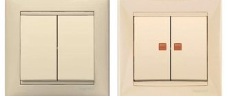
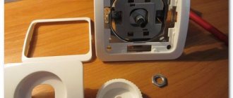
Having marked it with the circuit, I connected the pass-through two-key switch Fig. 1 to normal operation, installing a jumper in the standard circuit between the two contact groups. The directional arrows on the switch keys did not confuse the customer; on the contrary, they seemed appropriate. In general, all parties were satisfied.
Maybe this visual diagram of connecting a pass-through two-key switch to normal mode will be useful to someone.
Any home craftsman can assemble such a simple connection diagram using one jumper with his own hands.
Installing a pass-through switch is optimal when it is necessary to control a lighting device from several different places. Knowing the connection diagram, you can use a traditional device for such a system. To ensure comfortable control of the light source, you need to know how to connect a pass-through switch like a regular one.
Design Features
Based on the number of switched electrical circuits, devices can be one-, two-, or three-key. Terminals with screw or spring terminals. The design also depends on the functional purpose. The types of devices differ when used for external or internal wiring.
Such electrical equipment is designed to turn one or a group of lamps on and off from different places. There is no need to go back to the other end of the room to press a key. Electrical appliances are used in large apartments, in corridors and on stairs, when lighting garden paths, in the bedroom. In addition to convenience, this saves energy.
Walk-through switches are also used in concert halls, stadiums, underground passages and tunnels, and in the entrances of high-rise buildings.
Normally open or closed contactor - which is better?
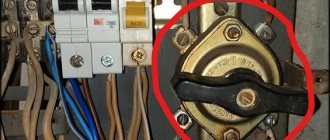
Also look at the design of the device. Contactors are available with normally open (NO) and normally closed (NC) contacts.
Mistake #4
We'll need open ones, not closed ones.
This means that when no voltage is supplied to the starter's closing coil, the power contacts remain open and no current flows through them.
Here is the corresponding drawing and designation of such a series on the device body.
It would seem that a contactor with normally closed contacts is much better, because its coil will not be under 220V voltage all the time.
However, always take into account and take into account not only normal modes, but also emergency ones.
In an emergency (damage, fire and failure of the control coil), your entire switchboard and devices remain energized. But this shouldn’t happen.
When the introductory circuit breaker gets stuck, a serious problem arises with de-energization of the entire house.
Also, the solenoid coil at the NO (normally open) contactor will be energized when you are at home. Whereas with NC equipment when you are not at home. Roughly speaking, the NO contactor will buzz when you are nearby, and the NC contactor will buzz when you are far away.
Think of it as a vacation of almost a month or more. The second option (NC) is less safe and in your absence you simply will not be able to quickly respond to the development of an emergency situation.
Differences between pass-through and traditional switch
The switches are no different in appearance. The internal structure of a conventional one is equipped with one input and output. Can have up to three keys, allowing you to control multiple lighting sources. Most often they are installed near the entrance to the room. The connection is made using two terminals.
A classic checkpoint has two exits and one entrance. In this case, the electric current is not interrupted, but is redirected to any other output. There is a diagram underneath the product body. The single-key pass-through is equipped with three-wire switching and three terminals with copper contacts. This is a switch that redirects the current to other areas.
By design, installation method and type of control, switches can be:
They are also classified depending on voltage and current, degree of protection, and climatic conditions in which they are installed.
It is important not to confuse an electrical appliance with a changeover or crossover device. On the pass key there is a vertical triangle, in the rest it is located in the horizontal direction.
Control circuits
Electromagnetic contactors do not have mechanical locking in the on position. To ensure that the rod is held during operation, a self-retaining circuit is used. This is a fairly convenient technique that allows you to switch the coil power circuit with various protection and automation devices of the electric drive. The exception is assemblies controlled by PLC or relay automation.
The simplest self-retaining circuit includes one additional blocking normally open contact. The coil power circuit is connected through a normally open contact of the start button. The second circuit is connected in parallel; it consists of a series-connected blocking contact and a normally closed contact of the “Stop” button. Thus, when the contactor is turned on, a blocking contact is closed, which is held during operation and supplies power to the coil. If it is necessary to stop, the coil power circuit is opened with the “Stop” button.
Contactor self-retaining circuit: L1, L2, L3 - three-phase power supply phases; N - neutral; KM - magnetic starter coil; NO13-NO14 - additional normally open contact; M - asynchronous motorThere are also more complex control schemes
Thus, the use of a normally closed contact of the start button of one contactor can be used to prevent the simultaneous operation of two starters, which, in particular, may be important when constructing reversing circuits or may be due to other technological needs. The same principle can operate when using a normally closed blocking contact of one contactor, which is connected in series with the start button contact of another.
Scheme of reverse engine starting: KM1, KM2 - coils of magnetic starters; NO KM1, NO KM2 - normally open contacts of starters; NC KM1, NC KM2 - normally closed contacts of starters; KK - thermal relay
The self-retaining circuit can also include limit switches, dry contact sensors and various protective devices. Automatic activation of the contactor is also possible; for these purposes, the button is replaced or duplicated by parallel activation of limit switches or sensors. Thus, the complexity and control schemes of an automated electric drive are practically unlimited.
How to connect a pass-through device
The current is supplied through a distribution box. Select a suitable location, install it and remove the three-core cable. In addition to phase and neutral, it is equipped with a grounding wire, which makes the system safe. Factory color coding of the cores simplifies installation. More often it is a copper flexible cable, the cross-section of individual wires is from 1 to 1.5 mm.
Preliminary markings are made where the switches and lamps will be located. Then the walls are tapped and the conductor lines are laid out. Drill niches for mounting the switch mechanism. After the preparatory work, you can connect the entire system.
For a correct and safe connection, the following sequence must be observed:
- First of all, you need to make sure which wire in the box is the phase, it is usually red.
- Turn off the voltage.
- A phase is supplied to a nearby switch and connected to terminal “1”.
- According to the markings on the terminal block, connect the remaining conductors, remembering the corresponding colors.
- Do the same work on the other switch.
- The core from the second switch with the lamp phase is connected to the bright wire in the junction box.
Installation of distribution box
At the very beginning of the installation work, it is worth starting with the installation of a distribution box, where all the necessary wiring will be located, connecting to each other in a certain order, creating a switch circuit with one key.
The box itself can be recessed into the wall, or maybe along the top, but this in no way affects the installation process itself, it will be exactly the same.
Next, the socket box is mounted - the base for installing the components of the socket or switch. The next step according to the instructions for connecting switches is to install a switch (automatic), which serves to protect the electrical network from sudden overloads, as well as from short circuits in the network. It is often placed in a power panel.
How to turn a simple switch into a pass-through switch
To convert, you will need two switches - one-key and two-key. It is better if they are from the same manufacturer and the same size. The essence of the modification is the addition of one more contact to a two-key ordinary switch. First you need to make sure that the design allows you to swap the terminals.
On the ceramic base there is a group of common, private and rocker contacts. The electrical part is removed, one of the moving contacts is turned 180°. One area from the total group is cut off. The resulting mechanism is assembled and its operation is checked.
The device is closed with a single lid. You can leave double keys by gluing them together. Thus, one circuit is activated in one position. By switching the key, another one will be connected.
Preparing for work
Installing the switch is simple. The amount of preparatory work is much larger because it includes laying wires.
- First determine where the switch will be located . The location is determined by convenience and certain requirements. For example, you cannot place a switch next to the sink in the kitchen; it is prohibited to install the device in bathrooms, except for waterproof ones. The distance from the floor is not regulated. Previously, switches were located high, at a distance of 150–170 cm from the floor. To turn on the lamp, you had to raise your hand. Today, it is more often placed at a height of 110–120 cm. In this case, the light in the room is turned on while holding the hand down.
- The switch is connected to the power cable . The latter must be routed from the junction box to the location of the device. To do this, mark the installation location of the device and the line along which the cable is laid. Usually the wire is inserted into the switch from below.
- A groove is cut out in the wall for the cable . To do this, use wall chasers or a grinder with a disk to cut the boundaries of the groove, and the remainder is removed with a hammer and screwdriver. The power cable can be mounted directly on the wall, but this is not aesthetically pleasing and dangerous: the wire is easily damaged. Cable laying under the floor plinth is allowed.
- Cut a hole for the switch . To do this you will need a drill with a crown attachment.
- from the junction box into the groove . The cable should not be pulled, it should lie freely. It is fixed in the groove with clamps or clamps.
- The groove is sealed with plaster, gypsum, and alabaster. After the material has dried, you can continue working.
- The same is done for the cable powering the lamp. The groove for it is cut from the switch to the installation site of the lighting fixture.
A phase wire runs from the switch to the lamp. Zero is supplied from the distribution box.
Changeover switch
It is equipped with two inputs and outputs, has four terminals, and immediately switches a pair of contacts. Not used as often, but in some cases indispensable. Makes it easier to move around at night:
- in a large corridor or hall with many doors;
- in an apartment with three levels;
- a bedroom with a switch at the entrance and two next to the bed;
- while in the house, it is possible to control the lamps in the garage, on the terrace, in the gazebo.
To equip staircase lighting in a three-story building, it is necessary to create three control points. The cross type rocker switch is not used by itself. It must be connected in the gap between the pass-through switches. Knowing the procedure for connecting a pass-through, it’s easy to figure out how to make a rocker switch.
Their number can be up to 10, but they should always be located between the passageways.
There are several schemes for controlling lighting from 3 or more places. You can assemble the circuit through the distribution panel, or bypassing it. It is possible to connect several types of lamps at once.
Using thermal relays with magnetic starters
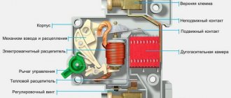
The possibility of triggering the thermal relay (1) is provided in case of an emergency. The circuit contact (4) is broken, followed by disconnection of the coil and return of the core to its original state by special return springs. After disconnecting the contacts in this way, the dangerous voltage is removed in the emergency area.
Connecting a magnetic starter together with a thermal relay provides reliable protection of electrical units from possible overloads. These devices serve as an effective addition to automatic machines, the bimetallic strips of which cannot always protect during an accident. Although, the principle of operation of a thermal relay is the same as that of the thermal element of an automatic protective switch. However, the thermal relay does not automatically switch off, but only sends a set signal to perform this operation. It must be accurately and competently recognized, and put into practice in a timely manner.
A thermal relay equipped with power contacts can be directly connected to a magnetic starter without the use of conductors. However, products from different manufacturers may not match, fit or interact with each other.
Each thermal relay is equipped with two groups of contacts, independent of each other - normally closed and normally open. To break the circuit, a closed contact is used, operating through the STOP button. All working contacts are present in the circuit intended for control. They are connected directly next to the coil, but can be placed in other convenient places.
The actuation process of the thermal relay is completely invisible from the outside. Returning to the original state is carried out using a small button located on the panel. You do not need to transfer the contacts immediately, but only after the relay has cooled down, otherwise they will not be securely fixed. Before the very first use, it is recommended to press the button to avoid careless switching during transportation.
Disadvantages of pass-through devices
The position of the keys does not allow you to determine whether the system is turned off or on. For example, it may not be possible to immediately understand whether the lights are turned off or a light bulb has burned out. It is impossible to control a lighting device from different places at the same time. A large number of connected devices means a lot of twists in the junction box. Connection errors force you to reassemble the entire circuit.
The pass-through switch has many functionalities. But to connect it, you need to purchase another device. The number of connecting wires also increases, which increases the overall cost of the system. An ordinary switch has a relatively low price, but loses in functionality.
://
A pass-through switch is, strictly speaking, not a switch, but a switch . Although people call it a switch, because it is used to turn off the light. In this article I will also adhere to folk traditions.
Using a pass-through switch is very convenient where you need to turn on or off lighting from different places. As its name suggests, such a switch can be installed in aisles.
Other examples of application are large rooms, corridors, stairs, etc.
In order to turn the light on or off, in this case you need to switch one of the switches (usually there are two, but there may be more) to the opposite position.
Switch instead of master button
The most basic load sharing is organized using an additional switch in the electrical panel. No, not like that